EP0229995B1 - Continuous sterilizing and filling apparatus - Google Patents
Continuous sterilizing and filling apparatus Download PDFInfo
- Publication number
- EP0229995B1 EP0229995B1 EP86117431A EP86117431A EP0229995B1 EP 0229995 B1 EP0229995 B1 EP 0229995B1 EP 86117431 A EP86117431 A EP 86117431A EP 86117431 A EP86117431 A EP 86117431A EP 0229995 B1 EP0229995 B1 EP 0229995B1
- Authority
- EP
- European Patent Office
- Prior art keywords
- pressure tank
- materials
- pressure
- filler means
- valve
- Prior art date
- Legal status (The legal status is an assumption and is not a legal conclusion. Google has not performed a legal analysis and makes no representation as to the accuracy of the status listed.)
- Expired
Links
- 230000001954 sterilising effect Effects 0.000 title claims description 17
- 239000000463 material Substances 0.000 claims description 53
- 239000000945 filler Substances 0.000 claims description 37
- 238000011144 upstream manufacturing Methods 0.000 claims description 7
- 239000007788 liquid Substances 0.000 claims description 4
- 230000004044 response Effects 0.000 claims description 4
- 239000007787 solid Substances 0.000 claims description 4
- 238000001514 detection method Methods 0.000 claims 2
- 238000010586 diagram Methods 0.000 description 4
- 238000004659 sterilization and disinfection Methods 0.000 description 4
- 238000009825 accumulation Methods 0.000 description 2
- 230000006872 improvement Effects 0.000 description 2
- 238000000034 method Methods 0.000 description 2
- 230000009471 action Effects 0.000 description 1
- 238000010276 construction Methods 0.000 description 1
- 230000036512 infertility Effects 0.000 description 1
- 238000004519 manufacturing process Methods 0.000 description 1
- 230000004048 modification Effects 0.000 description 1
- 238000012986 modification Methods 0.000 description 1
- 239000002245 particle Substances 0.000 description 1
Images

Classifications
-
- A—HUMAN NECESSITIES
- A23—FOODS OR FOODSTUFFS; TREATMENT THEREOF, NOT COVERED BY OTHER CLASSES
- A23B—PRESERVATION OF FOODS, FOODSTUFFS OR NON-ALCOHOLIC BEVERAGES; CHEMICAL RIPENING OF FRUIT OR VEGETABLES
- A23B2/00—Preservation of foods or foodstuffs, in general
- A23B2/40—Preservation of foods or foodstuffs, in general by heating loose unpacked materials
- A23B2/42—Preservation of foods or foodstuffs, in general by heating loose unpacked materials while they are progressively transported through the apparatus
-
- B—PERFORMING OPERATIONS; TRANSPORTING
- B65—CONVEYING; PACKING; STORING; HANDLING THIN OR FILAMENTARY MATERIAL
- B65B—MACHINES, APPARATUS OR DEVICES FOR, OR METHODS OF, PACKAGING ARTICLES OR MATERIALS; UNPACKING
- B65B3/00—Packaging plastic material, semiliquids, liquids or mixed solids and liquids, in individual containers or receptacles, e.g. bags, sacks, boxes, cartons, cans, or jars
- B65B3/04—Methods of, or means for, filling the material into the containers or receptacles
- B65B3/10—Methods of, or means for, filling the material into the containers or receptacles by application of pressure to material
- B65B3/14—Methods of, or means for, filling the material into the containers or receptacles by application of pressure to material pneumatically
-
- B—PERFORMING OPERATIONS; TRANSPORTING
- B65—CONVEYING; PACKING; STORING; HANDLING THIN OR FILAMENTARY MATERIAL
- B65B—MACHINES, APPARATUS OR DEVICES FOR, OR METHODS OF, PACKAGING ARTICLES OR MATERIALS; UNPACKING
- B65B55/00—Preserving, protecting or purifying packages or package contents in association with packaging
- B65B55/02—Sterilising, e.g. of complete packages
- B65B55/12—Sterilising contents prior to, or during, packaging
- B65B55/14—Sterilising contents prior to, or during, packaging by heat
Definitions
- the present invention relates to an improvement in a sterilizing apparatus for sterilizing materials to be filled, while applying a back pressure to a sterilizer by a back pressure tank having a controllable internal pressure as is disclosed in US-A-4 597 945 and GB-A-2 137 865 which will be referred to as the "prior art".
- the improvement resides in the capability of continuously filling a container with the materials which have been sterilized under aseptic condition like in the prior art.
- the materials to be filled are herein termed a liquid or pastes containing solid particles.
- the materials are sterilized by the sterilizer under a back pressure or the internal pressure of the back pressure tank, and the materials thus sterilized are sequentially recovered by the back-pressure tank.
- the passage between the sterilizer and the back-pressure tank is once shut off by a valve, and the sterilized materials are delivered for batch-filling to a vacant filler means.
- US-A-4 450 981 discloses a precision material filling system utilizing pneumatic pressure maintained within closely held tolerance limits to impose a constant dispensing force upon the material being dispensed.
- the filling system according to US-A-4 450 981 comprises a storage tank which feeds a buffer tank through a solenoid activated valve and a check valve.
- the storage tank comprises a lower product level sensing switch and an upper product level sensing switch.
- the buffer tank comprises lower and upper level sensing switches. The actuation of the solenoid valve is controlled by the level sensing switches.
- the present invention contemplates to solve the above-specified problem of the prior art and has an object to provide an apparatus of continuously and simultaneously sterilizing and filling materials.
- the gist of the present invention resides in the combination of control means and a filler means with the sterilizing apparatus of the prior art having the sterilizer and the back-pressure tank.
- the filler means is disposed downstream of the back-pressure tank, and the control means is interposed between the back-pressure tank and the filler means for controlling the flow rate of the materials, which is delivered from the former to the latter, to a value equal to or lower than the flow rate of the materials which are delivered from the steriliser to the back-pressure tank.
- the control means avoids a remarkable pressure loss which might otherwise occur in the series passages of the apparatus. Moreover, the outflow of air from the back pressure tank to the filler means is minimized so that the back pressure can be applied to the sterilizer as stably as possible. At the same time, the sterilized material is continuously fed to the filler means so that it can be filled with its upstream sterilization.
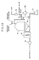
- a control means 13 which includes a (sterile) valve 131.
- This valve 131 may be exemplified by a diaphragm valve or a ball valve, which has a function to allow the solids to pass therethrough in addition to the flow control function.
- the filler means 12 includes a filling piston 121, a filling nozzle 122, and a filling reservoir 123 disposed upstream of the filler means proper 121 and 122.
- This reservoir 123 is equipped with a level sensor 132 which forms part of the control means 13.
- This control means 13 further includes a control unit 133 which is connected between the level sensor 132 and the aforementioned valve 131.
- the materials in the form of liquid are fed by a feeding device means 14 and through a sterilizer 16 to the back-pressure tank 11 which is vented to the atmosphere through a pressure relief valve V1 and connected to a compressed air tank (not-shown) through a pressure relief valve V2 and a sterilizing filter 15.
- the materials are sterilized by the sterilizer 16 under the back pressure controlled by the back pressure tank 11.
- the materials thus sterilized are delivered through the back-pressure tank 11 toward the filler means 12.
- the delivered materials are once reserved in the filler means reservoir 123 and are then filled in a container such as a bag 17 by the coaction of the filling piston 121 and the filling nozzle 122.
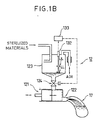
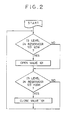
- the apparatus 10 of the present invention continues its sterilizing and filling operations in the manners described above. If, during this run, the filling rate (or capacity) of the filling piston 121 and the filling nozzle 122 fails to match the flow rate of the materials fed to them, this materials will gradually accumulate in the filling reservoir 123. Then, in order to prevent an excessive accumulation, the control means 13 causes its valve 131 and level sensor 132 to act under an electrical control, as will be described in the following with additional reference to the flow chart of Fig. 2.
- the level sensor 132 detects this lower limit LL and control unit 133 produces an "OFF" signal to hold the valve 131 open.
- the materials accumulate in the filling reservoir 123 so that the level reaches a predetermined upper limit UL, as indicated in Fig. 1B, the level sensor 132 detects this upper limit UL and the control unit 133 produces an "ON" signal to close the valve 131.
- control of the control means 13 is accomplished such that the flow rate of the materials delivered from the back-pressure tank 11 to the filler means 12 is made slightly lower than the flow rate of the materials fed from the sterilizer 16 to the back pressure tank 11.
- the apparatus 10 runs, as described above, its pressure neither loses, nor is any outflow of air from the back-pressure tank 11 to the filler means 12.
- the internal pressure of the back pressure tank 11 is controlled to a remarkably stable level so that the sterilizer 16 can operate under a sufficiently stable back pressure.
- the sterilized materials are continuously fed from the filling reservoir 123 to the filling piston 121 and nozzle 122 so that its filling operation can be successively conducted.
- the materials may gradually accumulate in the back-pressure tank 11. Despite of this gradual accumulation, however, the run of the apparatus 10 can be continued for a predetermined period if the capacity of the back pressure tank 11 is determined at an appropriate value.
- the flow rate of the sterilized materials can be controlled to a desired value by the ON/OFF control of the valve 131, which is affected by the control unit 133 connected between the valve 131 and the level sensor 132.
- This control is effective especially in case the materials contain solids, because the ON/OFF control does not establish any narrow gap at the valve 131.
- a valve 124 may be interposed between the filler means reservoir 123 and the filler means proper 121 and 122. That valve 124 can also be controlled by the control unit 133 which responds to a (not-shown) sensor for detecting operating difficulties, if any, of the filler means proper 121 and 122. If the sensor detects such operating difficulties, the control unit 133 produces a signal to close the valve 124 so that the materials can be temporarily reserved in the reservoir 123 to allow its sterilization to continue.
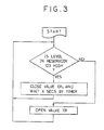
- control means 13 may further include a (not-shown) sensor for detecting the level of the materials in the back-pressure tank 11 to produce a signal when the materials level drops to a predetermined low level. In response to this signal, the control unit 133 can close the valve 131.
- the control unit 133 When the materials to be filled accumulate in the filling reservoir 123 to arrive at the predetermined upper level UL, this arrival is detected by the level sensor 132. In response to this, the control unit 133 produces the signal to close the valve 131. It should be noted here that the control unit 133 may have a (not-shown) timer for continuing the signal production for X seconds. As a result, the closure of the valve 131 is continued for X seconds. Thus, the flow rate of the materials fed to the filling reservoir 123, i.e., the materials to be delivered from the back-pressure tank 11 to the filler means 12 are controlled.
- the period of X seconds, for which the closure of the valve 131 is continued by the timer is so determined as to satisfy the matching condition between the flow rate of the materials to be delivered from the back-pressure tank 11 to the filler means 12 and the filling capacity of the filler means proper 121 and 122.
- valve 131 of Fig. 1A is replaced by a feeding device such as a rotary feeding device 134 which will not deteriorate the sterility of the apparatus 10'.
- a feeding device such as a rotary feeding device 134 which will not deteriorate the sterility of the apparatus 10'.
- the construction and operation of this modified apparatus 10' are similar to those of the apparatus 10 of Figs. 1A and 1B except the action of the rotary feeding device 134 and will therefore be omitted here.
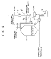
- the flow rate of the sterilized materials to be fed from the back-pressure tank 11 to the filler means 12 can be controlled by another method, as will be described in the following with reference to Fig. 5.
- the pipe leading to the back-pressure tank 11 for supplying sterilized air is denoted as 181
- the upstream pipe leading from the sterilizer (although not shown) to the back pressure tank 11 for feeding the sterilized materials is denoted as 182
- the downstream pipe leading from the back pressure tank 11 to the filler means 12 for feeding the materials to be packed is denoted as 183.
- the air supply pipe 181 is vented to a compressed air tank (not-shown) through the control valve 137 and the sterilizing filter 15, as has been described with reference to Fig. 1A.
- the control means 13 in this embodiment includes a pressure sensor 135 which is attached to the back-pressure tank 11 for detecting the internal pressure of the same. Further included is a control unit 136 through which the pressure sensor 135 is connected to a control valve 137 disposed in the air supply pipe 181. This control valve 137 controls the flow rate of the sterilized air to be supplied through the pipe 181 to the back-pressure tank 11.
- the internal pressure in the tank 11 can be controlled to such an appropriate level as can apply a sufficient back pressure to the sterilizer (although not shown) while compensating the pressure to be lost in the downstream pipe 183.
- the air supply pipe 181, the upstream pipe 182 and the downstream pipe 183 are set to have the above-specified diameter relationships, i.e., D1 > D3 and D2 ⁇ D3, the outflow rate of the air to the downstream pipe 183 will not exceed the supply rate of the air to the back-pressure tank 11. This will avoid the pressure loss in the apparatus 10 ⁇ .
- the flow rate of the materials delivered from the back pressure tank 11 to the filler means 12 is controlled to a value equal to the flow rate of the materials fed from the (not-shown) sterilizer to the back pressure tank 11 so that the sterilized materials to be filled can be continuously fed to and filled by the filler means 12.
- the control of the internal pressure of the back-pressure tank 11 is accomplished by the coactions of the pressure sensor 135, the control unit 136 and the control valve 137. Specifically, when the internal pressure detected by the pressure sensor 135 is low, the control unit 136 responds to the sensor 135 to produce a signal to open the control valve 137. With this valve 137 being opened, the sterilized air is introduced through the open valve 137 into the back-pressure tank 11 via the air supply pipe 181 so that the internal pressure of the back pressure tank 11 may be restored to a predetermined level.
Landscapes
- Engineering & Computer Science (AREA)
- Life Sciences & Earth Sciences (AREA)
- Mechanical Engineering (AREA)
- Wood Science & Technology (AREA)
- Zoology (AREA)
- Chemical & Material Sciences (AREA)
- Food Science & Technology (AREA)
- Polymers & Plastics (AREA)
- Food Preservation Except Freezing, Refrigeration, And Drying (AREA)
- Basic Packing Technique (AREA)
- Apparatus For Disinfection Or Sterilisation (AREA)
Applications Claiming Priority (2)
| Application Number | Priority Date | Filing Date | Title |
|---|---|---|---|
| JP60282350A JPS62146128A (ja) | 1985-12-16 | 1985-12-16 | 殺菌充填装置 |
| JP282350/85 | 1985-12-16 |
Publications (2)
| Publication Number | Publication Date |
|---|---|
| EP0229995A1 EP0229995A1 (en) | 1987-07-29 |
| EP0229995B1 true EP0229995B1 (en) | 1991-08-21 |
Family
ID=17651270
Family Applications (1)
| Application Number | Title | Priority Date | Filing Date |
|---|---|---|---|
| EP86117431A Expired EP0229995B1 (en) | 1985-12-16 | 1986-12-15 | Continuous sterilizing and filling apparatus |
Country Status (4)
| Country | Link |
|---|---|
| US (1) | US4861559A (enExample) |
| EP (1) | EP0229995B1 (enExample) |
| JP (1) | JPS62146128A (enExample) |
| DE (1) | DE3681009D1 (enExample) |
Families Citing this family (18)
| Publication number | Priority date | Publication date | Assignee | Title |
|---|---|---|---|---|
| US4961446A (en) * | 1987-08-05 | 1990-10-09 | Promation Incorporated | Container filling system |
| DE3885672T2 (de) * | 1987-08-05 | 1994-03-10 | Promation Inc | Behälterfüllsystem. |
| IL91842A0 (en) * | 1988-10-03 | 1990-06-10 | Deepfreezing & Preserving Prop | Installation and method for the pasteurization and aseptic packaging of food pieces |
| US6419850B1 (en) | 1991-06-03 | 2002-07-16 | Airel-West | System and composition for decontaminating fluids |
| US5285828A (en) * | 1992-05-28 | 1994-02-15 | Promation Incorporated | Apparatus for introducing filler material into containers |
| JP2844043B2 (ja) * | 1993-08-30 | 1999-01-06 | ハウス食品株式会社 | 食品殺菌装置 |
| US5503064A (en) * | 1994-08-31 | 1996-04-02 | Custom Control Products, Inc. | Apparatus and method for controlling a pasteurizing system |
| JP3308477B2 (ja) * | 1997-12-01 | 2002-07-29 | ハウス食品株式会社 | 無菌液体調理ソースの製造方法及び装置 |
| US9085449B2 (en) * | 2010-03-08 | 2015-07-21 | The Coca-Cola Company | Aseptic dosing system |
| US10252852B2 (en) | 2011-04-22 | 2019-04-09 | Jbt Food & Dairy Systems B.V. | Adaptive packaging for food processing systems |
| US9241510B2 (en) | 2011-04-23 | 2016-01-26 | Ics Solutions B.V. | Apparatus and method for optimizing and controlling food processing system performance |
| US8893518B2 (en) | 2011-04-25 | 2014-11-25 | Ics Solutions B.V. | Accelerating, optimizing and controlling product cooling in food processing systems |
| US9955711B2 (en) | 2011-05-20 | 2018-05-01 | Jbt Food & Dairy Systems B.V. | Method and apparatus for increased product throughput capacity, improved quality and enhanced treatment and product packaging flexibility in a continuous sterilizing system |
| US9131729B2 (en) | 2011-09-28 | 2015-09-15 | Ics Solutions B.V. | Safe and efficient thermal transfer media for processing of food and drink products |
| NZ705064A (en) * | 2012-09-24 | 2016-06-24 | Nestec Sa | Methods and systems for coordination of aseptic sterilization and aseptic package filling rate |
| WO2016209255A1 (en) * | 2015-06-26 | 2016-12-29 | Transitions Optical, Inc. | Filling system for spin coater coating cartridges |
| JP7344638B2 (ja) * | 2018-11-06 | 2023-09-14 | 大成ラミック株式会社 | 液状被包装物の吐出制御装置および液状被包装物の吐出制御方法 |
| WO2024115087A1 (en) * | 2022-11-30 | 2024-06-06 | Tetra Laval Holdings & Finance S.A. | Device for creating a backpressure in a fluid line |
Family Cites Families (5)
| Publication number | Priority date | Publication date | Assignee | Title |
|---|---|---|---|---|
| US2019491A (en) * | 1927-08-06 | 1935-11-05 | Grindrod Process Corp | Apparatus for treating foods |
| WO1980001797A1 (en) * | 1979-02-22 | 1980-09-04 | D Haig | Precision material filling systems |
| JPS59164062A (ja) * | 1983-03-09 | 1984-09-17 | ハウス食品工業株式会社 | 殺菌装置 |
| GB2137865B (en) * | 1983-03-09 | 1987-02-18 | House Food Industrial Co | Sterilization apparatus |
| GB2139994B (en) * | 1983-04-19 | 1986-08-13 | House Food Industrial Co | Sterilizing + filling apparatus |
-
1985
- 1985-12-16 JP JP60282350A patent/JPS62146128A/ja active Granted
-
1986
- 1986-12-15 DE DE8686117431T patent/DE3681009D1/de not_active Expired - Lifetime
- 1986-12-15 EP EP86117431A patent/EP0229995B1/en not_active Expired
- 1986-12-16 US US06/942,376 patent/US4861559A/en not_active Expired - Lifetime
Also Published As
| Publication number | Publication date |
|---|---|
| EP0229995A1 (en) | 1987-07-29 |
| US4861559A (en) | 1989-08-29 |
| DE3681009D1 (de) | 1991-09-26 |
| JPH0351186B2 (enExample) | 1991-08-06 |
| JPS62146128A (ja) | 1987-06-30 |
Similar Documents
| Publication | Publication Date | Title |
|---|---|---|
| EP0229995B1 (en) | Continuous sterilizing and filling apparatus | |
| JP4711369B2 (ja) | 基材上に材料を分配する方法および装置 | |
| KR100692995B1 (ko) | 유체의 저장 및 분배를 위한 장치 및 방법과 사용 유체의공급 방법 | |
| US4450981A (en) | Precision material filling systems | |
| YU56400A (sh) | Uređaj za istakanje tečnosti pod pritiskom | |
| FI87441B (fi) | Foerfarande och anordning foer aseptisk fyllning av en foerpackning med vaetska. | |
| AU1917797A (en) | Patient controllable drug delivery system flow regulating means | |
| CA2146146A1 (en) | Accumulator-based liquid metering system and method | |
| AU2672984A (en) | Apparatus to fill containers to a predetermined level | |
| US4860804A (en) | Filled amount control system | |
| CA2366733A1 (en) | Method and device for filling a pressure tank with a fluid | |
| AU6209994A (en) | Device for supplying low fluid flow rates from a container | |
| AU684493B2 (en) | Dispensing method and apparatus | |
| NZ501243A (en) | An apparatus for filling a container with gas at a preselected pressure | |
| GB2300674B (en) | An improved valve for a device for packaging and dispensing a substance stored under pressure, a device fitted therewith,and a method of manufacture | |
| TW238291B (enExample) | ||
| WO1998027288A3 (en) | Dispenser and method and valve | |
| EP0900345B1 (en) | A fill system control apparatus | |
| AU3520089A (en) | Method and apparatus for minimizing foam in filling cartons | |
| JP3987152B2 (ja) | コンテナーからの粉体放出量の制御方法及び装置 | |
| CA2039288A1 (en) | Main valve and seat for use in filling containers to a predetermined level | |
| AU2137295A (en) | Process and device for controlling the filling process when filling packaging containers | |
| EP0971165A3 (en) | Pumpless liquid dispensing system | |
| JP2653492B2 (ja) | 高分子熱可塑性物質の液化のための装置 | |
| JP2578608Y2 (ja) | 自動包装機の袋把持位置検知装置 |
Legal Events
| Date | Code | Title | Description |
|---|---|---|---|
| PUAI | Public reference made under article 153(3) epc to a published international application that has entered the european phase |
Free format text: ORIGINAL CODE: 0009012 |
|
| AK | Designated contracting states |
Kind code of ref document: A1 Designated state(s): DE FR GB NL SE |
|
| 17P | Request for examination filed |
Effective date: 19870903 |
|
| 17Q | First examination report despatched |
Effective date: 19880725 |
|
| GRAA | (expected) grant |
Free format text: ORIGINAL CODE: 0009210 |
|
| AK | Designated contracting states |
Kind code of ref document: B1 Designated state(s): DE FR GB NL SE |
|
| REF | Corresponds to: |
Ref document number: 3681009 Country of ref document: DE Date of ref document: 19910926 |
|
| ET | Fr: translation filed | ||
| PLBE | No opposition filed within time limit |
Free format text: ORIGINAL CODE: 0009261 |
|
| STAA | Information on the status of an ep patent application or granted ep patent |
Free format text: STATUS: NO OPPOSITION FILED WITHIN TIME LIMIT |
|
| 26N | No opposition filed | ||
| EAL | Se: european patent in force in sweden |
Ref document number: 86117431.6 |
|
| REG | Reference to a national code |
Ref country code: GB Ref legal event code: IF02 |
|
| PGFP | Annual fee paid to national office [announced via postgrant information from national office to epo] |
Ref country code: SE Payment date: 20031204 Year of fee payment: 18 |
|
| PGFP | Annual fee paid to national office [announced via postgrant information from national office to epo] |
Ref country code: GB Payment date: 20031209 Year of fee payment: 18 |
|
| PGFP | Annual fee paid to national office [announced via postgrant information from national office to epo] |
Ref country code: NL Payment date: 20031215 Year of fee payment: 18 |
|
| PGFP | Annual fee paid to national office [announced via postgrant information from national office to epo] |
Ref country code: FR Payment date: 20031226 Year of fee payment: 18 |
|
| PGFP | Annual fee paid to national office [announced via postgrant information from national office to epo] |
Ref country code: DE Payment date: 20031231 Year of fee payment: 18 |
|
| PG25 | Lapsed in a contracting state [announced via postgrant information from national office to epo] |
Ref country code: GB Free format text: LAPSE BECAUSE OF NON-PAYMENT OF DUE FEES Effective date: 20041215 |
|
| PG25 | Lapsed in a contracting state [announced via postgrant information from national office to epo] |
Ref country code: SE Free format text: LAPSE BECAUSE OF NON-PAYMENT OF DUE FEES Effective date: 20041216 |
|
| PG25 | Lapsed in a contracting state [announced via postgrant information from national office to epo] |
Ref country code: NL Free format text: LAPSE BECAUSE OF NON-PAYMENT OF DUE FEES Effective date: 20050701 Ref country code: DE Free format text: LAPSE BECAUSE OF NON-PAYMENT OF DUE FEES Effective date: 20050701 |
|
| EUG | Se: european patent has lapsed | ||
| GBPC | Gb: european patent ceased through non-payment of renewal fee |
Effective date: 20041215 |
|
| PG25 | Lapsed in a contracting state [announced via postgrant information from national office to epo] |
Ref country code: FR Free format text: LAPSE BECAUSE OF NON-PAYMENT OF DUE FEES Effective date: 20050831 |
|
| NLV4 | Nl: lapsed or anulled due to non-payment of the annual fee |
Effective date: 20050701 |
|
| REG | Reference to a national code |
Ref country code: FR Ref legal event code: ST |