EP0229704A2 - Führungseinheit für einen Sondenfinger - Google Patents
Führungseinheit für einen Sondenfinger Download PDFInfo
- Publication number
- EP0229704A2 EP0229704A2 EP87300209A EP87300209A EP0229704A2 EP 0229704 A2 EP0229704 A2 EP 0229704A2 EP 87300209 A EP87300209 A EP 87300209A EP 87300209 A EP87300209 A EP 87300209A EP 0229704 A2 EP0229704 A2 EP 0229704A2
- Authority
- EP
- European Patent Office
- Prior art keywords
- thimble
- core plate
- guide assembly
- passage
- assembly according
- Prior art date
- Legal status (The legal status is an assumption and is not a legal conclusion. Google has not performed a legal analysis and makes no representation as to the accuracy of the status listed.)
- Granted
Links
Images


Classifications
-
- G—PHYSICS
- G21—NUCLEAR PHYSICS; NUCLEAR ENGINEERING
- G21C—NUCLEAR REACTORS
- G21C3/00—Reactor fuel elements and their assemblies; Selection of substances for use as reactor fuel elements
- G21C3/30—Assemblies of a number of fuel elements in the form of a rigid unit
-
- G—PHYSICS
- G21—NUCLEAR PHYSICS; NUCLEAR ENGINEERING
- G21C—NUCLEAR REACTORS
- G21C17/00—Monitoring; Testing ; Maintaining
- G21C17/10—Structural combination of fuel element, control rod, reactor core, or moderator structure with sensitive instruments, e.g. for measuring radioactivity, strain
- G21C17/108—Measuring reactor flux
-
- Y—GENERAL TAGGING OF NEW TECHNOLOGICAL DEVELOPMENTS; GENERAL TAGGING OF CROSS-SECTIONAL TECHNOLOGIES SPANNING OVER SEVERAL SECTIONS OF THE IPC; TECHNICAL SUBJECTS COVERED BY FORMER USPC CROSS-REFERENCE ART COLLECTIONS [XRACs] AND DIGESTS
- Y02—TECHNOLOGIES OR APPLICATIONS FOR MITIGATION OR ADAPTATION AGAINST CLIMATE CHANGE
- Y02E—REDUCTION OF GREENHOUSE GAS [GHG] EMISSIONS, RELATED TO ENERGY GENERATION, TRANSMISSION OR DISTRIBUTION
- Y02E30/00—Energy generation of nuclear origin
- Y02E30/30—Nuclear fission reactors
Definitions
- the present invention relates to a guide for directing a thimble into a fuel assembly in a nuclear power plant, and more particularly, to a thimble guide the length of which can be readily changed.
- a typical pressurized water reactor includes a reactor vessel which contains nuclear fuel, a coolant (water) which is heated by the nuclear fuel, and means for monitoring and controlling the nuclear reaction.
- the reactor vessel is cylindrical, and is provided with a hemispherical bottom and a hemispherical top which is removable.
- Hot water is conveyed from and returned to the vessel by a reactor coolant system which includes one or more reactor coolant loops (usually three or four loops, depending upon the power-generating capacity of the reactor).
- Each loop includes a pipeline to convey hot water from the reactor vessel to a steam generator, a pipeline to convey the water from the steam generator back to the reactor vessel, and a pump.
- the steam generator is essentially a heat exchanger which transfers heat from the reactor coolant system to water from a source that is isolated from the reactor coolant system; the resulting steam is conveyed to a turbine to generate electricity.
- the water within the vessel and the coolant system is maintained at a high pressure to keep it from boiling as it is heated by the nuclear fuel.
- Nuclear fuel is supplied to the reactor incorporated in fuel assemblies.
- Each fuel assembly includes a base element called a bottom nozzle and a bundle of fuel rods and tubular guides which are supported on the bottom nozzle.
- the fuel rods have cylindrical housings which are filled with pellets of fissionable material enriched with U-235.
- the tubular guides accommodate measuring instruments and movably mounted control rods of neutron-absorbing material.
- a typical fuel assembly for a pressurized water reactor is about 4.1 meters long, about 19.7 centimeters wide, and has a mass of about 585 kg, and a typical four loop reactor might contain 196 such fuel assemblies supported parallel to one another on a core plate within the reactor vessel.
- Measuring instruments are employed to promote safety and to permit proper control of the nuclear reaction.
- a neutron flux map is generated periodically, such as every 28 days, using data gathered by neutron flux detectors which are moved through a number of randomly selected fuel assemblies.
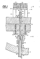
- closed stainless steel tubes known as flux thimbles extend through the bottom of the reactor vessel and into the fuel assemblies which have been selected as measuring sites. This will now be explained in more detail with reference to Figure 1 illustrating a conventional flux-thimble guide arrangement.
- a core plate 10 about 44.5 cm thick is horizontally mounted within a reactor vessel, a wall portion of which, located at the hemispherical bottom end cap of the vessel, is shown at 12.
- the plate 10 supports a plurality of fuel assemblies, a lower portion of one of which is shown at 14 so including a bottom nozzle 16 having four legs 18 which are joined to a platform 20 having a central aperture 22 therein.
- Supported on the platform 20 are fuel rods 23 and an instrumentation tube 24 which is aligned with the aperture 22 and extends to the top nozzle (not illustrated) of the fuel assembly 14.
- a passage 26 having a threaded region 28 extends through the core plate 10 in axial alignment with the aperture 22.
- a thimble guide 30 is provided which has a threaded portion and a recessed wrench-receiving region 32 which permits technicians to screw the guide 30 into the threaded region 28 of the passage 26 during the assembly of the reactor. After the guide 30 is threadedly attached in this manner, welds 34 are added for additional security.
- the guide 30 may project 8.58 cm above the upper surface of the plate 10, and there is a gap of 3.48 cm between the upper lip 35 of the guide and the aperture 22 in the bottom nozzle 16.
- a passage 36 extends through the wall 12 of the reactor vessel in axial alignment with the passage 26.
- a vessel-penetration sleeve 38 having an outer diameter of about 3.81 cm extends through passage 36 and is welded at 40 to the vessel wall 12 to provide a seal which is resistant to high pressure.
- a bottom-mounted instrumentation column 42 mounted on the plate 10 extending between the passage 26 and the sleeve 38, comprises a fitting 44 which is secured to the plate 10 by bolts 46, an upper pipe element 48 which is joined to the fitting 44 by welds 50, and a lower pipe element 52 which is joined coaxially to the pipe element 48 at a tie plate (not illustrated).
- the lower pipe element 52 has an inner diameter of 5.08 cm so that there is a gap between it and the sleeve 38.
- a vessel-penetration sleeve such as sleeve 38
- sleeves 38 would be installed in the reactor vessel wall 12 and guides 30 and bottom mounted instrumentation columns 42 would be installed on core plate 10, the columns 42 being secured to one another by tie plates (not illustrated). Then the core plate 10 and attached structures would be lowered into the vessel, with the sleeves 38 fitting into elements 52. In the resulting structure, the upper ends (not illustrated) of sleeves 38 are spaced apart from the lower ends (not illustrated) of upper pipe elements 48, so that sleeves 38 are not in fluid-tight communication with bottom mounted instrumentation columns 42.
- the bore 54 of upper pipe element 48 typically has a diameter of 1.189 cm and terminates in a flared region 56.
- the bore 58 of fitting 44 is typically 1.73 cm in diameter and has flared regions at either end.
- the bore 26 typically has a diameter of 1.91 cm. It should be noted that the channel provided by bores 54, 58, and 26 becomes progressively wider from upper pipe element 48, to fitting 44, to bore 26. This construction facilitates manufacture of the reactor and provides guidance for thimble 60 while avoiding the possibility that it might become stuck in the channel.
- Thimble 60 is a long stainless steel tube which begins at a plate (known as a seal table, not illustrated) outside the reactor vessel and which has a closed end (not illustrated) that is normally disposed inside a fuel assembly.
- Thimble 60 slidably extends through tube 24, guide 30, bore26, bottom-mounted instrumentation column 42, and sleeve 38.
- a stainless steel guide tube (not illustrated) is welded to the outer end of sleeve 36, and thimble 60 extends within the guide tube to the seal table which is typically located in a shielded position near the top of the reactor vessel.
- the guide tube provides a pressure boundary which extends around thimble 60 from wall 12 to the seal table, where a high pressure seal (not illustrated) is provided between the inner wall of the guide tube (not illustrated) and the outer wall of thimble 60.
- thimble 60 provides a low-pressure access channel into the reactor from a shielded position outside of the reactor.
- a flux detector (not illustrated), about 5 cm long, is slidably accommodated within thimble 60 and is attached to a flexible push-pull cable (not illustrated) which extends through thimble 60 to flux-mapping equipment (not illustrated) located beyond the seal table. At periodic intervals, typically once every 28 days, the flux detectors are pushed to the tops of thimbles 60 and are then slowly withdrawn through the fuel assemblies 14 as flux measurements are taken at different heights to provide a neutron flux map of the interior of the reactor.
- the thimbles 60 remain inserted in the instrumentation tubes 24 of the randomly selected fuel assemblies 14 between the periodic flux mapping operations. Thimbles 60 must be withdrawn from fuel assemblies 14, however, at intervals of 12-18 months when the reactor is shut down for refueling and fuel shuttling. During the refueling operation, the nuclear reaction is terminated, the pressure within the reactor vessel is relieved, and the guide tubes (not illustrated) are unsealed from the thimbles 60 at the seal table (not illustrated). The thimbles 60 (which are somewhat flexible) are then withdrawn a distance of about 4.27 meters to free them from the spent fuel assemblies 14, which are thereupon removed via remote control and replaced with fresh fuel assemblies 14. Thimbles 60 are then driven into the fresh fuel assemblies 14, the reactor vessel and seal table are sealed, and power generation begins anew.
- a thimble guide assembly for receiving an elongate thimble which is inserted into a nuclear fuel assembly through a passage in a reactor core plate supporting the fuel assembly, through a space between the core plate and a bottom nozzle of the fuel assembly, and through an aperture formed in the bottom nozzle in axial alignment with the passage in the core plate, characterized by (A) an elongate first element which has a thimble channel axially extending therethrough and includes connecting means for fixedly mounting the first element on said core plate such that the first element projects from the core plate into said space and has its thimble channel axially aligned with the passage in the core plate; and (B) a second element which has a thimble channel extending therethrough and includes connecting means for removably connecting the second element to said first element such that it forms an axial extension thereof and has its thimble channel axially align
- the thimble guide assembly 62 embodying the invention comprises a first or lower element 64 and a second or upper element 98.
- the first or lower element 64 of the assembly 62 includes a projecting portion 66 which extends from the upper surface of the core plate 10, a right-hand threaded portion 68 enabling the element 64 to be screwed into the threaded region 28 of bore 26, and a lower sleeve portion 70 which extends from the threaded portion 68 to the flared region 56 of the upper pipe element 48.
- Sleeve portion 70 is provided with an upper annular shoulder 72 which frictionally engages the bore 26 near its upper end, and a lower annular shoulder 74 which frictionally engages bore 26 adjacent its lower end, the region 76 between the shoulders 72 and 74 being spaced from the wall of the bore 26.
- Sleeve portion 70 provides a uniformly dimensioned flow path 78 between the upper pipe element 48 and the projecting portion 66 even if the bores 54, 58, and 26 have different diametrical dimensions, as in Fig. 1.
- the uniformity of the flow path 78 reduces flow-induced vibration, thus wear of the thimble, such as thimble 60 (Fig. 1), extending therethrough.
- Region 76 is spaced from the wall of the bore 26 in order to reduce the force necessary to insert the lower element 64 during installation thereof.
- the projecting portion 66 is provided with lower and upper annular recesses 80 and 82, a recessed wrench-engaging region 84, and a left-hand threaded sleeve 86.
- An axial passage 87 through the projecting portion 66 is an extension of the flow path 78 through the sleeve portion 70.
- a lower spring clip 88 (also see Figure 3) has a flange portion 90 which is spot-welded at 92 to the core plate 10, and has a sleeve portion 94 with an annular inward protrusion 96 which snaps into the recess 80 of the projecting portion 66.
- the second or upper element 98 of the thimble guide assembly 62 has a threaded region 100 which screws onto the threaded sleeve 86 of the lower element 64.
- Upper spring clip 102 (see also Figure 6) is spot-welded at 104 to element 98, and is provided with an annular inward protrusion 106 which snaps into the annular recess 82 of the lower element 64.
- the element 98 terminates in sloping shoulders 110 and a flat annular lip 112.
- the plane of lip 112 is perpendicular to the longitudinal axis of the cylindrical thimble channel 113 extending through the assembly 62.
- the squared-off configuration at the top of the upper element 98 in contrast to the sloping recess at the upper lip 35 of the thimble guide 30 shown in Figure 1, minimizes the turbulence created by fluid discharge.
- the upper element 98 of the thimble guide assembly 62 having the desired length is screwed onto the lower element 64 and is tightened thereon by means of wrenches applied to regions 84 and 108.
- Spring clips 88 and 102 are then forced onto the elements 64 and 98 until their annular protrusions 96 and 106 snap into place, whereupon welds are formed at 104 to complete the assembly 62.
- the lower sleeve portion 70 is forced into a bore 26 of the core plate 10 until the threaded portion 68 engages the threaded portion 28, whereupon the assembly 62 is tightened by means of a wrench applied to region 84 and welds 92 then are formed.
- the space between the upper tip, i.e., lip 112, of the guide assembly 62 and the aperture 22 is considerably less than the space between the upper tip, i.e. lip 35, of the thimble guide 30 and the aperture 22 in Fig. 1, so that the assembly 62 is more effective in shielding the thimble 60 from turbulence.
- the distance between the lip 112 and the aperture 22 preferably is less than about 2.54 cm and may be as small as 0.64 cm. Since the thimble guide assembly 62 is made of the two elements 64 and 98 screwed together, it can be readily adapted for use with different fuel assembly designs simply by selecting an upper element 98 of the appropriate length.
- the upper element 98 can be exchanged subsequently, if necessary, to compensate for a change in the length of the legs 18 resulting from substitution of a new fuel assembly during refueling. Such exchange is accomplished, after the removal of the spent fuel assembly 14, by means of a remotely controlled tool inserted into the reactor vessel and applied to the region 108 on the upper element 98, and then operated to unscrew the latter which thereafter is replaced with a new one in the same manner.
- the fact that there are right-hand threaded connections between the plate 10 and the lower element 64 and a left-hand threaded connection between the elements 64 and 98 precludes the possibility of both elements becoming separated from the core plate 10 when the upper element 98 is being unscrewed from the lower element 64.
- spring clips 88 and 102 prevent the elements 64 and 98 from becoming unscrewed inadvertently during operation of the reactor due to vibration.
- the use of spring clips 88 and 102 is preferred but is not essential.
- Spring clip 102 may have a slot through it to facilitate installation and, similarly, spring clip 88 may have a slot through flange 90 and sleeve portion 94.
- Other alternatives for the spring clip 88 are illustrated in Figures 4 and 5.
- lower spring clip 114 comprises a flange portion 116 and a sleeve portion 118 having several protrusions 120 instead of the single annular protrusion 96 illustrated in Figure 3.
- lower spring clip 122 comprises a flange portion 124 and several sleeve portions 126 separated from each other by slots 128 and each having a protrusion.
- the assembly 62 in Figure 2 employs recessed wrench-engaging regions 84 and 108
- other means may be provided for tightening the upper and lower elements.
- the thimble guide assembly 128 shown in Figure 7 includes a first or lower element 130 having a protruding wrench-engaging region 132, and an upper element 134 having a protruding wrench-engaging region below planar annular lip 138 and sloping shoulders 140. Wrench-engaging regions 132 and 136, which protrude by different distances, facilitate the use of remote-control machinery if upper element 134 is to be replaced after the reactor has been in use.
Landscapes
- Physics & Mathematics (AREA)
- Engineering & Computer Science (AREA)
- Plasma & Fusion (AREA)
- General Engineering & Computer Science (AREA)
- High Energy & Nuclear Physics (AREA)
- Monitoring And Testing Of Nuclear Reactors (AREA)
- Clamps And Clips (AREA)
Applications Claiming Priority (2)
| Application Number | Priority Date | Filing Date | Title |
|---|---|---|---|
| US817703 | 1986-01-10 | ||
| US06/817,703 US4717529A (en) | 1986-01-10 | 1986-01-10 | Thimble guide assembly |
Publications (3)
| Publication Number | Publication Date |
|---|---|
| EP0229704A2 true EP0229704A2 (de) | 1987-07-22 |
| EP0229704A3 EP0229704A3 (en) | 1988-04-20 |
| EP0229704B1 EP0229704B1 (de) | 1991-08-28 |
Family
ID=25223688
Family Applications (1)
| Application Number | Title | Priority Date | Filing Date |
|---|---|---|---|
| EP87300209A Expired - Lifetime EP0229704B1 (de) | 1986-01-10 | 1987-01-09 | Führungseinheit für einen Sondenfinger |
Country Status (4)
| Country | Link |
|---|---|
| US (1) | US4717529A (de) |
| EP (1) | EP0229704B1 (de) |
| JP (1) | JPH0644063B2 (de) |
| KR (1) | KR870007525A (de) |
Cited By (4)
| Publication number | Priority date | Publication date | Assignee | Title |
|---|---|---|---|---|
| FR2618937A1 (fr) * | 1987-07-30 | 1989-02-03 | Westinghouse Electric Corp | Dispositif de prolongement de guide de chaussette pour une centrale nucleaire |
| EP0352476A2 (de) * | 1988-07-29 | 1990-01-31 | Combustion Engineering, Inc. | Hülse zur Abriebverminderung von Fingerhutrohren |
| FR2661034A1 (fr) * | 1991-01-16 | 1991-10-18 | Framatome Sa | Procede et dispositif de chemisage du conduit interne d'une colonne d'instrumentation d'un reacteur nucleaire a eau sous pression. |
| EP2363863A1 (de) * | 2010-03-03 | 2011-09-07 | Westinghouse Electric Company LLC | Schutzgitterbefestigung |
Families Citing this family (8)
| Publication number | Priority date | Publication date | Assignee | Title |
|---|---|---|---|---|
| FR2608307B1 (fr) * | 1986-12-12 | 1990-07-27 | Electricite De France | Colonne d'instrumentation du coeur d'un reacteur nucleaire a eau pressurisee |
| US4822558A (en) * | 1987-07-30 | 1989-04-18 | Westinghouse Electric Corp. | Thimble guide extender for a nuclear power plant |
| US4888149A (en) * | 1988-09-27 | 1989-12-19 | Combustion Engineering, Inc. | Wear-reduction-shield for thimbles |
| US4990304A (en) * | 1989-01-27 | 1991-02-05 | Westinghouse Electric Corp. | Instrumentation tube features for reduction of coolant flow-induced vibration of flux thimble tube |
| US4996018A (en) * | 1989-04-19 | 1991-02-26 | Westinghouse Electric Corp. | High pressure thimble/guide tube seal fitting with built-in low pressure seal especially suitable for facilitated and more efficient nuclear reactor refueling service |
| US5094801A (en) * | 1990-01-22 | 1992-03-10 | The Babcock & Wilcox Company | Two piece pressurizer heater sleeve |
| US4996021A (en) * | 1990-05-29 | 1991-02-26 | Combustion Engineering, Inc. | Bottom nozzle to guide tube connection |
| US5215707A (en) * | 1991-09-10 | 1993-06-01 | Siemens Power Corporation | Instrument thimble tube shroud |
Citations (2)
| Publication number | Priority date | Publication date | Assignee | Title |
|---|---|---|---|---|
| DE2832122A1 (de) * | 1978-07-21 | 1980-01-31 | Kraftwerk Union Ag | Messlanze fuer siedewasserkernreaktoren |
| FR2483671A1 (fr) * | 1980-05-29 | 1981-12-04 | Framatome Sa | Procede et dispositif de surveillance du coeur d'un reacteur nucleaire en cours de fonctionnement |
Family Cites Families (11)
| Publication number | Priority date | Publication date | Assignee | Title |
|---|---|---|---|---|
| SE324019B (de) * | 1968-12-02 | 1970-05-19 | Asea Ab | |
| US3816245A (en) * | 1972-06-27 | 1974-06-11 | Combustion Eng | Emergency core coolant system utilizing an inactive plenum |
| GB1422796A (en) * | 1972-08-07 | 1976-01-28 | Atomic Energy Authority Uk | Improvements in nuclear reactors |
| GB1582192A (en) * | 1977-06-03 | 1980-12-31 | Nuclear Power Co Ltd | Fuel sub-assemblies for nuclear reactors |
| SE419006B (sv) * | 1979-10-30 | 1981-07-06 | Asea Atom Ab | Kokarreaktor med diffusor i brenslepatroner |
| FR2472249A1 (fr) * | 1979-12-19 | 1981-06-26 | Framatome Sa | Support inferieur du coeur d'un reacteur nucleaire |
| US4334554A (en) * | 1980-08-20 | 1982-06-15 | Westinghouse Electric Corp. | Removable orifice |
| US4535523A (en) * | 1981-03-11 | 1985-08-20 | Commissariat A L'energie Atomique | Fuel assemblies for nuclear reactors |
| DE3330357A1 (de) * | 1982-09-23 | 1984-03-29 | Westinghouse Electric Corp., 15222 Pittsburgh, Pa. | Verfahren zum instandsetzen eines kernreaktor-brennelements |
| US4584168A (en) * | 1983-11-14 | 1986-04-22 | Combustion Engineering, Inc. | System for controlling destructive vibration of a nuclear control rod |
| FR2592517B1 (fr) * | 1985-12-31 | 1988-03-25 | Framatome Sa | Dispositif de protection anti-vibratoire d'un doigt de gant mobile dans les structures internes et dans un assemblage combustible d'un reacteur nucleaire a eau sous pression |
-
1986
- 1986-01-10 US US06/817,703 patent/US4717529A/en not_active Expired - Fee Related
-
1987
- 1987-01-09 JP JP62001985A patent/JPH0644063B2/ja not_active Expired - Lifetime
- 1987-01-09 EP EP87300209A patent/EP0229704B1/de not_active Expired - Lifetime
- 1987-01-10 KR KR870000143A patent/KR870007525A/ko not_active Application Discontinuation
Patent Citations (2)
| Publication number | Priority date | Publication date | Assignee | Title |
|---|---|---|---|---|
| DE2832122A1 (de) * | 1978-07-21 | 1980-01-31 | Kraftwerk Union Ag | Messlanze fuer siedewasserkernreaktoren |
| FR2483671A1 (fr) * | 1980-05-29 | 1981-12-04 | Framatome Sa | Procede et dispositif de surveillance du coeur d'un reacteur nucleaire en cours de fonctionnement |
Cited By (6)
| Publication number | Priority date | Publication date | Assignee | Title |
|---|---|---|---|---|
| FR2618937A1 (fr) * | 1987-07-30 | 1989-02-03 | Westinghouse Electric Corp | Dispositif de prolongement de guide de chaussette pour une centrale nucleaire |
| BE1001145A4 (fr) * | 1987-07-30 | 1989-08-01 | Westinghouse Electric Corp | Dispositif d'extension de guide de chaussette pour centrale nucleaire. |
| EP0352476A2 (de) * | 1988-07-29 | 1990-01-31 | Combustion Engineering, Inc. | Hülse zur Abriebverminderung von Fingerhutrohren |
| EP0352476A3 (de) * | 1988-07-29 | 1990-07-25 | Combustion Engineering, Inc. | Hülse zur Abriebverminderung von Fingerhutrohren |
| FR2661034A1 (fr) * | 1991-01-16 | 1991-10-18 | Framatome Sa | Procede et dispositif de chemisage du conduit interne d'une colonne d'instrumentation d'un reacteur nucleaire a eau sous pression. |
| EP2363863A1 (de) * | 2010-03-03 | 2011-09-07 | Westinghouse Electric Company LLC | Schutzgitterbefestigung |
Also Published As
| Publication number | Publication date |
|---|---|
| JPS62165187A (ja) | 1987-07-21 |
| US4717529A (en) | 1988-01-05 |
| KR870007525A (ko) | 1987-08-19 |
| EP0229704B1 (de) | 1991-08-28 |
| EP0229704A3 (en) | 1988-04-20 |
| JPH0644063B2 (ja) | 1994-06-08 |
Similar Documents
| Publication | Publication Date | Title |
|---|---|---|
| US4318776A (en) | Measuring lance for boiling-water nuclear reactors | |
| EP0229704B1 (de) | Führungseinheit für einen Sondenfinger | |
| US4675154A (en) | Nuclear fuel assembly with large coolant conducting tube | |
| US4416848A (en) | Device for fixing a guide tube | |
| US5640434A (en) | Miniaturized nuclear reactor utilizing improved pressure tube structural members | |
| US4716004A (en) | Thimble guide extender | |
| US4418036A (en) | Fuel assembly for a nuclear reactor | |
| GB1466887A (en) | Fuel assembly for a nuclear reactor | |
| US4778647A (en) | Vibration-damping extender for a thimble guide | |
| JP2551419B2 (ja) | 加圧水型原子炉装置 | |
| US3977939A (en) | Nuclear reactor internals arrangement | |
| CN104919532A (zh) | 用于给具有器械穿透凸缘的核反应堆更换燃料的方法和装置 | |
| GB2032164A (en) | Spider and burnable poison rod combinations | |
| EP0287737A2 (de) | In-core-Instrumentierungssystem und Betriebsverfahren mit einer Vielzahl von Hydro-Bällen | |
| US4663118A (en) | Flow channel to nozzle attachment for nuclear fuel assembly | |
| KR100282370B1 (ko) | 분할형 계장튜브 | |
| JPH0569397B2 (de) | ||
| US4094558A (en) | Locking nut assembly with deformable locking sleeve | |
| US4839135A (en) | Anti-vibration flux thimble | |
| US4560531A (en) | Device for partitioning off the core of a nuclear reactor | |
| JPH0321878B2 (de) | ||
| US7447291B2 (en) | Nuclear reactor and means for inserting liquid neutron absorber into the core | |
| US4022661A (en) | Fuel rod support means | |
| GB1519546A (en) | Nuclear reactor | |
| US3379614A (en) | Nuclear reactor fuel channel assembly |
Legal Events
| Date | Code | Title | Description |
|---|---|---|---|
| PUAI | Public reference made under article 153(3) epc to a published international application that has entered the european phase |
Free format text: ORIGINAL CODE: 0009012 |
|
| AK | Designated contracting states |
Kind code of ref document: A2 Designated state(s): BE CH ES FR GB IT LI |
|
| PUAL | Search report despatched |
Free format text: ORIGINAL CODE: 0009013 |
|
| AK | Designated contracting states |
Kind code of ref document: A3 Designated state(s): BE CH ES FR GB IT LI |
|
| 17P | Request for examination filed |
Effective date: 19881012 |
|
| 17Q | First examination report despatched |
Effective date: 19900423 |
|
| GRAA | (expected) grant |
Free format text: ORIGINAL CODE: 0009210 |
|
| AK | Designated contracting states |
Kind code of ref document: B1 Designated state(s): BE CH ES FR GB IT LI |
|
| PG25 | Lapsed in a contracting state [announced via postgrant information from national office to epo] |
Ref country code: IT Free format text: LAPSE BECAUSE OF FAILURE TO SUBMIT A TRANSLATION OF THE DESCRIPTION OR TO PAY THE FEE WITHIN THE PRE;WARNING: LAPSES OF ITALIAN PATENTS WITH EFFECTIVE DATE BEFORE 2007 MAY HAVE OCCURRED AT ANY TIME BEFORE 2007. THE CORRECT EFFECTIVE DATE MAY BE DIFFERENT FROM THE ONE RECORDED.SCRIBED TIME-LIMIT Effective date: 19910828 Ref country code: BE Effective date: 19910828 Ref country code: CH Effective date: 19910828 Ref country code: LI Effective date: 19910828 |
|
| ET | Fr: translation filed | ||
| PG25 | Lapsed in a contracting state [announced via postgrant information from national office to epo] |
Ref country code: ES Free format text: LAPSE BECAUSE OF FAILURE TO SUBMIT A TRANSLATION OF THE DESCRIPTION OR TO PAY THE FEE WITHIN THE PRESCRIBED TIME-LIMIT Effective date: 19911209 |
|
| REG | Reference to a national code |
Ref country code: CH Ref legal event code: PL |
|
| PLBE | No opposition filed within time limit |
Free format text: ORIGINAL CODE: 0009261 |
|
| STAA | Information on the status of an ep patent application or granted ep patent |
Free format text: STATUS: NO OPPOSITION FILED WITHIN TIME LIMIT |
|
| 26N | No opposition filed | ||
| PG25 | Lapsed in a contracting state [announced via postgrant information from national office to epo] |
Ref country code: FR Effective date: 19920930 |
|
| REG | Reference to a national code |
Ref country code: FR Ref legal event code: ST |
|
| PGFP | Annual fee paid to national office [announced via postgrant information from national office to epo] |
Ref country code: GB Payment date: 19991202 Year of fee payment: 14 |
|
| PG25 | Lapsed in a contracting state [announced via postgrant information from national office to epo] |
Ref country code: GB Free format text: LAPSE BECAUSE OF NON-PAYMENT OF DUE FEES Effective date: 20010109 |
|
| GBPC | Gb: european patent ceased through non-payment of renewal fee |
Effective date: 20010109 |