EP0229231A2 - Burner for the combustion of fuels with reduced production of nitric oxides - Google Patents
Burner for the combustion of fuels with reduced production of nitric oxides Download PDFInfo
- Publication number
- EP0229231A2 EP0229231A2 EP86113814A EP86113814A EP0229231A2 EP 0229231 A2 EP0229231 A2 EP 0229231A2 EP 86113814 A EP86113814 A EP 86113814A EP 86113814 A EP86113814 A EP 86113814A EP 0229231 A2 EP0229231 A2 EP 0229231A2
- Authority
- EP
- European Patent Office
- Prior art keywords
- burner
- guide tube
- air box
- temperature
- muffle
- Prior art date
- Legal status (The legal status is an assumption and is not a legal conclusion. Google has not performed a legal analysis and makes no representation as to the accuracy of the status listed.)
- Granted
Links
Images

Classifications
-
- F—MECHANICAL ENGINEERING; LIGHTING; HEATING; WEAPONS; BLASTING
- F23—COMBUSTION APPARATUS; COMBUSTION PROCESSES
- F23D—BURNERS
- F23D17/00—Burners for combustion conjointly or alternatively of gaseous or liquid or pulverulent fuel
- F23D17/002—Burners for combustion conjointly or alternatively of gaseous or liquid or pulverulent fuel gaseous or liquid fuel
-
- F—MECHANICAL ENGINEERING; LIGHTING; HEATING; WEAPONS; BLASTING
- F23—COMBUSTION APPARATUS; COMBUSTION PROCESSES
- F23C—METHODS OR APPARATUS FOR COMBUSTION USING FLUID FUEL OR SOLID FUEL SUSPENDED IN A CARRIER GAS OR AIR
- F23C7/00—Combustion apparatus characterised by arrangements for air supply
- F23C7/008—Flow control devices
-
- F—MECHANICAL ENGINEERING; LIGHTING; HEATING; WEAPONS; BLASTING
- F23—COMBUSTION APPARATUS; COMBUSTION PROCESSES
- F23C—METHODS OR APPARATUS FOR COMBUSTION USING FLUID FUEL OR SOLID FUEL SUSPENDED IN A CARRIER GAS OR AIR
- F23C2900/00—Special features of, or arrangements for combustion apparatus using fluid fuels or solid fuels suspended in air; Combustion processes therefor
- F23C2900/06041—Staged supply of oxidant
-
- F—MECHANICAL ENGINEERING; LIGHTING; HEATING; WEAPONS; BLASTING
- F23—COMBUSTION APPARATUS; COMBUSTION PROCESSES
- F23C—METHODS OR APPARATUS FOR COMBUSTION USING FLUID FUEL OR SOLID FUEL SUSPENDED IN A CARRIER GAS OR AIR
- F23C2900/00—Special features of, or arrangements for combustion apparatus using fluid fuels or solid fuels suspended in air; Combustion processes therefor
- F23C2900/09002—Specific devices inducing or forcing flue gas recirculation
Definitions
- the invention relates to a burner for burning liquid and / or gaseous fuels with reduced formation of nitrogen oxides with the features of the preamble of claim 1.
- Such a burner is known from EP-OS 0 139 085.
- temperatures between 500 and 1100 degrees C occur due to the suction of flue gas from the combustion chamber.
- high-temperature-resistant, metallic internals are used in the burner throat. With the fuels used and the temperatures that occur, there is a risk of high-temperature corrosion, particularly when burning sulfur-containing heavy oil.
- the invention is based, to design the generic burner while maintaining the stepped air task in such a way that no high-temperature corrosion occurs.
- This burner uses materials that are resistant to both oxidizing and reducing atmospheres.
- the parts made of the temperature and corrosion-resistant material are shaped so that a staged air supply and a back suction of flue gas for the purpose of suppressing the formation of nitrogen oxides during combustion is possible.
- the burner arrangement consists of an air box 1 through which a burner lance 2 for oil and a plurality of burner lances 3 for gas are passed.
- the gas burner lances 3 are arranged around the oil burner lance 2.
- An impeller 4 is slidably mounted on the oil burner lance 2.
- the burner lances 2, 3 are surrounded by a first guide tube 5, the inlet opening of which lies within the air box 1 and the outlet opening 6 of which lies within the burner mouth, which is represented by the burner throat 7.
- a combustion chamber 8 connects to the burner groove 7.
- the air box 1 is separated from the burner groove 7 by a cover plate 9 through which the first guide tube 5 projects.
- a swirl device 10 and an air guide tube 11 are provided in the rearward extension of the first guide tube 5.
- the air guide tube 11 is axially adjustable via a linkage 12 guided to the outside. In one end position, the air guide tube 11 covers the air inlet cross section on the swirl device 10. In the other end position of the air guide tube 11, the air inlet cross section on the swirl device 10 is released and the rest of the inlet cross section covers the first guide tube.
- a further guide tube is arranged within the burner groove 7 in the longitudinal axis of the burner at an axial distance from the outlet opening 6 of the first guide tube 5 and the cover plate 9 of the air box 1.
- This further guide tube consists of a non-metallic, ceramic muffle 13 made of a temperature and corrosion resistant material.
- This material can be recrystallized silicon carbide or ramming paste.
- the muffle 13 is made up of sectors 14 which are bonded to the joints 15 with a temperature-resistant felt.
- the sectors 14 of the muffle 13 remain freely movable with respect to one another.
- the sectors 14 assembled in this way form a self-supporting, annular body.
- the muffle 13 is supported by molded arms 16 on the wall of the burner groove 7 and is secured there against axial displacement. It is secured by gluing or by ceramic fasteners.
- the muffle 13 is provided with axial passage openings 17 through which pipes 18 are passed.
- the tubes 18 penetrate the cover plate 9 and protrude with their open end into the air box 1.
- the other end of the tubes 18 protrudes beyond the muffle 13 and into the combustion chamber 8. This end of the tubes 18 can be beveled, the exit edge then running parallel to the spray angle 19 of the oil jet emerging from the oil burner lance 2.
- the tubes 18 can be made from refractory ceramic, for example from aluminum silicate or from infiltrated silicon carbide. In order to be able to absorb thermal stresses, the tubes 18 are encased in the area of the penetration of the muffle 13 by a temperature-resistant felt. All ceramic inner parts of the burner are constructed in such a way that an exchange from the combustion chamber 8 is possible and that time-consuming dismantling of the air box, the fuel connection lines and others are eliminated.
Abstract
Description
Die Erfindung betrifft einen Brenner zum Verbrennen von flüssigen und/oder gasförmigen Brennstoffen unter verminderter Bildung von Stickoxiden mit den Merkmalen des Oberbegriffes des Anspruches 1.The invention relates to a burner for burning liquid and / or gaseous fuels with reduced formation of nitrogen oxides with the features of the preamble of
Ein solcher Brenner ist aus der EP-OS 0 139 085 bekannt. Durch die Rücksaugung von Rauchgas aus dem Feuerraum treten je nach der Art des Brennstoffes und der Anordnung der Brenner an der Brennerkehle Temperaturen zwischen 500 und 1100 Grad C auf. Bei dem bekannten Brenner sind in der Brennerkehle hochtemperaturbeständige, metallische Einbauten eingesetzt. Bei den verwendeten Brennstoffen und den auftretenden Temperaturen besteht insbesondere bei der Verbrennung von schwefelhaltigem Schweröl die Gefahr des Auftretens von Hochtemperaturkorrosion.Such a burner is known from EP-OS 0 139 085. Depending on the type of fuel and the arrangement of the burners on the burner throat, temperatures between 500 and 1100 degrees C occur due to the suction of flue gas from the combustion chamber. In the known burner, high-temperature-resistant, metallic internals are used in the burner throat. With the fuels used and the temperatures that occur, there is a risk of high-temperature corrosion, particularly when burning sulfur-containing heavy oil.
Die Verwendung von hochtemperaturbeständigen, keramischen Werkstoffen für die inneren Teile in Brennern ist an sich bekannt. Bei einem solchen Brenner (US-PS 43 80 429) wird Rauchgas durch einen innenliegenden Rezirkulationskanal aus dem Feuerraum angesaugt. Diesem Rauchgas wird die gesamte Verbrennungsluft innerhalb des Brenners beigemischt. Bei diesem Brenner liegen somit andere Verbrennungsverhältnisse vor als bei dem gattungsgemäßen Brenner.The use of high-temperature-resistant, ceramic materials for the inner parts in burners is known per se. In such a burner (US Pat. No. 4,380,429), flue gas is drawn in from the combustion chamber through an internal recirculation channel. All of the combustion air within the burner is mixed with this flue gas. This burner therefore has different combustion conditions than the generic burner.
Der Erfindung liegt die Aufgabe zugrunde, den gattungsgemäßen Brenner unter Beibehaltung der gestuften Luftaufgabe derart zu gestalten, daß keine Hochtemperaturkorrosion auftritt.The invention is based, to design the generic burner while maintaining the stepped air task in such a way that no high-temperature corrosion occurs.
Diese Aufgabe wird bei einem gattungsgemäßen Brenner durch die kennzeichnenden Merkmale des Anspruches 1 gelöst. Vorteilhafte Ausgestaltungen der Erfindung sind in den Unteransprüchen angegeben.This object is achieved in a generic burner by the characterizing features of
Bei diesem Brenner sind Werkstoffe verwendet, die sowohl in oxidierender als auch in reduzierender Atmosphäre beständig sind. Die aus dem temperatur- und korrosionsbeständigen Werkstoff gefertigten Teile sind so geformt, daß eine gestufte Luftaufgabe und eine Rücksaugung von Rauchgas zum Zwecke der Unterdrückung der Bildung von Stickoxiden bei der Verbrennung möglich ist.This burner uses materials that are resistant to both oxidizing and reducing atmospheres. The parts made of the temperature and corrosion-resistant material are shaped so that a staged air supply and a back suction of flue gas for the purpose of suppressing the formation of nitrogen oxides during combustion is possible.
Ein Ausführungsbeispiel der Erfindung ist in der Zeichnung dargestellt und wird im folgenden näher erläutert. Es zeigen:
- Fig. 1 den Längsschnitt durch einen Brenner gemäß der Erfindung,
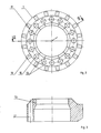
- Fig. 2 die Ansicht auf die Muffel des Brenners in Blickrichtung A und
- Fig. 3 den Schnitt III - III nach Fig. 2.
- 1 shows the longitudinal section through a burner according to the invention,
- Fig. 2 shows the view of the muffle of the burner in viewing direction A and
- 3 shows the section III - III according to FIG. 2.
Die Brenneranordnung besteht aus einem Luftkasten 1, durch den eine Brennerlanze 2 für Öl und mehrere Brennerlanzen 3 für Gas hindurchgeführt sind. Die Gasbrennerlanzen 3 sind um die Ölbrennerlanze 2 angeordnet. Auf der Ölbrennerlanze 2 ist ein Impeller 4 verschiebbar befestigt.The burner arrangement consists of an
Die Brennerlanzen 2, 3 sind von einem ersten Führungsrohr 5 umgeben, dessen Eintrittsöffnung innerhalb des Luftkastens 1 und dessen Austrittsöffnung 6 innerhalb der Brennermündung liegt, die durch die Brennerkehle 7 dargestellt ist. An die Brennerkehle 7 schließt sich ein Feuerraum 8 an. Der Luftkasten 1 ist von der Brennerkehle 7 durch eine Deckplatte 9 getrennt, durch die das erste Führungsrohr 5 hindurchragt.The
In rückwärtiger Verlängerung des ersten Führungsrohres 5 ist eine Dralleinrichtung 10 und ein Luftleitrohr 11 vorgesehen. Das Luftleitrohr 11 ist über ein nach außen geführtes Gestänge 12 axial verstellbar. In der einen Endstellung überdeckt das Luftleitrohr 11 den Lufteintrittsquerschnitt an der Dralleinrichtung 10. In der anderen Endstellung des Luftleitrohres 11 ist der Lufteintrittsquerschnitt an der Dralleinrichtung 10 freigegeben und der übrige Eintrittsquerschnitt zu dem ersten Führungsrohr überdeckt.A
Innerhalb der Brennerkehle 7 ist in der Längsachse des Brenners in einem axialen Abstand von der Austrittsöffnung 6 des ersten Führungsrohres 5 und der Deckplatte 9 des Luftkastens 1 ein weiteres Führungsrohr angeordnet.A further guide tube is arranged within the
Dieses weitere Führungsrohr besteht aus einer nichtmetallischen, keramischen Muffel 13 aus einem temperatur- und korrosionsbeständigen Werkstoff. Dieser Werkstoff kann rekristallisiertes Siliziumkarbid oder auch Stampfmasse sein. Die Muffel 13 ist aus Sektoren 14 aufgebaut, die an den Trennfugen 15 mit einem temperaturbeständigen Filz beklebt sind. Dabei bleiben die Sektoren 14 der Muffel 13 zueinander frei beweglich. Die so zusammengesetzten Sektoren 14 bilden einen selbsttragenden, ringförmigen Körper. Die Muffel 13 stützt sich über angeformte Arme 16 auf der Mauerung der Brennerkehle 7 ab und ist dort gegen ein axiales Verschieben gesichert. Die Sicherung erfolgt durch Verkleben oder durch keramische Befestigungselemente.This further guide tube consists of a non-metallic,
Die Muffel 13 ist mit axialen Durchtrittsöffnungen 17 versehen, durch die Rohre 18 hindurchgeführt sind. Die Rohre 18 durchdringen die Deckplatte 9 und ragen mit ihrem offenen Ende in den Luftkasten 1 hinein. Das andere Ende der Rohre 18 ragt über die Muffel 13 hinaus und in den Feuerraum 8 hinein. Dieses Ende der Rohre 18 kann abgeschrägt sein, wobei dann die Austrittskante parallel zu dem Sprühwinkel 19 des aus der Ölbrennerlanze 2 austretenden Ölstrahles verläuft.The
Die Rohre 18 können aus feuerfester Keramik, beispielsweise aus Aluminiumsilikat oder aus infiltriertem Siliziumkarbid gefertigt sein. Um Wärmespannungen aufnehmen zu können, werden die Rohre 18 im Bereich der Durchdringung der Muffel 13 von einem temperaturbeständigen Filz umhüllt. Alle keramischen Innenteile des Brenners sind derart konstruiert, daß ein Austausch vom Feuerraum 8 aus möglich ist und daß zeitraubende Demontagen des Luftkastens, der Brennstoffanschlußleitungen und andere entfallen.The
Claims (4)
Priority Applications (1)
| Application Number | Priority Date | Filing Date | Title |
|---|---|---|---|
| AT86113814T ATE51065T1 (en) | 1986-01-13 | 1986-10-06 | BURNERS FOR COMBUSTING FUELS WITH REDUCED FORMATION OF NITROUS OXIDES. |
Applications Claiming Priority (2)
| Application Number | Priority Date | Filing Date | Title |
|---|---|---|---|
| DE3600665 | 1986-01-13 | ||
| DE3600665A DE3600665C1 (en) | 1986-01-13 | 1986-01-13 | Burner for burning liquid and / or gaseous fuel with reduced formation of nitrogen oxides |
Publications (3)
| Publication Number | Publication Date |
|---|---|
| EP0229231A2 true EP0229231A2 (en) | 1987-07-22 |
| EP0229231A3 EP0229231A3 (en) | 1988-08-31 |
| EP0229231B1 EP0229231B1 (en) | 1990-03-14 |
Family
ID=6291710
Family Applications (1)
| Application Number | Title | Priority Date | Filing Date |
|---|---|---|---|
| EP86113814A Expired - Lifetime EP0229231B1 (en) | 1986-01-13 | 1986-10-06 | Burner for the combustion of fuels with reduced production of nitric oxides |
Country Status (3)
| Country | Link |
|---|---|
| EP (1) | EP0229231B1 (en) |
| AT (1) | ATE51065T1 (en) |
| DE (2) | DE3600665C1 (en) |
Cited By (1)
| Publication number | Priority date | Publication date | Assignee | Title |
|---|---|---|---|---|
| EP0893651A1 (en) * | 1997-07-22 | 1999-01-27 | Entreprise Generale De Chauffage Industriel Pillard | Burner for liquid and gaseous fuel with low nitric oxyde emission |
Families Citing this family (2)
| Publication number | Priority date | Publication date | Assignee | Title |
|---|---|---|---|---|
| GB2262981B (en) * | 1991-12-30 | 1995-08-09 | Ind Tech Res Inst | Dual fuel low nox burner |
| CZ308899B6 (en) * | 2020-12-22 | 2021-08-11 | Vysoké Učení Technické V Brně | Air box with flue gas recirculation |
Citations (5)
| Publication number | Priority date | Publication date | Assignee | Title |
|---|---|---|---|---|
| DE2731562A1 (en) * | 1977-06-17 | 1978-12-21 | Sonvico Ag Langnau Ing Bureau | BURNERS FOR LIQUID AND / OR GASEOUS FUELS |
| DE3041177A1 (en) * | 1979-11-02 | 1981-05-14 | Hague International, South Portland, Me. | BURNER |
| DE3048201A1 (en) * | 1980-12-20 | 1982-07-08 | L. & C. Steinmüller GmbH, 5270 Gummersbach | Burner for nitrogen-bearing fuels, with coaxial primary air ducts - has furnace gas recirculating ducts to these ducts, pref. entering at restriction |
| US4347052A (en) * | 1978-06-19 | 1982-08-31 | John Zink Company | Low NOX burner |
| US4475885A (en) * | 1983-07-28 | 1984-10-09 | Bloom Engineering Company, Inc. | Adjustable flame burner |
Family Cites Families (2)
| Publication number | Priority date | Publication date | Assignee | Title |
|---|---|---|---|---|
| AT358702B (en) * | 1975-01-27 | 1980-09-25 | Manich Leo | SWIRL BURNER FOR OIL AND / OR GAS OPERATION |
| DE3327597A1 (en) * | 1983-07-30 | 1985-02-07 | Deutsche Babcock Werke AG, 4200 Oberhausen | METHOD AND BURNER FOR BURNING LIQUID OR GASEOUS FUELS WITH REDUCED NOX PRODUCTION |
-
1986
- 1986-01-13 DE DE3600665A patent/DE3600665C1/en not_active Expired
- 1986-10-06 AT AT86113814T patent/ATE51065T1/en not_active IP Right Cessation
- 1986-10-06 DE DE8686113814T patent/DE3669581D1/en not_active Expired - Lifetime
- 1986-10-06 EP EP86113814A patent/EP0229231B1/en not_active Expired - Lifetime
Patent Citations (5)
| Publication number | Priority date | Publication date | Assignee | Title |
|---|---|---|---|---|
| DE2731562A1 (en) * | 1977-06-17 | 1978-12-21 | Sonvico Ag Langnau Ing Bureau | BURNERS FOR LIQUID AND / OR GASEOUS FUELS |
| US4347052A (en) * | 1978-06-19 | 1982-08-31 | John Zink Company | Low NOX burner |
| DE3041177A1 (en) * | 1979-11-02 | 1981-05-14 | Hague International, South Portland, Me. | BURNER |
| DE3048201A1 (en) * | 1980-12-20 | 1982-07-08 | L. & C. Steinmüller GmbH, 5270 Gummersbach | Burner for nitrogen-bearing fuels, with coaxial primary air ducts - has furnace gas recirculating ducts to these ducts, pref. entering at restriction |
| US4475885A (en) * | 1983-07-28 | 1984-10-09 | Bloom Engineering Company, Inc. | Adjustable flame burner |
Cited By (2)
| Publication number | Priority date | Publication date | Assignee | Title |
|---|---|---|---|---|
| EP0893651A1 (en) * | 1997-07-22 | 1999-01-27 | Entreprise Generale De Chauffage Industriel Pillard | Burner for liquid and gaseous fuel with low nitric oxyde emission |
| FR2766557A1 (en) * | 1997-07-22 | 1999-01-29 | Pillard Chauffage | LIQUID AND GASEOUS FUEL BURNERS WITH LOW EMISSION OF NITROGEN OXIDES |
Also Published As
| Publication number | Publication date |
|---|---|
| DE3669581D1 (en) | 1990-04-19 |
| ATE51065T1 (en) | 1990-03-15 |
| DE3600665C1 (en) | 1987-07-16 |
| EP0229231B1 (en) | 1990-03-14 |
| EP0229231A3 (en) | 1988-08-31 |
Similar Documents
| Publication | Publication Date | Title |
|---|---|---|
| EP0164576B1 (en) | Industrial burner for gaseous or liquid fuels | |
| DE2323382C3 (en) | Hydrogen sulfide gas burner | |
| DE3815382C2 (en) | Combustion chamber for a gas turbine engine | |
| DE2839703A1 (en) | RING-SHAPED DOUBLE BURNER | |
| DE970426C (en) | Cyclone combustion chamber for gas turbines | |
| WO1987001434A1 (en) | Device for burning oxidizable components in a carrier gas | |
| DE2836433C2 (en) | Recuperative burners for industrial furnaces | |
| EP0108888B1 (en) | Plant for the heat treatment of granular material | |
| DE2261596C3 (en) | ||
| DE3014269C2 (en) | Incinerator for the incineration of contaminants in exhaust air and waste substances | |
| EP0229231B1 (en) | Burner for the combustion of fuels with reduced production of nitric oxides | |
| DD204299A5 (en) | POWER BOILER HEATING WITH A MULTIPLE OF ENGINES | |
| DE2734922A1 (en) | METHOD AND DEVICE FOR COOLING EXHAUST MANIFOLD | |
| DE4008692A1 (en) | Forced draught oil burner mixer - has tapering tube bent radially inwards at forward end | |
| DE3310500C2 (en) | Burners for burning pulverulent fuels, in particular coal dust | |
| DE4011190A1 (en) | Recuperative burner for industrial plant | |
| DE3210368C2 (en) | ||
| EP0451662B1 (en) | Recuperative burner | |
| EP1286115A1 (en) | Thermal post-combustion installation | |
| EP0272369A2 (en) | Boiler for a low temperature heating system | |
| DE3312353C2 (en) | Pulverized coal burners | |
| CH681386A5 (en) | ||
| DE2425528A1 (en) | HOT BLAST STOVE | |
| DE2053805A1 (en) | Recuperative burner | |
| DE3904635A1 (en) | BOILER |
Legal Events
| Date | Code | Title | Description |
|---|---|---|---|
| PUAI | Public reference made under article 153(3) epc to a published international application that has entered the european phase |
Free format text: ORIGINAL CODE: 0009012 |
|
| AK | Designated contracting states |
Kind code of ref document: A2 Designated state(s): AT BE CH DE FR GB IT LI NL SE |
|
| PUAL | Search report despatched |
Free format text: ORIGINAL CODE: 0009013 |
|
| RHK1 | Main classification (correction) |
Ipc: F23D 17/00 |
|
| AK | Designated contracting states |
Kind code of ref document: A3 Designated state(s): AT BE CH DE FR GB IT LI NL SE |
|
| 17P | Request for examination filed |
Effective date: 19881019 |
|
| 17Q | First examination report despatched |
Effective date: 19890126 |
|
| GRAA | (expected) grant |
Free format text: ORIGINAL CODE: 0009210 |
|
| AK | Designated contracting states |
Kind code of ref document: B1 Designated state(s): AT BE CH DE FR GB IT LI NL SE |
|
| REF | Corresponds to: |
Ref document number: 51065 Country of ref document: AT Date of ref document: 19900315 Kind code of ref document: T |
|
| REF | Corresponds to: |
Ref document number: 3669581 Country of ref document: DE Date of ref document: 19900419 |
|
| ET | Fr: translation filed | ||
| RAP2 | Party data changed (patent owner data changed or rights of a patent transferred) |
Owner name: DEUTSCHE BABCOCK WERKE AKTIENGESELLSCHAFT |
|
| GBT | Gb: translation of ep patent filed (gb section 77(6)(a)/1977) | ||
| ITF | It: translation for a ep patent filed |
Owner name: STUDIO JAUMANN |
|
| BECN | Be: change of holder's name |
Effective date: 19900314 |
|
| PLBE | No opposition filed within time limit |
Free format text: ORIGINAL CODE: 0009261 |
|
| STAA | Information on the status of an ep patent application or granted ep patent |
Free format text: STATUS: NO OPPOSITION FILED WITHIN TIME LIMIT |
|
| 26N | No opposition filed | ||
| REG | Reference to a national code |
Ref country code: GB Ref legal event code: 732 |
|
| PGFP | Annual fee paid to national office [announced via postgrant information from national office to epo] |
Ref country code: GB Payment date: 19920901 Year of fee payment: 7 |
|
| PGFP | Annual fee paid to national office [announced via postgrant information from national office to epo] |
Ref country code: FR Payment date: 19920924 Year of fee payment: 7 |
|
| PGFP | Annual fee paid to national office [announced via postgrant information from national office to epo] |
Ref country code: CH Payment date: 19920929 Year of fee payment: 7 |
|
| PGFP | Annual fee paid to national office [announced via postgrant information from national office to epo] |
Ref country code: SE Payment date: 19920930 Year of fee payment: 7 Ref country code: BE Payment date: 19920930 Year of fee payment: 7 Ref country code: AT Payment date: 19920930 Year of fee payment: 7 |
|
| PGFP | Annual fee paid to national office [announced via postgrant information from national office to epo] |
Ref country code: NL Payment date: 19921031 Year of fee payment: 7 |
|
| PGFP | Annual fee paid to national office [announced via postgrant information from national office to epo] |
Ref country code: DE Payment date: 19930922 Year of fee payment: 8 |
|
| PG25 | Lapsed in a contracting state [announced via postgrant information from national office to epo] |
Ref country code: GB Effective date: 19931006 Ref country code: AT Effective date: 19931006 |
|
| PG25 | Lapsed in a contracting state [announced via postgrant information from national office to epo] |
Ref country code: SE Effective date: 19931007 |
|
| PG25 | Lapsed in a contracting state [announced via postgrant information from national office to epo] |
Ref country code: LI Effective date: 19931031 Ref country code: CH Effective date: 19931031 Ref country code: BE Effective date: 19931031 |
|
| BERE | Be: lapsed |
Owner name: DEUTSCHE BABCOCK WERKE A.G. Effective date: 19931031 |
|
| PG25 | Lapsed in a contracting state [announced via postgrant information from national office to epo] |
Ref country code: NL Effective date: 19940501 |
|
| GBPC | Gb: european patent ceased through non-payment of renewal fee |
Effective date: 19931006 |
|
| NLV4 | Nl: lapsed or anulled due to non-payment of the annual fee | ||
| PG25 | Lapsed in a contracting state [announced via postgrant information from national office to epo] |
Ref country code: FR Effective date: 19940630 |
|
| REG | Reference to a national code |
Ref country code: CH Ref legal event code: PL |
|
| REG | Reference to a national code |
Ref country code: FR Ref legal event code: ST |
|
| EUG | Se: european patent has lapsed |
Ref document number: 86113814.7 Effective date: 19940510 |
|
| PG25 | Lapsed in a contracting state [announced via postgrant information from national office to epo] |
Ref country code: DE Effective date: 19950701 |
|
| PG25 | Lapsed in a contracting state [announced via postgrant information from national office to epo] |
Ref country code: IT Free format text: LAPSE BECAUSE OF NON-PAYMENT OF DUE FEES;WARNING: LAPSES OF ITALIAN PATENTS WITH EFFECTIVE DATE BEFORE 2007 MAY HAVE OCCURRED AT ANY TIME BEFORE 2007. THE CORRECT EFFECTIVE DATE MAY BE DIFFERENT FROM THE ONE RECORDED. Effective date: 20051006 |