EP0229227A2 - Connecting rod design with voids - Google Patents
Connecting rod design with voids Download PDFInfo
- Publication number
- EP0229227A2 EP0229227A2 EP86113311A EP86113311A EP0229227A2 EP 0229227 A2 EP0229227 A2 EP 0229227A2 EP 86113311 A EP86113311 A EP 86113311A EP 86113311 A EP86113311 A EP 86113311A EP 0229227 A2 EP0229227 A2 EP 0229227A2
- Authority
- EP
- European Patent Office
- Prior art keywords
- connecting rod
- ring
- crankshaft
- portions
- voids
- Prior art date
- Legal status (The legal status is an assumption and is not a legal conclusion. Google has not performed a legal analysis and makes no representation as to the accuracy of the status listed.)
- Granted
Links
Images
Classifications
-
- F—MECHANICAL ENGINEERING; LIGHTING; HEATING; WEAPONS; BLASTING
- F16—ENGINEERING ELEMENTS AND UNITS; GENERAL MEASURES FOR PRODUCING AND MAINTAINING EFFECTIVE FUNCTIONING OF MACHINES OR INSTALLATIONS; THERMAL INSULATION IN GENERAL
- F16C—SHAFTS; FLEXIBLE SHAFTS; ELEMENTS OR CRANKSHAFT MECHANISMS; ROTARY BODIES OTHER THAN GEARING ELEMENTS; BEARINGS
- F16C7/00—Connecting-rods or like links pivoted at both ends; Construction of connecting-rod heads
- F16C7/02—Constructions of connecting-rods with constant length
- F16C7/023—Constructions of connecting-rods with constant length for piston engines, pumps or the like
-
- Y—GENERAL TAGGING OF NEW TECHNOLOGICAL DEVELOPMENTS; GENERAL TAGGING OF CROSS-SECTIONAL TECHNOLOGIES SPANNING OVER SEVERAL SECTIONS OF THE IPC; TECHNICAL SUBJECTS COVERED BY FORMER USPC CROSS-REFERENCE ART COLLECTIONS [XRACs] AND DIGESTS
- Y10—TECHNICAL SUBJECTS COVERED BY FORMER USPC
- Y10T—TECHNICAL SUBJECTS COVERED BY FORMER US CLASSIFICATION
- Y10T74/00—Machine element or mechanism
- Y10T74/21—Elements
- Y10T74/2142—Pitmans and connecting rods
- Y10T74/2144—Yieldable
-
- Y—GENERAL TAGGING OF NEW TECHNOLOGICAL DEVELOPMENTS; GENERAL TAGGING OF CROSS-SECTIONAL TECHNOLOGIES SPANNING OVER SEVERAL SECTIONS OF THE IPC; TECHNICAL SUBJECTS COVERED BY FORMER USPC CROSS-REFERENCE ART COLLECTIONS [XRACs] AND DIGESTS
- Y10—TECHNICAL SUBJECTS COVERED BY FORMER USPC
- Y10T—TECHNICAL SUBJECTS COVERED BY FORMER US CLASSIFICATION
- Y10T74/00—Machine element or mechanism
- Y10T74/21—Elements
- Y10T74/2142—Pitmans and connecting rods
- Y10T74/2162—Engine type
Definitions
- This invention relates generally to a connecting rod used for connecting together reciprocating and rotating members in reciprocating piston machines such as combustion engines and compressors. More specifically, the invention is directed to a connecting rod design which is adapted to have press-fitted within its piston pin ring and crankshaft bores either bearings or liners.
- the design allows the piston pin ring and crankshaft portions which form the bores of the connecting rod, to deform radially substantially uniformly during the press-fitting operation such that the liner or bearing press-fitted within the respective bores retain a substantially circular shape. This is due to the creation of equal radial resistive forces upon the liner or bearing.
- Connecting rods are designed with a piston pin ring portion and a crankshaft ring portion connected together by a connecting member which is connected to the outer periphery of each ring portion.
- the piston pin ring portion has a bore for receiving a bearing for rotatably receiving a piston pin
- the crankshaft ring portion has a bore for receiving a liner for rotationally receiving the crankshaft.
- the inside diameter of liners or cups after the press-fitting operation can be machined into a more uniform circular shape.
- this does not solve the problem because the non-uniform radial forces of the ring portions create uneven radial distortion at elevated temperatures.
- machining each liner or bearing bore requires another step in the manufacturing process which is considerably time consuming and costly. Therefore, the method of machining the inside diameter of the liners or cups after press-fitting is not satisfactory.
- the objects of the invention are obtained by providing voids adjoining the outer periphery of the piston pin and crankshaft ring portions. These voids allow the ring portions, when press-fitting a liner or bearing within them, to deform substantially radially uniformly such that the liner or bearing retains a substantially circular shape. In essence, the voids break up the reinforcement of the ring portions caused by the connecting member without decreasing the connecting rod strength.
- the voids allow the ring porions to expand at the connection substantially in the same manner as the rest of the ring portion thereby resulting in a more uniform circular structure for receiving a respective crankshaft or piston pin.
- the invention in one form thereof, provides a connecting rod for use in internal combustion engines.
- the rod has a piston pin ring portion and a crankshaft ring portion which are connected together by a load bearing member.
- Each ring portion has a bore therein.
- a plurality of voids are provided in the load bearing member adjoining the outer perimeter of the crankshaft ring portion.
- the invention in one form thereof, provides a connecting rod for use in an internal combustion engine and having a piston pin ring portion with a piston pin bore therein and a crankshaft ring portion with a crankshaft bore therein.
- the ring portions are connected together by a load bearing member which has a plurality of voids therein adjoining the outer perimeter of the piston pin ring portion.
- the invention in one form thereof, still further provides a connecting rod having a piston pin ring portion with a bore therein and a crankshaft ring portion having a bore therein.
- the two ring portions are connected together with three ribs and two web portions which extend between and interconnect the three ribs.
- a plurality of voids are provided within the web portions and between the ribs adjoining the outer perimeters of both ring portions.
- the connecting rod of the present invention is used for connecting together reciprocating and rotating members in combustion engines and compressors.
- connecting rod 10 is shown connected to piston 12 and crankshaft 14.
- a drawn cup bearing 18 is used in the connection between connecting rod 10 and piston 12.
- Drawn cup bearing 18 rotatably receives a piston pin 17 (shown in Fig. 4) which is mounted within yoke type thrust washer 19 and piston shoulders 20.
- Liner 16 is used in the connection between connecting rod 10 and crankshaft 14. Liner 16 receives within it and rotates about crankshaft cylindrical portion 22.
- roller bearings 23 may be used between liner 16 and cylindrical portion 22 for further decreasing rotational friction.
- the manner of assembling connecting rod 10 to crankshaft 14 with roller bearings 23 is further described in U.S. Patent No. 4,494,286 which is assigned to the assignee of record of the present invention and which is incorporated herein by reference.
- drawn cup bearing 18 has within it a plurality of roller bearings 26.
- Drawn cup bearing 18 has an outer cylindrical surface 28 which, at any given temperature, has a diameter slightly greater than the diameter of the piston pin bore 24 of connecting rod 10 at the same given temperature.
- Drawn cup bearing 18 is adapted to be press-fitted into piston pin bore 24, as shown in Fig. 8 such that the cup bearing outer cylindrical surface pushes radially outwardly and fits tightly within said piston pin bore 24.
- Drawn cup bearing 18 receives within it piston pin 17 and rotates therearound.
- Cylindrically shaped liner 16 has at one end thereof a liner lip 30.
- Liner 16 also has outer cylindrical surface 32, and a liner inner surface 36.
- liner 16 is adapted to be press-fitted into crankshaft ring bore 34 of connecting rod 10.
- the radial diameter of the liner outer surface 32 at any given temperature is slightly greater than the crankshaft ring bore 34 diameter at the same given temperature such that, when liner 16 is press-fitted into crankshaft ring bore 34, liner 16 pushes radially outward and is held tightly within the crankshaft ring bore 34.
- Roller bearings 23 can be used between liner innersurface 36 and crankshaft portion 22 as discussed above.
- cylindrical liner 16 receives and rotates about crankshaft cylindrical portion 22.
- Piston pin ring bore 24 is formed and located within a piston pin ring portion generally indicated as 38.
- Crankshaft ring bore 34 is formed and located within a crankshaft ring portion generally indicated as 40.
- Piston pin ring portion 38 has an outer peripheral surface 42 and crankshaft ring portion 40 has an outer peripheral surface 44.
- Piston pin ring portion outer peripheral surface 42, and crankshaft ring portion outer peripheral surface 44 are connected together by two outer ribs 46 and center rib 48.
- Center rib 48 is connected to outer peripheral surfaces 42 and 44 generally perpendicularly. In this fashion, center rib 48 is the major load carrying member, while the two outer ribs 46 provide stiffness for countering bending, twisting and carry a portion of the load.
- outer ribs 46 and center rib 48 are generally parallel to one another. Further, ribs 46 and 48 are generally coplanar with piston pin ring portion 38 and crankshaft ring portion 40.
- outer ribs 46 have an inner surface 50 and an outer surface 52.
- Center rib 48 has web connecting surfaces 54 on its two opposite sides.
- Webbing 56 extends between and connects together outer ribs 46 to center rib 48. More specifically, webbing 56 is connected to the outer ribs' inner surface 50 and the respective center rib web connecting surface 54.
- Webbing 56 is generally perpendicular to ribs 46 and 48 and also coplanar therewith.
- webbing portions 59 extend between ribs 48 and 46.
- Webbing portions 59 in essence are ribs which, by interconnecting outer ribs 46 to center rib 48, provide additional rigidity for countering bending and twisting.
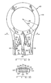
- R1 is the radius of the outer perimeter of ring portion 40.
- R2 which is smaller than Rl, represents the radius of the outer perimeter of ring portion 40 only at parts “B" of ring portion 40. Accordingly, parts “B” of ring portion 40 are thinner than the rest of ring portion 40. More specifically, parts “B” are adjacent to voids 58 and are thinner than the rest of ring portion 40. Parts “B” are thinner than the rest of ring portion 40 by the amount of Rl minus R2. In similar fashion, parts “B” of ring portion 38, as shown in Fig. 3, are also thinner than the rest of ring portion 38.
- Connecting rod 10 is made of a lightweight metal such as aluminum while the liner 16 and drawn cup bearing 18 are made of a material such as hardened or heat treated steel.
- Connecting rod 10 is generally cast or molded having ring portions 38 and 40 already connected with ribs 46 and 48 and with ribs 46 connected together by webbing 56.
- Voids 58 are also formed during the casting or molding of rod 10.
- Piston pin ring bore 24 and crankshaft ring bore 34 are machined thereafter so as to make substantially smooth circular bores.
- webbing 56 does not extend and is not connected to outer peripheral surfaces 42 and 44 and thus voids 58 are created. Because of voids 58, the outer peripheral surfaces 42 and 44 are connected together at three distinct points, namely, at the ends of outer ribs 46 and center rib 48.
- the present connecting rod design by utilizing voids 58 adjacent to peripheral surfaces 42 and 44 and by providing a thinner portion "B" adjacent voids 58, equalizes the cantilever resistive forces around ring portions 38 and 40 such that deformation of ring portions 38 and 40 are radially equivalent.
- parts "B” of ring portions 38 and 40 due to voids 58 and because parts “B” are thinner than the rest of ring portions 38 and 40, are allowed to deform and expand in the same fashion as the rest of the ring portions 38 and 40.
- outer ribs 46 at the connection to the outer peripheral surfaces 44 and 42, deform in the direction generally indicated by arrows "A".
- outer ribs 46 by deforming in the direction indicated by "A", provide a cantilever resistive force against direction "A”.
- the cantilever resistive force offsets the radial outward forces created through the press fitting operation and the resulting shape of ring portions 40 and 42 are substantially circular. That is, the radial deformation of piston pin ring bore 24 and crankshaft ring bore 34 is equal. Consequently, and more importantly, the resulting bores 24 and 34, after press-fitting the respective bearing 18 and liner 16, remain substantially circular.
- liner 16 and drawn cup bearing 18 also retain a substantially circular structure. It is therefore possible to provide a tighter clearance between the respective liner 16 or cup bearing 18 and crankshaft cylindrical portion 22 or piston pin 17. Further, by providing a more uniform circular fit, the forces transferred between connecting piston 12, rod 10, and crankshaft 14 are transferred more uniformly through bearing 18 and liner 16 and hence the life of the respective contacting members are substantially increased. In essence, the forces are more uniformly transferred over a larger surface area between piston 12 connecting rod 10 and crankshaft 14 through the respective larger contacting surfaces. Because the forces are distributed over larger surface areas, deformation of each member is also decreased during dynamic conditions.
Abstract
Description
- This invention relates generally to a connecting rod used for connecting together reciprocating and rotating members in reciprocating piston machines such as combustion engines and compressors. More specifically, the invention is directed to a connecting rod design which is adapted to have press-fitted within its piston pin ring and crankshaft bores either bearings or liners. The design allows the piston pin ring and crankshaft portions which form the bores of the connecting rod, to deform radially substantially uniformly during the press-fitting operation such that the liner or bearing press-fitted within the respective bores retain a substantially circular shape. This is due to the creation of equal radial resistive forces upon the liner or bearing.
- Connecting rods are designed with a piston pin ring portion and a crankshaft ring portion connected together by a connecting member which is connected to the outer periphery of each ring portion. The piston pin ring portion has a bore for receiving a bearing for rotatably receiving a piston pin, and the crankshaft ring portion has a bore for receiving a liner for rotationally receiving the crankshaft. Each ring portion is thus always reinforced and made stronger at the connecting area by the connecting member.
- In the past, when a liner or bearing was press-fitted within a respective bore of the ring portions, the forces created by the tight fit caused non-uniform radial deformation of the respective ring portions. This was caused by the reinforcement of the ring portions by the connecting member at the respective connecting areas of the ring portions. Stated differently, the ring portions were not allowed to deform uniformly upon the press-fitting because the connecting member resisted deformation of the ring portion at the connecting area. Since deformation generally occurred in the direction of least resistance, press-fitting a liner or a bearing within a ring portion bore caused the ring portions to take a generally non-circular shape. This was caused by the ring portion deforming radially more in the area of the ring portion which was not connected to the connecting member. Because of this non-uniform deformation, clearances between the crankshaft or piston pin and the bearings could not be held as close as desired. Accordingly, the life of the bearings and thus the combustion engine or compressor was considerably shortened. Further, the forces transferred between the connecting rod, piston, and the crankshaft were not transferred uniformly upon the full contacting surfaces and hence the life of the liners, bearings, connecting rod, piston pin and crankshaft were substantially limited.
- The inside diameter of liners or cups after the press-fitting operation can be machined into a more uniform circular shape. However, this does not solve the problem because the non-uniform radial forces of the ring portions create uneven radial distortion at elevated temperatures. Further, machining each liner or bearing bore requires another step in the manufacturing process which is considerably time consuming and costly. Therefore, the method of machining the inside diameter of the liners or cups after press-fitting is not satisfactory.
- It is the principal object of the invention to overcome the above-discussed disadvantages associated with earlier connecting rods. It is also the object of this invention to provide an economical connecting rod construction which has a uniform circular bore after the press-fitting of a liner or cup bearing for receiving a piston pin and a crankshaft., By providing a more circular bore after the press-fitting step than was possible with prior art connecting rods, tighter clearances may be attained between the crankshaft or piston pin and the liner or bearing. Thus, the life of the reciprocating and rotating members will be increased because the tighter clearances decrease wear. The tighter clearances also increase the contacting surface area between respective parts such that forces transferred between the parts are more evenly distributed. Further, the tighter clearances substantially reduce mechanical noise.
- The objects of the invention are obtained by providing voids adjoining the outer periphery of the piston pin and crankshaft ring portions. These voids allow the ring portions, when press-fitting a liner or bearing within them, to deform substantially radially uniformly such that the liner or bearing retains a substantially circular shape. In essence, the voids break up the reinforcement of the ring portions caused by the connecting member without decreasing the connecting rod strength. The voids allow the ring porions to expand at the connection substantially in the same manner as the rest of the ring portion thereby resulting in a more uniform circular structure for receiving a respective crankshaft or piston pin. By providing a more uniform circular shape, tighter clearances can be provided and forces are more uniformly distributed such that the life of all the working parts are substantially increased with no added production cost.
- The invention, in one form thereof, provides a connecting rod for use in internal combustion engines. The rod has a piston pin ring portion and a crankshaft ring portion which are connected together by a load bearing member. Each ring portion has a bore therein. A plurality of voids are provided in the load bearing member adjoining the outer perimeter of the crankshaft ring portion.
- The invention, in one form thereof, provides a connecting rod for use in an internal combustion engine and having a piston pin ring portion with a piston pin bore therein and a crankshaft ring portion with a crankshaft bore therein. The ring portions are connected together by a load bearing member which has a plurality of voids therein adjoining the outer perimeter of the piston pin ring portion.
- The invention, in one form thereof, still further provides a connecting rod having a piston pin ring portion with a bore therein and a crankshaft ring portion having a bore therein. The two ring portions are connected together with three ribs and two web portions which extend between and interconnect the three ribs. A plurality of voids are provided within the web portions and between the ribs adjoining the outer perimeters of both ring portions.
- The above-mentioned and other features and objects of this invention and the manner of obtaining them will become more apparent, and the invention itself will be better understood by reference to the following description of an embodiment of the invention, taken in conjunction with the accompanying drawings, wherein:
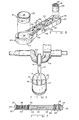
- Fig. 1 is a perspective view showing a connecting rod assembled to a piston and a crankshaft;
- Fig. 2 is a perspective view of a connecting rod according to the present invention assembled with a press-fitted liner and a drawn cup bearing;
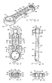
- Fig. 3 is a front elevational view of the connecting rod of Fig. 2 showing the webbing, voids, ribs, ring portions, a liner with roller bearings and a drawn cup bearing;
- Fig. 4 is a side elevational view of the connecting rod of Fig. 2 showing, with hidden lines, the webbing, liner and the drawn cup bearing;
- Fig. 5 is a cross-sectional view taken along line 5-5 of Fig. 3 showing the webbing and ribs;
- Fig. 6 is a cross-sectional view taken along line 6-6 of Fig. 3 showing the ribs and voids adjacent to the crankshaft ring portion;
- Fig. 7 is a cross-sectional view of the connecting rod along line 7-7 of Fig. 3 showing the the liner and drawn cup bearing along with the inner periphery of the crankshaft and piston pin ring bores;
- Fig. 8 is an exploded perspective view of the connecting rod of Fig. 2 together with a liner and a cup bearing;
- Fig. 9 is an enlarged front elevational view of a ring portion according to the present invention showing the ring portion adjoining the voids and ribs;
- Fig. 10 is cross-sectional view taken along lines 10-10 of Fig. 3 showing the thicker web portions.
- Corresponding reference characters indicate corresponding parts throughout the several views of the drawings.
- The exemplifications set out herein illustrate a preferred embodiment of the invention, in one form thereof, and such exemplifications are not to be construed as limiting the scope of the disclosure or the scope of the invention in any manner.
- As shown in Fig. 1 of the drawings, the connecting rod of the present invention is used for connecting together reciprocating and rotating members in combustion engines and compressors.
- More specifically, referring to Fig. 1, connecting
rod 10 is shown connected topiston 12 andcrankshaft 14. A drawn cup bearing 18 is used in the connection between connectingrod 10 andpiston 12. Drawn cup bearing 18 rotatably receives a piston pin 17 (shown in Fig. 4) which is mounted within yoketype thrust washer 19 andpiston shoulders 20. This structure is further described in U.S. Patent No. 4,549,445 assigned to the assignee of record of the present invention and which is incorporated herein by reference.Liner 16 is used in the connection between connectingrod 10 andcrankshaft 14.Liner 16 receives within it and rotates about crankshaftcylindrical portion 22. As shown in Figs. 3 and 7,roller bearings 23 may be used betweenliner 16 andcylindrical portion 22 for further decreasing rotational friction. The manner of assembling connectingrod 10 tocrankshaft 14 withroller bearings 23 is further described in U.S. Patent No. 4,494,286 which is assigned to the assignee of record of the present invention and which is incorporated herein by reference. - Now referring to Figs. 2-4 and 7 and 8, drawn cup bearing 18 has within it a plurality of
roller bearings 26. Drawn cup bearing 18 has an outercylindrical surface 28 which, at any given temperature, has a diameter slightly greater than the diameter of the piston pin bore 24 of connectingrod 10 at the same given temperature. Drawn cup bearing 18 is adapted to be press-fitted intopiston pin bore 24, as shown in Fig. 8 such that the cup bearing outer cylindrical surface pushes radially outwardly and fits tightly within saidpiston pin bore 24. Drawn cup bearing 18 receives within itpiston pin 17 and rotates therearound. - Cylindrically shaped
liner 16 has at one end thereof aliner lip 30.Liner 16 also has outercylindrical surface 32, and a linerinner surface 36. As shown in Fig. 8,liner 16 is adapted to be press-fitted into crankshaft ring bore 34 of connectingrod 10. The radial diameter of the linerouter surface 32 at any given temperature is slightly greater than the crankshaft ring bore 34 diameter at the same given temperature such that, whenliner 16 is press-fitted into crankshaft ring bore 34,liner 16 pushes radially outward and is held tightly within the crankshaft ring bore 34.Roller bearings 23 can be used between liner innersurface 36 andcrankshaft portion 22 as discussed above. Thus,cylindrical liner 16 receives and rotates about crankshaftcylindrical portion 22. - Piston pin ring bore 24 is formed and located within a piston pin ring portion generally indicated as 38. Crankshaft ring bore 34 is formed and located within a crankshaft ring portion generally indicated as 40. Piston
pin ring portion 38 has an outerperipheral surface 42 andcrankshaft ring portion 40 has an outerperipheral surface 44. Piston pin ring portion outerperipheral surface 42, and crankshaft ring portion outerperipheral surface 44 are connected together by twoouter ribs 46 andcenter rib 48.Center rib 48 is connected to outerperipheral surfaces center rib 48 is the major load carrying member, while the twoouter ribs 46 provide stiffness for countering bending, twisting and carry a portion of the load. As shown in the drawings,outer ribs 46 andcenter rib 48 are generally parallel to one another. Further,ribs pin ring portion 38 andcrankshaft ring portion 40. - Referring now, more specifically, to Figs. 5, 6 and 10
outer ribs 46 have aninner surface 50 and anouter surface 52.Center rib 48 hasweb connecting surfaces 54 on its two opposite sides.Webbing 56 extends between and connects togetherouter ribs 46 to centerrib 48. More specifically, webbing 56 is connected to the outer ribs'inner surface 50 and the respective center ribweb connecting surface 54.Webbing 56 is generally perpendicular toribs - At the ends of
webs 56, betweenribs ring portions voids 58. At the end ofwebs 56 adjoiningvoids 58,thicker webbing portions 59 extend betweenribs Webbing portions 59 in essence are ribs which, by interconnectingouter ribs 46 to centerrib 48, provide additional rigidity for countering bending and twisting. - Referring to Fig. 9,
ring portion 40 is shown enlarged. R1 is the radius of the outer perimeter ofring portion 40. R2, which is smaller than Rl, represents the radius of the outer perimeter ofring portion 40 only at parts "B" ofring portion 40. Accordingly, parts "B" ofring portion 40 are thinner than the rest ofring portion 40. More specifically, parts "B" are adjacent to voids 58 and are thinner than the rest ofring portion 40. Parts "B" are thinner than the rest ofring portion 40 by the amount of Rl minus R2. In similar fashion, parts "B" ofring portion 38, as shown in Fig. 3, are also thinner than the rest ofring portion 38. - Connecting
rod 10 is made of a lightweight metal such as aluminum while theliner 16 and drawn cup bearing 18 are made of a material such as hardened or heat treated steel. Connectingrod 10 is generally cast or molded havingring portions ribs ribs 46 connected together by webbing 56.Voids 58 are also formed during the casting or molding ofrod 10. Piston pin ring bore 24 and crankshaft ring bore 34 are machined thereafter so as to make substantially smooth circular bores. As shown in Fig. 3, webbing 56 does not extend and is not connected to outerperipheral surfaces voids 58, the outerperipheral surfaces outer ribs 46 andcenter rib 48. - When press-fitting
liner 16 and drawn cup bearing 18, within their respective bores, radially outward forces are placed on the pistonpin ring portion 38 andcrankshaft ring portion 40. These radial forces causering portions voids 58 adjacent toperipheral surfaces adjacent voids 58, equalizes the cantilever resistive forces aroundring portions ring portions ring portions voids 58 and because parts "B" are thinner than the rest ofring portions ring portions outer ribs 46, at the connection to the outerperipheral surfaces outer ribs 46, by deforming in the direction indicated by "A", provide a cantilever resistive force against direction "A". However, the cantilever resistive force offsets the radial outward forces created through the press fitting operation and the resulting shape ofring portions respective bearing 18 andliner 16, remain substantially circular. - By retaining substantially
circular bores liner 16 and drawn cup bearing 18 also retain a substantially circular structure. It is therefore possible to provide a tighter clearance between therespective liner 16 or cup bearing 18 and crankshaftcylindrical portion 22 orpiston pin 17. Further, by providing a more uniform circular fit, the forces transferred between connectingpiston 12,rod 10, andcrankshaft 14 are transferred more uniformly through bearing 18 andliner 16 and hence the life of the respective contacting members are substantially increased. In essence, the forces are more uniformly transferred over a larger surface area betweenpiston 12 connectingrod 10 andcrankshaft 14 through the respective larger contacting surfaces. Because the forces are distributed over larger surface areas, deformation of each member is also decreased during dynamic conditions. Since each member, through a more uniform circular fit, deforms less during dynamic conditions, the life of each respective member is also increased. Further yet, because the forces are more evenly distributed over larger surface areas, uneven physical wear due to friction is substantially decreased. Thus, the connecting rod design disclosed herein substantially increases the life ofliner 16, drawn cup bearing 18, connectingrod 10,piston pin 17 andcrankshaft 14. - While the invention has been described as having a specific embodiment, it will be understood that it is capable of further modification. This application is, therefore, intended to cover any variations, uses, or adaptations of the invention following the general principles thereof and including such departures from the present disclosure as come within known or customary practice in the art to which this invention pertains and fall within the limits of the appended claims.
Claims (6)
Applications Claiming Priority (2)
| Application Number | Priority Date | Filing Date | Title |
|---|---|---|---|
| US06/816,208 US4691590A (en) | 1986-01-06 | 1986-01-06 | Connecting rod design with voids |
| US816208 | 1986-01-06 |
Publications (3)
| Publication Number | Publication Date |
|---|---|
| EP0229227A2 true EP0229227A2 (en) | 1987-07-22 |
| EP0229227A3 EP0229227A3 (en) | 1988-01-07 |
| EP0229227B1 EP0229227B1 (en) | 1989-04-12 |
Family
ID=25219971
Family Applications (1)
| Application Number | Title | Priority Date | Filing Date |
|---|---|---|---|
| EP86113311A Expired EP0229227B1 (en) | 1986-01-06 | 1986-09-26 | Connecting rod design with voids |
Country Status (5)
| Country | Link |
|---|---|
| US (1) | US4691590A (en) |
| EP (1) | EP0229227B1 (en) |
| JP (1) | JPS62167916A (en) |
| CA (1) | CA1263924A (en) |
| DE (1) | DE3662807D1 (en) |
Cited By (2)
| Publication number | Priority date | Publication date | Assignee | Title |
|---|---|---|---|---|
| EP1054173A1 (en) * | 1999-05-21 | 2000-11-22 | Hutchinson | Connecting rod for limiting relative movement between two rigid elements |
| WO2015149872A1 (en) * | 2014-04-04 | 2015-10-08 | Howden Thomassen Compressors Bv | Connecting rod with modified end |
Families Citing this family (27)
| Publication number | Priority date | Publication date | Assignee | Title |
|---|---|---|---|---|
| JPH01104424U (en) * | 1987-12-29 | 1989-07-14 | ||
| JPH02116018U (en) * | 1989-03-07 | 1990-09-17 | ||
| JP3406039B2 (en) * | 1993-12-27 | 2003-05-12 | ヤマハ発動機株式会社 | Engine supercharger |
| JPH08312632A (en) * | 1995-05-17 | 1996-11-26 | Outboard Marine Corp | Connecting rod and crank shaft assembly |
| US5617820A (en) * | 1995-10-17 | 1997-04-08 | General Motors Corporation | Connecting rod for internal combustion engine |
| US5673666A (en) * | 1995-10-17 | 1997-10-07 | General Motors Corporation | Connecting rod for internal combustion engine |
| JPH09209891A (en) * | 1996-02-08 | 1997-08-12 | Denso Corp | Starter |
| US6371009B1 (en) * | 1997-11-13 | 2002-04-16 | Daniel L. Cobble | Structural matrix for a piston and connecting-rod assembly |
| US6349688B1 (en) | 2000-02-18 | 2002-02-26 | Briggs & Stratton Corporation | Direct lever overhead valve system |
| AT409657B (en) * | 2000-09-26 | 2002-10-25 | Miba Sintermetall Ag | SINDERED CONNECTING ROD FOR AN INTERNAL COMBUSTION ENGINE |
| DE10141653B4 (en) * | 2001-08-24 | 2020-08-27 | Schaeffler Technologies AG & Co. KG | Connecting rod of a crank drive |
| US6874458B2 (en) | 2001-12-28 | 2005-04-05 | Kohler Co. | Balance system for single cylinder engine |
| US6739304B2 (en) | 2002-06-28 | 2004-05-25 | Kohler Co. | Cross-flow cylinder head |
| US6732701B2 (en) | 2002-07-01 | 2004-05-11 | Kohler Co. | Oil circuit for twin cam internal combustion engine |
| US6684846B1 (en) | 2002-07-18 | 2004-02-03 | Kohler Co. | Crankshaft oil circuit |
| US6837206B2 (en) | 2002-07-11 | 2005-01-04 | Kohler Co. | Crankcase cover with oil passages |
| US6978751B2 (en) | 2002-07-18 | 2005-12-27 | Kohler Co. | Cam follower arm for an internal combustion engine |
| US6742488B2 (en) | 2002-07-18 | 2004-06-01 | Kohler Co. | Component for governing air flow in and around cylinder head port |
| US6837207B2 (en) | 2002-07-18 | 2005-01-04 | Kohler Co. | Inverted crankcase with attachments for an internal combustion engine |
| US6752846B2 (en) | 2002-07-18 | 2004-06-22 | Kohler Co. | Panel type air filter element with integral baffle |
| EP1450056B1 (en) * | 2003-02-19 | 2017-06-07 | Nissan Motor Co., Ltd. | High-strength connecting rod and method of producing same |
| AT501810B1 (en) * | 2005-05-11 | 2007-02-15 | O St Feingussgesellschaft M B | HIGH ROBUST, LIGHTWEIGHT CONNECTING ROD |
| MX2008000881A (en) * | 2005-07-21 | 2008-03-26 | Gkn Sinter Metals Inc | Connecting rod with cast-in insert. |
| MX2011009552A (en) * | 2009-03-16 | 2011-10-12 | Kessler Kg Maschf | Method for joining two components of a unit. |
| JP6168523B2 (en) * | 2014-02-05 | 2017-07-26 | 本田技研工業株式会社 | Power transmission device for vehicle |
| WO2017170913A1 (en) * | 2016-03-30 | 2017-10-05 | Ntn株式会社 | Connecting rod, connecting rod module, and method for manufacturing same |
| US11629751B2 (en) | 2019-06-12 | 2023-04-18 | Achates Power, Inc. | Connecting rod assembly |
Citations (6)
| Publication number | Priority date | Publication date | Assignee | Title |
|---|---|---|---|---|
| US3149503A (en) * | 1959-11-10 | 1964-09-22 | Daimler Benz Ag | Connecting rod construction |
| GB1094950A (en) * | 1965-12-01 | 1967-12-13 | Gen Motors Corp | Connecting rods |
| JPS5923119A (en) * | 1982-07-30 | 1984-02-06 | Ryobi Ltd | Connecting rod of die casting alumnum alloy |
| DE3238489A1 (en) * | 1982-10-18 | 1984-04-19 | Fa. Andreas Stihl, 7050 Waiblingen | Connecting rod |
| JPS5977117A (en) * | 1982-10-22 | 1984-05-02 | Toyota Central Res & Dev Lab Inc | Connecting rod of internal-combustion engine and manufacture thereof |
| EP0108543A1 (en) * | 1982-10-25 | 1984-05-16 | Tecumseh Products Company | Assembly of connecting rod and crankshaft |
Family Cites Families (22)
| Publication number | Priority date | Publication date | Assignee | Title |
|---|---|---|---|---|
| US2733782A (en) * | 1956-02-07 | Brake hanger | ||
| US683553A (en) * | 1901-08-15 | 1901-10-01 | Ernst H Huenefeld | Washing-machine. |
| US1427788A (en) * | 1921-12-08 | 1922-09-05 | Drevitson Carl Bruno | Connecting rod |
| DE412596C (en) * | 1922-10-19 | 1925-04-24 | Helmut Von Bezold Dipl Ing | Connecting rod with separate connecting rod shaft and crank pin roller bearing |
| US1895467A (en) * | 1930-05-24 | 1933-01-31 | United Shoe Machinery Corp | Art of making shoe stiffeners |
| US1995835A (en) * | 1932-11-04 | 1935-03-26 | Timken Roller Bearing Co | Connecting rod |
| US2084188A (en) * | 1933-08-17 | 1937-06-15 | Pennsyivania Crusher Company | Jaw crusher |
| FR854061A (en) * | 1938-12-07 | 1940-04-04 | Mawen | Perfected connecting rod |
| GB724067A (en) * | 1951-12-28 | 1955-02-16 | Daimler Benz Ag | Improvements relating to engine connecting rods |
| US2716578A (en) * | 1953-02-27 | 1955-08-30 | Curtiss Wright Corp | Split connecting rod construction |
| US2890598A (en) * | 1954-04-17 | 1959-06-16 | Daimler Benz Ag | Connecting rod |
| GB898268A (en) * | 1959-11-06 | 1962-06-06 | Daimler Benz Ag | Improvements relating to big-ends for connecting rods |
| US2995953A (en) * | 1959-12-07 | 1961-08-15 | Fazi Fulvio De | Connecting rod for engine |
| DE1210263B (en) * | 1964-07-23 | 1966-02-03 | Karl Schmidt Ges Mit Beschraen | Connecting rod with cast oil pipe |
| US3285098A (en) * | 1965-03-22 | 1966-11-15 | Beveridge John Herbert | Connecting rod for reciprocating piston machine |
| US3559503A (en) * | 1969-01-27 | 1971-02-02 | Elsbett L | Connecting rod for high power piston engines |
| US3739657A (en) * | 1972-01-07 | 1973-06-19 | Allis Chalmers | Connecting rod lubrication oil hole |
| SE404764B (en) * | 1976-04-28 | 1978-10-30 | Volvo Penta Ab | FABRICS AND PROCEDURE AND CAST FORM FOR MANUFACTURE OF FABRICS |
| DE2807298A1 (en) * | 1978-02-21 | 1979-08-23 | Daimler Benz Ag | Compact piston rod for V=engine - has narrow cross=section at big end for close spacing between cylinders |
| DE3004575A1 (en) * | 1980-02-08 | 1981-08-13 | Sigri Elektrographit Gmbh, 8901 Meitingen | CONNECTING ROD MADE OF COMPOSITE MATERIAL |
| JPS57165146A (en) * | 1981-04-03 | 1982-10-12 | Toyota Motor Corp | Production for connecting rod for engine |
| US4549445A (en) * | 1983-12-12 | 1985-10-29 | Tecumseh Products Company | Yoke thrust bearing for a piston and connecting rod assembly |
-
1986
- 1986-01-06 US US06/816,208 patent/US4691590A/en not_active Expired - Lifetime
- 1986-09-24 CA CA000518952A patent/CA1263924A/en not_active Expired
- 1986-09-26 DE DE8686113311T patent/DE3662807D1/en not_active Expired
- 1986-09-26 EP EP86113311A patent/EP0229227B1/en not_active Expired
- 1986-11-01 JP JP61261754A patent/JPS62167916A/en active Granted
Patent Citations (6)
| Publication number | Priority date | Publication date | Assignee | Title |
|---|---|---|---|---|
| US3149503A (en) * | 1959-11-10 | 1964-09-22 | Daimler Benz Ag | Connecting rod construction |
| GB1094950A (en) * | 1965-12-01 | 1967-12-13 | Gen Motors Corp | Connecting rods |
| JPS5923119A (en) * | 1982-07-30 | 1984-02-06 | Ryobi Ltd | Connecting rod of die casting alumnum alloy |
| DE3238489A1 (en) * | 1982-10-18 | 1984-04-19 | Fa. Andreas Stihl, 7050 Waiblingen | Connecting rod |
| JPS5977117A (en) * | 1982-10-22 | 1984-05-02 | Toyota Central Res & Dev Lab Inc | Connecting rod of internal-combustion engine and manufacture thereof |
| EP0108543A1 (en) * | 1982-10-25 | 1984-05-16 | Tecumseh Products Company | Assembly of connecting rod and crankshaft |
Non-Patent Citations (2)
| Title |
|---|
| PATENT ABSTRACTS OF JAPAN, vol. 8, no. 116 (M-299)[1553], 30th May 1984; & JP-A-59 023 119 (RYOBI K.K.) 06-02-1984 * |
| PATENT ABSTRACTS OF JAPAN, vol. 8, no. 186 (M-320)[1623], 25th August 1984; & JP-A-59 077 117 (TOYODA CHUO KENKYUSHO K.K.) 02-05-1984 * |
Cited By (5)
| Publication number | Priority date | Publication date | Assignee | Title |
|---|---|---|---|---|
| EP1054173A1 (en) * | 1999-05-21 | 2000-11-22 | Hutchinson | Connecting rod for limiting relative movement between two rigid elements |
| FR2793854A1 (en) * | 1999-05-21 | 2000-11-24 | Hutchinson | CONNECTING ROD TO LIMIT RELATIVE TRAVELS BETWEEN TWO RIGID ELEMENTS |
| US6457380B1 (en) | 1999-05-21 | 2002-10-01 | Hutchinson | Connecting rod intended to limit relative movements between two rigid components |
| WO2015149872A1 (en) * | 2014-04-04 | 2015-10-08 | Howden Thomassen Compressors Bv | Connecting rod with modified end |
| US10215167B2 (en) | 2014-04-04 | 2019-02-26 | Howden Thomassen Compressors Bv | Connecting rod with modified end |
Also Published As
| Publication number | Publication date |
|---|---|
| JPS62167916A (en) | 1987-07-24 |
| JPH0438930B2 (en) | 1992-06-26 |
| CA1263924A (en) | 1989-12-19 |
| EP0229227B1 (en) | 1989-04-12 |
| EP0229227A3 (en) | 1988-01-07 |
| US4691590A (en) | 1987-09-08 |
| DE3662807D1 (en) | 1989-05-18 |
Similar Documents
| Publication | Publication Date | Title |
|---|---|---|
| US4691590A (en) | Connecting rod design with voids | |
| US5293684A (en) | Reduced material crankshaft fabrication | |
| US4612695A (en) | Method of manufacturing a hollow cam shaft | |
| AU4372793A (en) | Cage for roller bearings | |
| CA1326962C (en) | Driveshaft with driving elements attached to it in groups | |
| JP2617583B2 (en) | Split ring roller bearing cage | |
| US5407282A (en) | Single-trust bearing | |
| CA1202794A (en) | Universal joint | |
| US3244463A (en) | Hardened liner for anti-friction bearing and split housing | |
| JP2807761B2 (en) | Manufacturing method of crankshaft | |
| US20030053727A1 (en) | Roller bearing cage | |
| CN1026559C (en) | Method for making assembled crank-shafts by enlarging sleeves pivoted in seperated plugs | |
| US3958431A (en) | Universal joint and method for making the same | |
| CA1136683A (en) | Connecting-rod bearing | |
| JPH07259838A (en) | Manufacture of crankshaft | |
| US5197188A (en) | Process for producing assembled crankshafts by expanding sleeves arranged in divided journals | |
| WO1993015329A1 (en) | Bearing split outer ring and method of assembly | |
| US20040081381A1 (en) | Method and assemblies utilizing a drawn race in a compression bearing assembly | |
| US6820518B2 (en) | Crankshaft assembly | |
| EP0234625A1 (en) | Wrist pin | |
| US2978284A (en) | Piston head structure | |
| JPH02180308A (en) | Cast crank shaft for internal combustion engine | |
| CN111886084A (en) | Parking lock | |
| JPS63115926U (en) | ||
| JP2586978Y2 (en) | Cast iron crankshaft |
Legal Events
| Date | Code | Title | Description |
|---|---|---|---|
| PUAI | Public reference made under article 153(3) epc to a published international application that has entered the european phase |
Free format text: ORIGINAL CODE: 0009012 |
|
| AK | Designated contracting states |
Kind code of ref document: A2 Designated state(s): DE FR GB IT |
|
| PUAL | Search report despatched |
Free format text: ORIGINAL CODE: 0009013 |
|
| AK | Designated contracting states |
Kind code of ref document: A3 Designated state(s): DE FR GB IT |
|
| 17P | Request for examination filed |
Effective date: 19880224 |
|
| 17Q | First examination report despatched |
Effective date: 19880510 |
|
| GRAA | (expected) grant |
Free format text: ORIGINAL CODE: 0009210 |
|
| AK | Designated contracting states |
Kind code of ref document: B1 Designated state(s): DE FR GB IT |
|
| REF | Corresponds to: |
Ref document number: 3662807 Country of ref document: DE Date of ref document: 19890518 |
|
| ET | Fr: translation filed | ||
| ITF | It: translation for a ep patent filed |
Owner name: STUDIO TORTA SOCIETA' SEMPLICE |
|
| PLBE | No opposition filed within time limit |
Free format text: ORIGINAL CODE: 0009261 |
|
| STAA | Information on the status of an ep patent application or granted ep patent |
Free format text: STATUS: NO OPPOSITION FILED WITHIN TIME LIMIT |
|
| 26N | No opposition filed | ||
| ITTA | It: last paid annual fee | ||
| PGFP | Annual fee paid to national office [announced via postgrant information from national office to epo] |
Ref country code: GB Payment date: 19990823 Year of fee payment: 14 Ref country code: DE Payment date: 19990823 Year of fee payment: 14 |
|
| PG25 | Lapsed in a contracting state [announced via postgrant information from national office to epo] |
Ref country code: GB Free format text: LAPSE BECAUSE OF NON-PAYMENT OF DUE FEES Effective date: 20000926 |
|
| GBPC | Gb: european patent ceased through non-payment of renewal fee |
Effective date: 20000926 |
|
| PG25 | Lapsed in a contracting state [announced via postgrant information from national office to epo] |
Ref country code: DE Free format text: LAPSE BECAUSE OF NON-PAYMENT OF DUE FEES Effective date: 20010601 |
|
| PGFP | Annual fee paid to national office [announced via postgrant information from national office to epo] |
Ref country code: FR Payment date: 20040819 Year of fee payment: 19 |
|
| PG25 | Lapsed in a contracting state [announced via postgrant information from national office to epo] |
Ref country code: IT Free format text: LAPSE BECAUSE OF NON-PAYMENT OF DUE FEES;WARNING: LAPSES OF ITALIAN PATENTS WITH EFFECTIVE DATE BEFORE 2007 MAY HAVE OCCURRED AT ANY TIME BEFORE 2007. THE CORRECT EFFECTIVE DATE MAY BE DIFFERENT FROM THE ONE RECORDED. Effective date: 20050926 |
|
| PG25 | Lapsed in a contracting state [announced via postgrant information from national office to epo] |
Ref country code: FR Free format text: LAPSE BECAUSE OF NON-PAYMENT OF DUE FEES Effective date: 20060531 |
|
| REG | Reference to a national code |
Ref country code: FR Ref legal event code: ST Effective date: 20060531 |