EP0228683A2 - Kostengünstiger, zwischenliegender Strahlenschild für ein Magnetkryostat - Google Patents
Kostengünstiger, zwischenliegender Strahlenschild für ein Magnetkryostat Download PDFInfo
- Publication number
- EP0228683A2 EP0228683A2 EP86117782A EP86117782A EP0228683A2 EP 0228683 A2 EP0228683 A2 EP 0228683A2 EP 86117782 A EP86117782 A EP 86117782A EP 86117782 A EP86117782 A EP 86117782A EP 0228683 A2 EP0228683 A2 EP 0228683A2
- Authority
- EP
- European Patent Office
- Prior art keywords
- shield
- cryostat
- vessel
- helium vessel
- penetration
- Prior art date
- Legal status (The legal status is an assumption and is not a legal conclusion. Google has not performed a legal analysis and makes no representation as to the accuracy of the status listed.)
- Ceased
Links
Images



Classifications
-
- F—MECHANICAL ENGINEERING; LIGHTING; HEATING; WEAPONS; BLASTING
- F17—STORING OR DISTRIBUTING GASES OR LIQUIDS
- F17C—VESSELS FOR CONTAINING OR STORING COMPRESSED, LIQUEFIED OR SOLIDIFIED GASES; FIXED-CAPACITY GAS-HOLDERS; FILLING VESSELS WITH, OR DISCHARGING FROM VESSELS, COMPRESSED, LIQUEFIED, OR SOLIDIFIED GASES
- F17C3/00—Vessels not under pressure
- F17C3/02—Vessels not under pressure with provision for thermal insulation
- F17C3/08—Vessels not under pressure with provision for thermal insulation by vacuum spaces, e.g. Dewar flask
- F17C3/085—Cryostats
-
- G—PHYSICS
- G01—MEASURING; TESTING
- G01R—MEASURING ELECTRIC VARIABLES; MEASURING MAGNETIC VARIABLES
- G01R33/00—Arrangements or instruments for measuring magnetic variables
- G01R33/20—Arrangements or instruments for measuring magnetic variables involving magnetic resonance
- G01R33/28—Details of apparatus provided for in groups G01R33/44 - G01R33/64
- G01R33/38—Systems for generation, homogenisation or stabilisation of the main or gradient magnetic field
- G01R33/381—Systems for generation, homogenisation or stabilisation of the main or gradient magnetic field using electromagnets
- G01R33/3815—Systems for generation, homogenisation or stabilisation of the main or gradient magnetic field using electromagnets with superconducting coils, e.g. power supply therefor
-
- F—MECHANICAL ENGINEERING; LIGHTING; HEATING; WEAPONS; BLASTING
- F17—STORING OR DISTRIBUTING GASES OR LIQUIDS
- F17C—VESSELS FOR CONTAINING OR STORING COMPRESSED, LIQUEFIED OR SOLIDIFIED GASES; FIXED-CAPACITY GAS-HOLDERS; FILLING VESSELS WITH, OR DISCHARGING FROM VESSELS, COMPRESSED, LIQUEFIED, OR SOLIDIFIED GASES
- F17C2203/00—Vessel construction, in particular walls or details thereof
- F17C2203/06—Materials for walls or layers thereof; Properties or structures of walls or their materials
- F17C2203/068—Special properties of materials for vessel walls
- F17C2203/0687—Special properties of materials for vessel walls superconducting
-
- F—MECHANICAL ENGINEERING; LIGHTING; HEATING; WEAPONS; BLASTING
- F17—STORING OR DISTRIBUTING GASES OR LIQUIDS
- F17C—VESSELS FOR CONTAINING OR STORING COMPRESSED, LIQUEFIED OR SOLIDIFIED GASES; FIXED-CAPACITY GAS-HOLDERS; FILLING VESSELS WITH, OR DISCHARGING FROM VESSELS, COMPRESSED, LIQUEFIED, OR SOLIDIFIED GASES
- F17C2221/00—Handled fluid, in particular type of fluid
- F17C2221/01—Pure fluids
- F17C2221/014—Nitrogen
-
- F—MECHANICAL ENGINEERING; LIGHTING; HEATING; WEAPONS; BLASTING
- F17—STORING OR DISTRIBUTING GASES OR LIQUIDS
- F17C—VESSELS FOR CONTAINING OR STORING COMPRESSED, LIQUEFIED OR SOLIDIFIED GASES; FIXED-CAPACITY GAS-HOLDERS; FILLING VESSELS WITH, OR DISCHARGING FROM VESSELS, COMPRESSED, LIQUEFIED, OR SOLIDIFIED GASES
- F17C2221/00—Handled fluid, in particular type of fluid
- F17C2221/01—Pure fluids
- F17C2221/016—Noble gases (Ar, Kr, Xe)
- F17C2221/017—Helium
-
- F—MECHANICAL ENGINEERING; LIGHTING; HEATING; WEAPONS; BLASTING
- F17—STORING OR DISTRIBUTING GASES OR LIQUIDS
- F17C—VESSELS FOR CONTAINING OR STORING COMPRESSED, LIQUEFIED OR SOLIDIFIED GASES; FIXED-CAPACITY GAS-HOLDERS; FILLING VESSELS WITH, OR DISCHARGING FROM VESSELS, COMPRESSED, LIQUEFIED, OR SOLIDIFIED GASES
- F17C2270/00—Applications
- F17C2270/05—Applications for industrial use
- F17C2270/0509—"Dewar" vessels
-
- H—ELECTRICITY
- H01—ELECTRIC ELEMENTS
- H01F—MAGNETS; INDUCTANCES; TRANSFORMERS; SELECTION OF MATERIALS FOR THEIR MAGNETIC PROPERTIES
- H01F6/00—Superconducting magnets; Superconducting coils
- H01F6/04—Cooling
-
- Y—GENERAL TAGGING OF NEW TECHNOLOGICAL DEVELOPMENTS; GENERAL TAGGING OF CROSS-SECTIONAL TECHNOLOGIES SPANNING OVER SEVERAL SECTIONS OF THE IPC; TECHNICAL SUBJECTS COVERED BY FORMER USPC CROSS-REFERENCE ART COLLECTIONS [XRACs] AND DIGESTS
- Y10—TECHNICAL SUBJECTS COVERED BY FORMER USPC
- Y10S—TECHNICAL SUBJECTS COVERED BY FORMER USPC CROSS-REFERENCE ART COLLECTIONS [XRACs] AND DIGESTS
- Y10S220/00—Receptacles
- Y10S220/901—Liquified gas content, cryogenic
Definitions
- the present invention relates to radiation shields used in superconducting magnet cryostats.
- the construction of a low cryogen loss superconducting magnet cryostat generally requires the use of at least two radiation shields between a liquid helium vessel and ambient.
- the warmer shield will be liquid nitrogen cooled and the colder shield will be helium boil off gas cooled.
- the colder shield referred to as the intermediate shield, can be supported by tie rods serving as tension members from the nitrogen vessel, which is in turn supported by tie rods from the ambient. Tie rods from the nitrogen vessel also support the helium vessel.
- the tie rod method of support requires that the shield be sufficiently rigid so that the space between the intermediate shield and the other vessels can be kept to a minimum without danger of thermal shorts developing (heat transfer does not benefit from increased spacing in a vacuum).
- An example of this type construction is shown in U.S. Patent 4,492,090, entitled "Cryostat for NMR Magnet”.
- Multilayer insulations are widely used and assume various forms including dimpled or crinkled foil layers and foil or aluminized plastic, separated with glass fiber mats.
- Typical application to the annular shaped vessels in an magnetic resonance cryostat requires wrapping on the outside diameter of the vessel, wrapping on the inside of the vessel and then interweaving the wrapped layers with "doughnut" shaped layers on the end caps. Since wrapping on the inside diameter is not possible, the inside diameter wrapping must be made on a form and held in place until the interweaving operation is complete.
- a radiation shield assembly for a cryostat having a helium vessel and which includes a penetration for cooling the helium vessel.
- the radiation shield assembly comprises a shield having means for conducting heat toward the cryostat penetration, means for providing an isothermal surface and means for reflecting radiation.
- the shield surrounds the helium vessel, and is spaced away from the helium vessel by spacer means comprising isolated packets of powder insulation in permeable packages.
- a radiation shield assembly for a cryostat having a helium vessel and which includes a penetration for cooling the helium vessel.
- the radiation shield assembly comprising a plurality of layers of multilayer insulation surrounding the helium vessel.
- a flexible shield including means for conducting heat toward the cryostat penetration and means for providing an isothermal surface surrounds the multilayer insulation.
- Clamp means hold the mesh shield under tension around the multilayer insulation to prevent shield sagging.
- a cryostat assembly comprising a generally cylindrical shaped outer evacuable vessel 7 defining a longitudinal bore therethrough, is shown. Situated inside the outer vessel is a generally cylindrical nitrogen vessel 9, defining a longitudinal bore and having substantially the same longitudinal axis as the evacuable vessel 7.
- the nitrogen vessel 9 is supported by the outer vessel using tie rods under tension (only one of which is shown) connected between the nitrogen vessel and the evacuable vessel, so that there is no contact other than through the tie rods between the vessels.
- a helium vessel 13 Situated inside the nitrogen vessel is a helium vessel 13, wherein superconducting temperatures can be maintained and a superconducting magnet (not shown) is located for magnetic resonance imaging and spectroscopy applications.
- the helium vessel 13 is generally cylindrical, defining a central bore and has substantially the same longitudinal axis as the nitrogen vessel.
- the helium vessel is supported by the nitrogen vessel using tie rods 15 under tension that extend between the helium vessel 13 and the nitrogen vessel 9, separating the vessels from one another.
- the tie rods 11 and 15 are accessible for adjustment through openings in the outer vessel (only one of which is shown) covered by caps 17.
- a cryostat penetration 19 to permit electrical connections to the magnet in the supercooled helium vessel, to allow nitrogen and helium to be added and to permit gas boiloff during operation extends through the outer vessel through the nitrogen vessel and into the helium vessel.
- an intermediate shield 21 comprising reflective sheets of foil 23 bonded on either side of heat conducting mesh 25, surrounds the helium vessel 13.
- the foil has a low emissivity and comprises highly reflective aluminum foil or alternatively highly reflective aluminized plastic film.
- the heat conducting mesh preferably comprises a slit sheet type mesh 25, fabricated from a copper sheet.
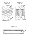
- a cutaway view of the intermediate shield is shown in Figure 2.
- the intermediate shield can be fabricated with mesh of the type shown in the cutaway view of Figure 3.
- parallel wires 27, preferably copper, are bonded between two reflective sheets 29 of foil.
- the wires all extend in one direction and when the shield surrounds the helium vessel the wires are situated so that they extend in a longitudinal direction.
- the intermediate shield 21 is secured under tension using clamps 31 around end rings 33.
- the end rings 33 are supported by isolated packets of powdered insulation 35 in contact with the helium vessel and under compression.
- the end rings which are fabricated from a relatively stiff nonmagnetic material, such as stainless steel or aluminum, have an axially ledge extending from the ring periphery towards the helium vessel.
- the isolated packets are positioned so that in addition to spacing the shield from the end of the helium vessel they also support the weight of the end rings, with the end plate ledges resting on the insulation packet axial extensions which extend over the helium vessel.
- the isolated packets comprise insulating material of compacted structure and of low thermal conductivity such as particles formed of fine silica powder.
- the packets are enclosed in a low conductivity porous membrane.
- the cryostat is evacuated prior to cooling and the porous membrane allows air to escape from the insulation packets.
- the intermediate shield is joined together over the end rings and is placed under tension. Tensioning prevents the unsupported portions of the shield from contacting the helium vessel and from sagging and contacting the nitrogen vessel.
- a conductivity of approximately 20 ⁇ W/cm-K with compressive loadings of 10-50 psi were assumed.
- FIG. 4 Another embodiment of the present invention is shown in Figure 4.
- a helium vessel 13 is wrapped with multilayer insulation 37.
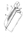
- Multilayer insulation can be applied as shown in Figure 5, by spirally wrapping insulation having a width greater than 1 inch, to avoid problems of anisotropic conductivity between adjacent reflective layers.
- the insulating material is dispensed from a spool 19 transferred from carrier to carrier to wrap the annular vessel 13.
- the multilayer insulation can be applied as shown in Figure 6, by using short strips of multilayer insulation wrapped around the vessel and stitched or bonded together.
- Three discrete layers of a multilayer insulation are shown in Figure 6. Either method allows the vessel to remain stationary during wrapping, although support of the helium vessel must be transferred back and forth between tie rod lugs to allow wrapping mechanism passage.
- the multilayer insulation 37 in Fig. 4 provides support for shield 41. Since the support is continuous, the shield only needs to be thick enough to conduct heat to the cryostat penetration 19 where it will be gas or refrigerator cooled. Typically, only a few watts need to be transferred, and the maximum distance of transfer is about 2 meters. An extremely conservative estimate (room temperature copper conductivity and the full 2 meter conduction path for the entire 2 watts transfer and 1K temperature drop) requires a shield of less than 250 pounds. Since the shield typically operates at temperatures between 20 and 400°K, copper conductivities 2 or 3 times higher should be easily achieved, reducing shield weight to less than 100 lbs. If the weight of this shield is distributed over the top third of the helium vessel, the average compressive loading on the multilayer insulation would only be 0.02 psi.
- the shield 41 must still be stiff enough that it does not sag against the nitrogen shield on the bottom sides of the helium vessel.
- multilayer insulation 43 is wrapped around the shield to act as a spacer between the intermediate radiation shield 41 and the nitrogen shield (not shown).
- a shield design which promotes easy construction when surrounded by multilayer insulation comprises a fine wire mesh of copper wire as shown in Fig. 4.
- the wire mesh can be formed around corners and clamped together at the ends of the cylindrical vessel using clamps 45.
- the mesh presents a heat sink to the adjacent foil layers of the multilayer insulation at sufficiently close intervals to keep them nearly isothermal at the shield temperature.
- a mesh bonded to foil layers as shown in Figure 2 would also act effectively in this capacity, with the circumferential wires in the mesh used to provide uniform spacing of the axial heat conducting wires being replaced by foil, yielding an even simpler structure than the mesh.
- an alternative way to provide a shield 49 that is still enough so that it does not sag against the nitrogen shield is to tension the shield around the multilayer insulation 37 using clamps 31.
- relatively stiff end rings 33 of non magnetic material such as stainless steel or aluminum are positioned at the ends of the helium vessel.
- the rings have an axially extending ledge extending from the ring periphery over the multilayer insulation to support the end rings.
- Shield 49 comprises parallel longitudinally extending copper wires bonded to a foil sheet 51. Multilayer insulation is not used between the shield 49 and the nitrogen vessel (not shown) since the foil sheet 51 serves as a radiation shield.
- foil sheets used with the wire mesh in Figures 1, 4 and 6 do not have to have appreciable structural strength they can be chosen for minimum emissivity.
- a reduction in emissivity from 0.05 to 0.03, for example, can result in a 10% reduction in helium boil off.
- the foil layers of the multilayer insulation provides radiation shielding.
- radiation shielding between the shield and the helium vessel is provided by the multilayer insulation and radiation shielding from the nitrogen vessel to the intermediate shield is provided by the foil layer of the shield.
Landscapes
- Physics & Mathematics (AREA)
- Engineering & Computer Science (AREA)
- Thermal Sciences (AREA)
- Mechanical Engineering (AREA)
- General Engineering & Computer Science (AREA)
- Electromagnetism (AREA)
- Condensed Matter Physics & Semiconductors (AREA)
- General Physics & Mathematics (AREA)
- Containers, Films, And Cooling For Superconductive Devices (AREA)
- Shielding Devices Or Components To Electric Or Magnetic Fields (AREA)
- Magnetic Resonance Imaging Apparatus (AREA)
Applications Claiming Priority (2)
| Application Number | Priority Date | Filing Date | Title |
|---|---|---|---|
| US06/816,086 US4694663A (en) | 1986-01-03 | 1986-01-03 | Low cost intermediate radiation shield for a magnet cryostat |
| US816086 | 1997-03-13 |
Publications (2)
| Publication Number | Publication Date |
|---|---|
| EP0228683A2 true EP0228683A2 (de) | 1987-07-15 |
| EP0228683A3 EP0228683A3 (de) | 1988-08-24 |
Family
ID=25219645
Family Applications (1)
| Application Number | Title | Priority Date | Filing Date |
|---|---|---|---|
| EP19860117782 Ceased EP0228683A3 (de) | 1986-01-03 | 1986-12-19 | Kostengünstiger, zwischenliegender Strahlenschild für ein Magnetkryostat |
Country Status (6)
| Country | Link |
|---|---|
| US (1) | US4694663A (de) |
| EP (1) | EP0228683A3 (de) |
| JP (1) | JPS62234306A (de) |
| KR (1) | KR900005027B1 (de) |
| CA (1) | CA1273561A (de) |
| IL (1) | IL81068A0 (de) |
Cited By (5)
| Publication number | Priority date | Publication date | Assignee | Title |
|---|---|---|---|---|
| WO1994003754A1 (en) * | 1992-07-30 | 1994-02-17 | Biomagnetic Technologies, Inc. | Cryogenic dewar and method of fabrication |
| EP1887374A1 (de) | 2006-08-01 | 2008-02-13 | General Electric Company | Vorrichtung zur thermalen Abschirmung gegen Niedrigwechselstromverlust und Herstellungsverfahren dafür |
| GB2484079A (en) * | 2010-09-28 | 2012-04-04 | Siemens Plc | Cylindrical stiffener for cryoshield |
| GB2487813A (en) * | 2010-09-28 | 2012-08-08 | Siemens Plc | Cylindrical support for cryoshield |
| WO2015074809A1 (en) * | 2013-11-22 | 2015-05-28 | Koninklijke Philips N.V. | Dynamic boil-off reduction with improved cryogenic vessel |
Families Citing this family (12)
| Publication number | Priority date | Publication date | Assignee | Title |
|---|---|---|---|---|
| DE3724562C1 (de) * | 1987-07-24 | 1989-01-12 | Spectrospin Ag | Kryostat und Verfahren zu seiner Montage |
| US4872322A (en) * | 1988-09-02 | 1989-10-10 | General Electric Company | Power operated contact apparatus for superconductive circuit |
| US5220302A (en) * | 1990-01-22 | 1993-06-15 | The University Of Texas System Board Of Regents | Nmr clinical chemistry analyzer and method of forming a shield |
| US5367261A (en) * | 1992-07-02 | 1994-11-22 | General Electric Company | Shield for a magnetic resonance imaging coil |
| US7015616B2 (en) * | 2002-04-01 | 2006-03-21 | Honeywell International, Inc. | System and method for providing coil retention in the rotor windings of a high speed generator |
| GB0403377D0 (en) * | 2004-02-16 | 2004-03-17 | Univ Aberdeen | Liquified gas cryostat |
| GB2437964B (en) * | 2006-05-06 | 2009-03-25 | Siemens Magnet Technology Ltd | An annular enclosure provided with an arrangement of recesses or protrustions to reduce mechanical resonance |
| DE102015105804A1 (de) * | 2015-04-16 | 2016-10-20 | Netzsch-Feinmahltechnik Gmbh | Rührwerkskugelmühle |
| CN104931524A (zh) * | 2015-05-15 | 2015-09-23 | 浙江大学 | 多层绝热材料性能测试装置 |
| US10794973B2 (en) | 2016-08-15 | 2020-10-06 | Koninklijke Philips N.V. | Magnet system with thermal radiation screen |
| JP7551538B2 (ja) * | 2021-03-02 | 2024-09-17 | 株式会社東芝 | 超電導電磁石装置及び超電導電磁石装置の冷却方法 |
| JP2024034719A (ja) * | 2022-09-01 | 2024-03-13 | キヤノンメディカルシステムズ株式会社 | 静磁場磁石及び磁気共鳴イメージング装置 |
Family Cites Families (7)
| Publication number | Priority date | Publication date | Assignee | Title |
|---|---|---|---|---|
| US3416693A (en) * | 1966-12-07 | 1968-12-17 | Cryogenic Eng Co | Refrigeration shielded dewar vessel |
| US3487971A (en) * | 1968-05-01 | 1970-01-06 | Beech Aircraft Corp | Cryogenic tank supporting system |
| CA861470A (en) * | 1968-10-05 | 1971-01-19 | Gulf Oil Canada Limited | Thermal insulation and thermally insulated device |
| US4055268A (en) * | 1975-11-18 | 1977-10-25 | Union Carbide Corporation | Cryogenic storage container |
| FR2360536A1 (fr) * | 1976-08-05 | 1978-03-03 | Air Liquide | Materiau isolant a faible conductibilite thermique constitue d'une structure granulaire compactee |
| EP0122498B1 (de) * | 1983-04-15 | 1988-06-08 | Hitachi, Ltd. | Kryostat |
| US4492090A (en) * | 1983-09-19 | 1985-01-08 | General Electric Company | Cryostat for NMR magnet |
-
1986
- 1986-01-03 US US06/816,086 patent/US4694663A/en not_active Expired - Fee Related
- 1986-11-28 CA CA000524117A patent/CA1273561A/en not_active Expired - Lifetime
- 1986-12-19 EP EP19860117782 patent/EP0228683A3/de not_active Ceased
- 1986-12-22 IL IL81068A patent/IL81068A0/xx unknown
- 1986-12-26 JP JP61308981A patent/JPS62234306A/ja active Granted
- 1986-12-30 KR KR1019860011512A patent/KR900005027B1/ko not_active Expired
Cited By (13)
| Publication number | Priority date | Publication date | Assignee | Title |
|---|---|---|---|---|
| WO1994003754A1 (en) * | 1992-07-30 | 1994-02-17 | Biomagnetic Technologies, Inc. | Cryogenic dewar and method of fabrication |
| US5346570A (en) * | 1992-07-30 | 1994-09-13 | Biomagnetic Technologies, Inc. | Cryogenic dewar and method of fabrication |
| CN101127270B (zh) * | 2006-08-01 | 2012-04-25 | 通用电气公司 | 用于低交流损耗热屏蔽的设备和其制造方法 |
| US7852079B2 (en) | 2006-08-01 | 2010-12-14 | General Electric Company | Apparatus for low AC loss thermal shielding and method of making same |
| EP1887374A1 (de) | 2006-08-01 | 2008-02-13 | General Electric Company | Vorrichtung zur thermalen Abschirmung gegen Niedrigwechselstromverlust und Herstellungsverfahren dafür |
| GB2484079A (en) * | 2010-09-28 | 2012-04-04 | Siemens Plc | Cylindrical stiffener for cryoshield |
| CN102420038A (zh) * | 2010-09-28 | 2012-04-18 | 英国西门子公司 | 管状低温冷却超导磁体的中空圆筒形热屏蔽 |
| GB2487813A (en) * | 2010-09-28 | 2012-08-08 | Siemens Plc | Cylindrical support for cryoshield |
| US8319588B2 (en) | 2010-09-28 | 2012-11-27 | Siemens Plc | Hollow cylindrical thermal shield for a tubular cryogenically cooled superconducting magnet |
| GB2484079B (en) * | 2010-09-28 | 2013-02-27 | Siemens Plc | A hollow cylindrical thermal shield for a tubular cryogenically cooled superconducting magnet |
| GB2487813B (en) * | 2010-09-28 | 2013-02-27 | Siemens Plc | A hollow cylindrical thermal shield for a tubular cryogenically cooled superconducting magnet |
| CN102420038B (zh) * | 2010-09-28 | 2016-08-03 | 英国西门子公司 | 管状低温冷却超导磁体的中空圆筒形热屏蔽 |
| WO2015074809A1 (en) * | 2013-11-22 | 2015-05-28 | Koninklijke Philips N.V. | Dynamic boil-off reduction with improved cryogenic vessel |
Also Published As
| Publication number | Publication date |
|---|---|
| IL81068A0 (en) | 1987-03-31 |
| JPS62234306A (ja) | 1987-10-14 |
| US4694663A (en) | 1987-09-22 |
| JPH0335803B2 (de) | 1991-05-29 |
| CA1273561A (en) | 1990-09-04 |
| KR870007395A (ko) | 1987-08-19 |
| EP0228683A3 (de) | 1988-08-24 |
| KR900005027B1 (ko) | 1990-07-18 |
Similar Documents
| Publication | Publication Date | Title |
|---|---|---|
| US4694663A (en) | Low cost intermediate radiation shield for a magnet cryostat | |
| JP3590150B2 (ja) | セラミック超伝導リード線アセンブリ | |
| EP0350262B1 (de) | Stützvorrichtung einer Strahlungsabschirmung in einem Magnetresonanz-Magneten | |
| JP5219420B2 (ja) | 外部真空容器内に支持された極低温容器を有するクライオスタット | |
| US8228147B2 (en) | Supported superconducting magnet | |
| US4492090A (en) | Cryostat for NMR magnet | |
| US4516405A (en) | Supporting tie configuration for cryostat for cold shipment of NMR magnet | |
| US7053740B1 (en) | Low field loss cold mass structure for superconducting magnets | |
| US3604832A (en) | Coaxial arrangement of tubular members, and spacer structure for such arrangements | |
| CA1241591A (en) | Foam filled insert for horizontal cryostat penetrations | |
| US5651256A (en) | Superconductive magnet having a thermal shield | |
| CA1241592A (en) | Horizontal cryostat penetration insert and assembly | |
| JPH0286105A (ja) | 円筒形極低温容器用のケーブル懸架装置 | |
| US4819450A (en) | Low cost intermediate radiation shield for a magnet cryostat | |
| US5385026A (en) | Apparatus for supporting a cryogenic fluid containment system within an enclosure | |
| US5224832A (en) | Method of fabricating a multilayer insulation blanket | |
| US6147579A (en) | Superconducting magnet non-uniform thermal insulation blankets | |
| US5571606A (en) | Ceramic superconducting lead resistant to breakage | |
| US5143770A (en) | Multilayer insulation blanket, fabricating apparatus and method | |
| EP2734856B1 (de) | Heliumdampf-magnetresonanzmagnet | |
| JPH0272605A (ja) | クエンチ保護超導電磁石コイル | |
| US4745313A (en) | Stator having three-phase superconducting windings | |
| US4622824A (en) | Cryostat suspension system | |
| EP1718897B1 (de) | Flüssiggaskryostat | |
| RU2042875C1 (ru) | Криогенный трубопровод |
Legal Events
| Date | Code | Title | Description |
|---|---|---|---|
| PUAI | Public reference made under article 153(3) epc to a published international application that has entered the european phase |
Free format text: ORIGINAL CODE: 0009012 |
|
| AK | Designated contracting states |
Kind code of ref document: A2 Designated state(s): CH DE FR GB IT LI NL |
|
| PUAL | Search report despatched |
Free format text: ORIGINAL CODE: 0009013 |
|
| AK | Designated contracting states |
Kind code of ref document: A3 Designated state(s): CH DE FR GB IT LI NL |
|
| 17P | Request for examination filed |
Effective date: 19890120 |
|
| 17Q | First examination report despatched |
Effective date: 19890810 |
|
| STAA | Information on the status of an ep patent application or granted ep patent |
Free format text: STATUS: THE APPLICATION HAS BEEN REFUSED |
|
| 18R | Application refused |
Effective date: 19910604 |
|
| RIN1 | Information on inventor provided before grant (corrected) |
Inventor name: MILLER, RUSSELL SCOTT |