EP0228551A2 - Vorschubvorrichtung für Werkstücke - Google Patents
Vorschubvorrichtung für Werkstücke Download PDFInfo
- Publication number
- EP0228551A2 EP0228551A2 EP86115958A EP86115958A EP0228551A2 EP 0228551 A2 EP0228551 A2 EP 0228551A2 EP 86115958 A EP86115958 A EP 86115958A EP 86115958 A EP86115958 A EP 86115958A EP 0228551 A2 EP0228551 A2 EP 0228551A2
- Authority
- EP
- European Patent Office
- Prior art keywords
- carriage
- cam track
- workpiece
- gripping
- cable
- Prior art date
- Legal status (The legal status is an assumption and is not a legal conclusion. Google has not performed a legal analysis and makes no representation as to the accuracy of the status listed.)
- Granted
Links
Images
Classifications
-
- B—PERFORMING OPERATIONS; TRANSPORTING
- B23—MACHINE TOOLS; METAL-WORKING NOT OTHERWISE PROVIDED FOR
- B23Q—DETAILS, COMPONENTS, OR ACCESSORIES FOR MACHINE TOOLS, e.g. ARRANGEMENTS FOR COPYING OR CONTROLLING; MACHINE TOOLS IN GENERAL CHARACTERISED BY THE CONSTRUCTION OF PARTICULAR DETAILS OR COMPONENTS; COMBINATIONS OR ASSOCIATIONS OF METAL-WORKING MACHINES, NOT DIRECTED TO A PARTICULAR RESULT
- B23Q7/00—Arrangements for handling work specially combined with or arranged in, or specially adapted for use in connection with, machine tools, e.g. for conveying, loading, positioning, discharging, sorting
- B23Q7/04—Arrangements for handling work specially combined with or arranged in, or specially adapted for use in connection with, machine tools, e.g. for conveying, loading, positioning, discharging, sorting by means of grippers
- B23Q7/041—Arrangements for handling work specially combined with or arranged in, or specially adapted for use in connection with, machine tools, e.g. for conveying, loading, positioning, discharging, sorting by means of grippers step by step
- B23Q7/042—Arrangements for handling work specially combined with or arranged in, or specially adapted for use in connection with, machine tools, e.g. for conveying, loading, positioning, discharging, sorting by means of grippers step by step for the axial transport of long workpieces
Definitions
- This invention relates to apparatus for advancing a workpiece in a processing path.
- an advancing apparatus could be provided for securely gripping the workpiece with sufficient force to prevent the workpiece from being moved out of position during processing of the workpiece. Also, it would be advantageous if, after the first workpiece has been processed, the first workpiece could be released and then a new workpiece automatically engaged by the apparatus for subsequent advancement.
- An apparatus for gripping and advancing a workpiece for processing.
- the apparatus includes a flexible tension member and a guide means for supporting the tension member.
- the tension member is entrained about the guide means for movement on the guide means in a workpiece advancing direction and in a direction opposite thereto.
- a gripping means is provided for gripping the workpiece, and the gripping means is operably connected to the tension member for operation between an open position and a closed position.
- a tensioning means is provided for selectively tensioning and untensioning the tension member for operating the gripping means from between one of the open and closed positions and the other of the positions.
- a drive means is provided for selectively moving the tension member on the guide means to move the gripping means selectively in the advancing and opposite directions.
- the apparatus of this invention is described in the normal (upright) operating position, and terms such as upper, lower, horizontal, etc., are used with reference to this position. It will be understood, however, that the apparatus of this invention may be manufactured, stored, transported, used, and sold in an orientation other than the position described.
- the apparatus of this invention has certain conventional components and control mechanisms the details of which, although not fully illustrated or described, will be apparent to those having skill in the art and an understanding of the necessary functions of such components and mechanisms.
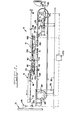
- the apparatus is designated generally by reference numeral 10 and is shown installed adjacent a workpiece processing machine 12.
- the machine 12 may be a shearing machine, punch press, cutting machine, drilling machine or the like. A number of such machines may be located generally along a processing line for operating on a workpiece seriatim or simultaneously.
- a workpiece 14 is shown engaged by the apparatus 10 in Figure l.
- the workpiece 14 is shown as a structural steel angle.
- the angle 14 is disposed in an upwardly open orientation with the angle vertex line lying in a horizontal plane and defining a passline 16 (Figure 1) along which the lowest portion of the workpiece 14 moves.
- the workpiece 14 is disposed on rollers 18 which function as support means for supporting the workpiece 14 for movement in an advancing direction toward the processing machine 12 (toward the left as viewed in Figure 1) and in an opposite direction (toward the right as viewed in Figure 1).
- the apparatus 10 includes a flexible tension member, such as a cable 20.
- the cable 20 is entrained about a guide means, such as a power-driven pulley 24 and an idler pulley 26.
- the driven pulley 24 is provided with a drive means, such as an electric motor or drive assembly 28 that includes a motor and an associated gear drive.
- a drive means such as an electric motor or drive assembly 28 that includes a motor and an associated gear drive.
- the driven pulley 24, along with the motor or drive assembly 28, are suitably supported at a predetermined elevation above the floor 30 by an appropriate frame or support member 32.
- the idler pulley 26 is mounted for rotation at a fixed height above the floor 30 to a sleeve assembly 34 which is slidably disposed on a rod 36 that is supported at one end by a frame 38 and at the other end by a floor-mounted support member 40.
- a tensioning means such as a pneumatically operated piston-cylinder actuator 42, is also mounted to the support member 40.
- the actuator 42 has a piston rod assembly 44 connected to the sleeve assembly 34. Pressurization of the cylinder of the actuator 42 causes the piston rod assembly 44 to displace the sleeve assembly 34, along with the idler pulley 26 carried thereon, away from the driven pulley 24 (to the right as viewed in Figure 1).
- a gripping means or gripping assembly 50 is provided for gripping the workpiece 14 and is secured to both ends of the cable 20.
- a gripping assembly support means is provided for supporting the gripping assembly 50 for movement in the advancing direction (to the left as viewed in Figure 1) and in the opposite direction, and the support means includes a fixed support rod 60 and a fixed support plate 62 ( Figure 6).
- Operation of the actuator 42 as described in more detail hereinafter, is effective to selectively apply tension to, and permit release of tension from, the cable 20 for operating the gripping means to grip or release the workpiece 14.
- operation of the drive assembly 28, as described in more detail hereinafter is effective to move the entire gripping assembly 50 selectively in the advancing direction and in the opposite direction.
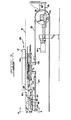
- the gripping assembly 50 includes a carriage 70, and the carriage 70 includes a rigidly connected, downwardly depending member 71 which is secured to one end of the cable 20.
- a lower jaw 72 and an upper jaw 74 are provided at the front end (left-hand end) of the carriage 70.
- the jaws 72 and 74 although not mounted directly to the carriage 70, are nevertheless ultimately carried on the carriage 70 by means of intervening members which are next described in detail.
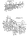
- the gripping assembly 50 further includes two spaced-apart cam track members 76 on either side of the carriage 70.
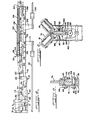
- Each cam track member 76 includes a cam track 78 which can be regarded as comprising four connected cam tracks: a horizontal front cam track 80, an inclined first cam track 82, and inclined second cam track 84, and a horizontal rear cam track 86.
- Each cam track member 76 is disposed in a carrier plate 90, and each carrier plate 90 has upper and lower retaining flanges 92 for retaining the associated cam track member 76 in a fixed vertical relationship relative to the carrier plate 90.
- Each carrier plate 90 defines a first vertical slot 94 and a second vertical slot 96. Further, each carrier plate 90 includes a vertical channel 98 for receiving a guide member 100 which is fixed to the distal end of the carriage 70. The engagement between the guide member 100 and the carrier plate channels 98 accommodates vertical movement of the carrier plates 90 relative to the carriage 70 by mechanisms described in detail hereinafter.
- the lower jaw 72 is secured in fixed relationship between the two carrier plates 90.
- the upper jaw 74 is disposed adjacent the fixed lower jaw 72 and is adapted to slide vertically upwardly and downwardly relative to both the lower jaw 72 and the carrier plates 90.
- the upper jaw 74 defines an aperture 102 which is in registry with the first vertical slots 94 of the carrier plates 90.
- a bolt 104 is mounted through the upper jaw aperture 102 and extends through the carier plate vertical slots 94 and also through the cam track 78 in each of the cam track members 76.
- the bolt 104 is retained within the assembly by means of a nut 106.
- the bolt 104 functions as a cam follower within the cam track 78 for engaging the front cam track 80 and inclined first cam track 82. As explained in more detail hereinafter, this effects opening and closing of the upper jaw 74.
- the carriage 70 defines an aperture 108 which is in registry with each second vertical slot 96 of each carrier plate 90.
- a bolt 112 is disposed within the aperture 108 and extends through the second vertical slot 96 in each carrier plate 90 and through the cam track 78 in each cam track member 76.
- the bolt 112 is retained in the assembly my means of a nut 114.
- the bolt 112 functions as a second cam follower for engaging the inclined second cam track 84 and the rear cam track 86. As explained in detail hereinafter, this accommodates longitudinal movement of the cam track members 76 with the consequent vertical displacement of the cam track members 76, carrier plates 90, and jaws 72 and 74 together relative to the carriage 70.
- Each link 120 defines an aperture 122 which is in registry with apertures 124 defined in the adjacent cam track members 76.
- Each link 120 is pivotally connected to the adjacent cam track member 76 through the apertures 122 and 124 by means of a suitable pin or bolt 126 which may be secured with a thin nut 128.
- each link 120 is pivotally connected at its rear end to an actuator link assembly 130 by means of a suitable connecting pin assembly 132.
- the actuator link assembly 130 is slidably carried on the carriage 70 and includes two spaced-apart parallel plates 134 with depending plates 136 to which one end of the cable 20 is attached.
- the carriage 70 defines a horizontal slot 140.
- a pin 142 is mounted between the two spaced-apart plates 136 and is received within the carriage slot 140. The pin 142, in engagement with the slot 140, retains the actuator link assembly 130 in position on the carriage 70 and prevents the actuator link assembly 130 from falling out of the illustrated orientation on the carriage 70.
- the carriage 70 also defines another horizontal slot 146 between the links 120.
- a pin 148 is disposed within the carriage slot 146 and is connected on each end to one of the links 120.
- the pin 148 has a diameter somewhat smaller than the height of the slot 146.
- the clearance between the pin 148 and slot 146 is sufficient to accommodate pivoting movement of the links 120 between a generally horizontal position (illustrated in Figures 1 and 2) and an angled position (illustrated in Figures 3 and 4).
- the pin 148 functions to engage the upper horizontal surface of the carriage slot 146 to prevent the links 120 and actuator link assembly 130 from lifting upwardly away from the carriage 70.
- the carriage 70 has at its rearward end a bracket 150 defining an aperture (not visible in the Figures) for slidably receiving therein a rod 152.
- the rod 152 extends along the top of the carriage 70 and is secured at its forward end to a socket 154 which is disposed between the actuator link assembly plates 134 and which is pivotally connected to the pin assembly 132.
- the spring 156 acts at its rearward end against the carriage bracket 150 and at the forward end against the socket 154.
- the entire gripping assembly 50 is supported from the carriage 70 in a generally horizontal orientation at a selected height above the floor 30 by means of the previously described support rod 60 and support plate 62 ( Figure 6).
- two brackets 158 are provided on one side of the carriage 70 for slidably engaging the support rod 60.
- two rollers 160 are mounted for engaging the support plate 62.
- the support rod 60 and support plate 62 are mounted to suitable frame members 162 which project, at spaced-apart intervals, alongside the carriage 70 and to which are mounted the workpiece support rollers 18.
- the drive assembly 28 includes a direct current electric servomotor or an alternating current electric servomotor. As schematically illustrated in Figure 1, the drive assembly 28 is provided with a suitable conventional controller 170.
- the controller 170 receives input from a suitable conventional rotational feedback device 172 associated with the idler pulley 26.
- the rotational feedback device may be an encoder or resolver, and it senses the rotation of the idler pulley 26 and transmits a signal, as a function of such rotation, to the controller 170.
- the contoller 170 also receives input from a suitable conventional workpiece position sensing device, such as a photocell 174 mounted below the workpiece passline 16 in alignment with a conventional associated light source 176 that is mounted above the workpiece passline by an amount sufficient to permit passage of the workpiece 14.
- a suitable conventional workpiece position sensing device such as a photocell 174 mounted below the workpiece passline 16 in alignment with a conventional associated light source 176 that is mounted above the workpiece passline by an amount sufficient to permit passage of the workpiece 14.
- a suitable position indicating device such as an appropriate conventional limit switch 178, is provided at the rear end of the apparatus 10 at a predetermined point along the path of movement of the gripping assembly 50.
- the controller 170 receives input from the limit switch 178.
- the bolt 104 is at the top of the inclined first cam track 82 which has the effect of maintaining the upper jaw 74, which is mounted to the bolt 104, in the elevated position relative to the fixed lower jaw 72. It is to be noted that the elevated position of the upper jaw 74 and of the bolt 104 is accommodated in each of the carrier plates 90 by the first vertical slot 94 ( Figure 8).
- Clamping of the workpiece 14 between the jaws 72 and 74 is initiated by pressurizing the pneumatically operated piston-cylinder actuator 42. This moves the idler pulley 26 away from the cylinder of the actuator 42 and away from the power-driven pulley 24. As the idler pulley 26 is moved to the extended position, the ends of the cable 20 secured to the carriage member 71 and actuator link assembly plates 136 tend to be pulled apart and effect compression of spring 156.
- the idler pulley rotation feedback device 172 senses the initiation of the rotation of the idler pulley 26.
- the controller 170 upon receiving the rotation sensing input from the feedback device 172, energizes the servomotor drive assembly 28 to rotate the power-driven pulley 24 in the counterclockwise direction as viewed in Figures 1 and 2.
- the amount of rotation of the power-driven pulley 24 is just sufficient to pull as much cable 20 as needed in the counterclockwise direction so as to prevent significant rotation of the idler pulley 26 as the idler pulley 26 moves away from the power-driven pulley 24 to its extended position.
- the bolt 104 on which the upper jaw 74 is mounted moves with the upper jaw 74 in carriage 70 to the left relative to the cam track members 76.
- the bolt 104 thus necessarily functions as a cam follower engaged with the inclined first cam track 82 and causes the upper jaw 74 to move down toward the lower jaw 72 so as to grip the workpiece 14 as illustrated in Figure 1.
- Figure 1 illustrates the positions of the bolts 104 and 112 in the cam tracks 82 and 86, respectively, in the clamping mode.
- the actuator 42 continues to exert a displacement force on the idler pulley 26 to increase tension on the cable 20.
- the maximum cable tension is determined by the maximum pressurization force that the actuator 42 is capable of generating. This maximum tension force on the cable 20 is necessarily transferred through the components of the gripping assembly 50 in the manner described above, and this results in the application of a maximum gripping force.
- a suitable sensor (not illustrated) may be provided in the pneumatic actuator 42 for determining the maximum pressurization at which point the next step in the operating cycle is initiated. Alternatively, the next step in the operating cycle may be initiated in response to a suitable predetermined time delay.
- the rotation sensor feedback device 172 can be operated in a different mode so as to permit rotation of the pulley 26 in response to the operation of the motor drive assembly 28.
- the controller 170 ( Figure 1) operates the motor drive assembly 28 to continuously rotate the power-driven pulley 24 in the counterclockwise direction as viewed in Figure 1 so as to rotate the cable 20 in the counterclockwise direction and pull the entire carriage 70 to the left toward the workpiece processing machine 12. Because of the high tension in the cable 20, the friction force between the cable 20 and the pulleys 24 and 26 is very high. Thus, the power-driven pulley 24 causes movement of the cable on the pulleys with substantially no slippage.
- the leading edge of the workpiece 14 interrupts the circuit of the photocell 174 ( Figure 1). This is input to the controller 170 which initiates a length sensing mode of operation.
- the motor drive assembly 28 is operated for a predetermined number of revolutions or for a predetermined period of time by a suitable conventional control sub-system to advance a predetermined length of the workpiece 14 into the workpiece processing machine 12.
- the device 172 operates to accurately determine the cable movement. This can compensate for cumulative error.
- the rotation of the motor drive assembly 28 is terminated by the controller 170.
- the workpiece processing machine 12 is then operated as desired to effect a particular processing of the workpiece 14 at that position (e.g., drilling, shearing, etc.). If desired, the controller 170 can initiate subsequent advancements of the workpiece 14 through predetermined distances for subsequent operations on the workpiece 14 by the workpiece processing machine 12 or by other, downstream, workpiece processing machines.
- the pneumatic actuator 42 is depressurized by the operator to permit the idler pulley 26 to be returned or retracted from the extended position. Movement of the idler pulley 26 from the extended to the retracted position is effected by the spring 156 as the actuator 42 is depressurized.
- the spring 156 effects relative movement between the gripping assembly components so as to effect relative displacement between the carriage 71 and the plates 136 so that the distance between them is decreased. This reduces the distance between the ends of the cable 20.
- the idler pulley rotation feedback device 172 senses the initiation of the rotation of the idler pulley 26.
- the controller 170 upon receiving the rotation sensing input from the feedback device 172, energizes the servomotor drive assembly 28 to rotate the power-driven pulley 24 in the clockwise direction as viewed in the Figures 1 and 3.
- the amount of rotation of the power-driven pulley 24 is just sufficient to pull as much cable 20 as needed in the clockwise direction so as to prevent significant rotation of the idler pulley 26 as the idler pulley 26 moves toward the power-driven pulley 24 to the retracted position. Since the power-driven pulley 24 is being rotated to pull the bottom run of the cable 20 from the inwardly moving idler pulley 26, the end of the cable 20 attached to the carriage at member 71 is necessarily pulled away from the power-driven pulley 24. However, the spring 156 prevents movement of the plates 136 and the connected cable end. The plates 136 and connected cable end remain in the same position relative to both the carriage 70 and the power driven pulley 24. The spring 156 acts against the carriage rear bracket 150 to push the carriage 70 rearwardly a small amount (to the right as viewed in Figures 1 and 3).
- the bolt 104 on which the upper jaw 74 is mounted also moves with the upper jaw 74 in carriage 70 to the right relative to the cam track members 76.
- the bolt 104 thus necessarily functions as a cam follower engaged with the inclined first cam track 82 and causes the upper jaw 74 to move up away from the lower jaw 72 to the open position.
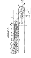
- the cam follower bolt 104 is at the top of the inclined first cam track ( Figure 2 illustrates the bolt 104 in such a position).
- the gripping assembly jaws are again closed, and the whole gripping assembly 50 is lowered below the passline 16 as illustrated in Figures 3 and 4.
- the actuator 42 is pressurized to again displace the idler pulley 26 outwardly away from the power-driven pulley 24 toward the extended position.
- the idler pulley 26 is moved to the extended position, the ends of the cable 20 secured to the carriage member 71 and actuator link assembly plates 136 tend to be pulled apart and effect compression of spring 156.
- the idler pulley rotation feedback device 172 senses the initiation of the rotation of the idler pulley 26.
- the controller 170 upon receiving the rotation sensing input from the feedback device 172, energizes the servomotor drive assembly 28 to rotate the power-driven pulley 24 in the counterclockwise direction as viewed in Figures 1 and 3.
- the amount of rotation of the power-driven pulley 24 is just sufficient to pull as much cable 20 as needed in the counterclockwise direction so as to prevent significant rotation of the idler pulley 26 as the idler pulley 26 moves away from the power-driven pulley 24 to its extended position. Since the power-driven pulley 24 is being rotated to feed the bottom run of the cable 20 toward the outwardly moving idler pulley 26, the end of the cable 20 attached to the carriage at member 71 is necessarily pulled toward the power-driven pulley 24 while the cable end attached to the carriage plates 136 remains stationary. This results in the carriage 70 (with the jaws 72 and 74) being pulled forward some amount (relative to the other end of the cable 20 attached to the plates 136). The empty jaws 72 and 74 are thus carried a small distance further toward the workpiece processing machine 12 (toward the left as illustrated in Figure 3).
- the tension force continues to be transmitted from the actuator link assembly 130 through the links 120 to the cam track members 76. This is opposite to the direction of the tension force applied to the carriage 70 through member 71 as the carriage 70 moves to the left.
- the bolt 104 on which the upper jaw 74 is mounted and which is necessarily maintained by the gripping assembly 50 in fixed longitudinal relationship on the carriage 70, moves with the upper jaw 74 in carriage 70 to the left relative to the cam track members 76.
- the bolt 104 thus necessarily again functions as a cam follower engaged with the inclined first cam track 82 and causes the upper jaw 74 to move down toward the lower jaw 72.
- the upper jaw 74 continues to be lowered all the way until it abuts the lower jaw 72. As this occurs, relative movement of the gripping assembly components results in the inclined first cam track 82 of each cam track member forcing the upper jaw cam follower bolt 104 downwardly. Continued relative longitudinal movement between the carriage 70 and the actuator link assembly 130 results in the upper jaw cam follower bolt 104 being positioned at the front end of the front cam track 80.
- cam follower bolt 112 is carried forward out of the cam tracks 86 and ultimately becomes positioned at the top of the inclined second cam track 84 of each cam track member 76. Since the cam follower bolt 112 is fixed in the end of the carriage 70, engagement of the cam follower bolt 112 with the inclined second cam track 84 necessarily results in the cam track members 76 being lowered relative to the cam follower bolt 112 and to the carriage 70.
- the controller 170 is programmed to disregard the input of the rotation sensor 172 during this gripping assembly return step. At this point, the motor is energized to effect rotation of the power-driven pulley 24 in the appropriate direction of rotation (clockwise as viewed in Figure 1). This causes the tensioned cable 20 to rotate with the pulley 24 so as to pull the entire carriage 70 back to the initial longitudinal position (behind the new workpiece 14', but still below the passline 16). This is sensed by the limit switch 178 which is actuated when the carriage 70 reaches this position and which, through input to the controller 170 ( Figure 1), deenergizes the drive assembly motor.
- the program for the controller 170 permits the controller 170 to again respond to the rotation sensor input 172. Also, in response to the actuation of limit switch 178, the actuator 42 is depressurized to release the displacement force on the idler pulley 26. This permits the spring 156 to effect relative displacement between the gripping assembly components so as to effect relative displacement between the carriage member 71 and plates 136 so that the distance between them is decreased. This reduces the distance between the ends of the cable 20.
- the idler pulley rotation feedback device 172 senses the initiation of the rotation of the idler pulley 26.
- the controller 170 upon receiving the rotation sensing input from the feedback device 172, energizes the servomotor drive assembly 28 to rotate the power-driven pulley 24 in the clockwise direction as viewed in Figures 1 and 3.
- the amount of rotation of the power-driven pulley 24 is just sufficient to pull as much cable 20 as needed in the clockwise direction so as to prevent significant rotation of the idler pulley 26 as it moves toward the power-driven pulley 24 to the retracted position. Since the power-driven pulley 24 is being rotated to pull the bottom run of the cable 20 from the inwardly moving idler pulley 26, the end of the cable 20 attached to the carriage at member 71 is necessarily pulled away from the power-driven pulley 24. However, the spring 156 prevents movement of the plates 136 and the connected cable end. The plates 136 and connected cable end remain stationary and at the same distance from the power-driven pulley 24. The spring 156 acts against the carriage rear bracket 150 to push the carriage 70 rearwardly a small amount (to the right as viewed in Figures 1 and 3).
- the bolt 104 on which the upper jaw 74 is mounted moves with the upper jaw 74 in carriage 70 to the right relative to the cam track members 76.
- the bolt 104 thus necessarily functions as a cam follower engaged with the inclined first cam track 82 and causes the upper jaw 74 to move up away from the lower jaw 72 to the open position.
- the cam follower bolt 104 is at the top of the inclined first cam track ( Figure 2 illustrates the bolt 104 in such a position).
- the cam follower bolt l12 also assumes a new position. Specifically, the position of the bolt 112 at the top of the inclined second cam track 84 ( Figure 4) changes so that the bolt 112 is at the rear end of the rear cam track 86. This action causes the cam track members 76 to be elevated relative to the carriage 70, thereby raising the entire assembly of the gripping jaws 72 and 74 toward the passline 16.
- the gripping assembly 50 can then be moved forward to engage the rear end of the new workpiece 14'.
- the program of the controller 170 disregards the input from the rotation sensor 172 when a limit switch or other suitable sensor (not illustrated) signals the controller 170 ( Figure 1) that the jaws are opened and are ready to be moved forward.
- the controller 170 then energizes the motor drive assembly 28 to rotate the power-driven pulley 24 in the counterclockwise direction (as viewed in Figure 1). This pulls the cable 20 in the counterclockwise direction of rotation around the pulleys and moves the carriage 70 to bring the open jaws into position against the rear end of the new workpiece 14'.
- the spring 156 exerts a sufficient low tension force on the cable 20 so that the cable 20 is properly driven by the pulley 24.
- the motor drive assembly 28 is deenergized in response to visual observation by the operator or in response to the jaws engaging a limit switch or other suitable sensor (not illustrated) at the rear end position of the workpiece 14'.
- the program of the controller 170 again permits the controller to respond to subsequent input from the rotation sensor 172.
- the flexible tension member or cable 20 need not necessarily be mounted on two spaced-apart pulleys as illustrated.
- a flexible tension member may be entrained around any suitable one-piece or multi-piece guide system.
- means for applying tension to the flexible tension member may take a form other than the illustrated pneumatic actuator and pulley assembly.
- a small movable guide could be provided with means for moving the guide against the flexible tension member to apply tension.
- the apparatus has been described in connection with gripping and advancing a workpiece having the shape of a structural angle member, it is to be realized that the apparatus may be adapted to accommodate workpieces having a variety of shapes. Such accommodation would typically be effected by making appropriate modifications to the shape of the gripping jaws and to the orientation of the support rollers 18.
- the apparatus of the present invention can be automatically operated with appropriate conventional controllers which can compensate for accumulative error resulting from the assembled components, such as variations in the circumferences of the pulleys.
- a conventional control system may be conveniently pre-programmed for proper positioning of the workpiece, including workpieces which may have a length of 10 meters or more.
- the described preferred embodiment of the apparatus 10 accommodates the efficient processing of workpieces by lowering the gripping jaws below the workpiece passline so that the gripping jaws can be returned to a loading position below the workpiece passline at the same time a new workpiece is conveyed above.
- simplification of the apparatus design can be achieved by eliminating certain structural features which serve only to raise and lower the jaws together relative to the workpiece passline.
- the spring 156 is a compression spring functioning to open the gripping jaws when the flexible tension member cable 20 is untensioned. It will be appreciated that the apparatus 10 could be modified to effect the opening of the gripping jaws by tensioning the cable and to effect closing of the jaws by means of a spring.
Landscapes
- Engineering & Computer Science (AREA)
- Mechanical Engineering (AREA)
- Manipulator (AREA)
Applications Claiming Priority (2)
| Application Number | Priority Date | Filing Date | Title |
|---|---|---|---|
| US812739 | 1985-12-23 | ||
| US06/812,739 US4715774A (en) | 1985-12-23 | 1985-12-23 | Workpiece advancing apparatus |
Publications (3)
| Publication Number | Publication Date |
|---|---|
| EP0228551A2 true EP0228551A2 (de) | 1987-07-15 |
| EP0228551A3 EP0228551A3 (en) | 1988-11-02 |
| EP0228551B1 EP0228551B1 (de) | 1991-04-24 |
Family
ID=25210483
Family Applications (1)
| Application Number | Title | Priority Date | Filing Date |
|---|---|---|---|
| EP86115958A Expired EP0228551B1 (de) | 1985-12-23 | 1986-11-18 | Vorschubvorrichtung für Werkstücke |
Country Status (3)
| Country | Link |
|---|---|
| US (1) | US4715774A (de) |
| EP (1) | EP0228551B1 (de) |
| DE (1) | DE3678920D1 (de) |
Cited By (5)
| Publication number | Priority date | Publication date | Assignee | Title |
|---|---|---|---|---|
| EP0348536A1 (de) * | 1988-06-25 | 1990-01-03 | BALJER & ZEMBROD GmbH & Co. | Abbundanlage zum Bearbeiten von Kantholz |
| FR2726778A1 (fr) * | 1994-11-14 | 1996-05-15 | Parveau Mab | Dispositif d'alimentation controlee d'un poste a usinages multiples notamment pour la preparation d'un profile |
| CN105555446A (zh) * | 2013-09-18 | 2016-05-04 | 西铁城控股株式会社 | 棒材供应装置及带有棒材供应装置的数控工作机械 |
| CN109335553A (zh) * | 2018-12-10 | 2019-02-15 | 深圳市深丰迪自动化科技有限公司 | 工件步进轨道及系统 |
| CN109333811A (zh) * | 2018-11-30 | 2019-02-15 | 山东豪迈机械制造有限公司 | 一种夹紧机构及张拉装置 |
Families Citing this family (6)
| Publication number | Priority date | Publication date | Assignee | Title |
|---|---|---|---|---|
| US4898044A (en) * | 1988-10-26 | 1990-02-06 | Emerson Electric Co. | Cam-driven linear actuator apparatus |
| GB8904569D0 (en) * | 1989-02-28 | 1989-04-12 | De La Rue Systems Ltd | Article handling apparatus |
| US4941564A (en) * | 1989-04-06 | 1990-07-17 | Honda Giken Kogyo Kabushiki Kaisha | Method of and apparatus for transferring motorcycle |
| DE69123279T2 (de) * | 1990-04-06 | 1997-04-24 | Canon K.K., Tokio/Tokyo | Transportvorrichtung für Substrate und Verfahren zur Kontrolle |
| US5256212A (en) * | 1992-03-27 | 1993-10-26 | Peddinghaus Corporation | Method and apparatus for flame cutting a workpiece |
| US8021086B2 (en) * | 2007-03-28 | 2011-09-20 | Controlled Automation, Incorporated | Drilling apparatus and method |
Family Cites Families (17)
| Publication number | Priority date | Publication date | Assignee | Title |
|---|---|---|---|---|
| US1693074A (en) * | 1926-12-24 | 1928-11-27 | Falco Michael | Lifting device |
| US1888659A (en) * | 1930-04-10 | 1932-11-22 | Hoe & Co R | Sheet feeding mechanism |
| US2007886A (en) * | 1933-02-06 | 1935-07-09 | Druckmaschinen Ag | Sheet feeding device for cylinder printing presses |
| US2966086A (en) * | 1955-07-02 | 1960-12-27 | Robert L Sjostrom | Fabric cutting machine |
| US3221901A (en) * | 1961-12-06 | 1965-12-07 | Numeric Systems Of Texas Inc | Automatic punch press |
| NL296527A (de) * | 1962-08-13 | |||
| US3233750A (en) * | 1963-07-05 | 1966-02-08 | Us Industries Inc | Gripping and releasing device for feed mechanisms |
| US3533619A (en) * | 1968-07-26 | 1970-10-13 | Resistance Welder Corp | Sheet feeding means for roll forming mill |
| US3792857A (en) * | 1972-08-22 | 1974-02-19 | American Screen Printing | Takeoff apparatus |
| US3976322A (en) * | 1975-10-22 | 1976-08-24 | Norman Allen Johnson | Self-aligning grapple swivel |
| US4058307A (en) * | 1975-11-03 | 1977-11-15 | American Screen Printing Equipment Company | Feed and takeoff assembly |
| US4270652A (en) * | 1977-08-17 | 1981-06-02 | Am International, Inc. | Automatic collator unloader |
| JPS55131451A (en) * | 1979-03-24 | 1980-10-13 | Murata Mach Ltd | Positioning and clamping plate material |
| JPS57132983A (en) * | 1981-02-12 | 1982-08-17 | Yoshida Kogyo Kk | Conveyor for product |
| JPS57153840A (en) * | 1981-03-09 | 1982-09-22 | Osaka Kagaku Goukin Kk | Method and device for cutting off bundled section of bag end |
| US4545609A (en) * | 1983-12-21 | 1985-10-08 | Henry Pasquazzi | Curb lifting device |
| DE3514356A1 (de) * | 1985-04-20 | 1986-10-23 | Peddinghaus, Carl Ullrich, Dr., 5600 Wuppertal | Vorrichtung fuer die zufuehrung von stabfoermigen werkstuecken zu einer bearbeitungsmaschine |
-
1985
- 1985-12-23 US US06/812,739 patent/US4715774A/en not_active Expired - Lifetime
-
1986
- 1986-11-18 EP EP86115958A patent/EP0228551B1/de not_active Expired
- 1986-11-18 DE DE8686115958T patent/DE3678920D1/de not_active Expired - Lifetime
Cited By (8)
| Publication number | Priority date | Publication date | Assignee | Title |
|---|---|---|---|---|
| EP0348536A1 (de) * | 1988-06-25 | 1990-01-03 | BALJER & ZEMBROD GmbH & Co. | Abbundanlage zum Bearbeiten von Kantholz |
| FR2726778A1 (fr) * | 1994-11-14 | 1996-05-15 | Parveau Mab | Dispositif d'alimentation controlee d'un poste a usinages multiples notamment pour la preparation d'un profile |
| CN105555446A (zh) * | 2013-09-18 | 2016-05-04 | 西铁城控股株式会社 | 棒材供应装置及带有棒材供应装置的数控工作机械 |
| US20160214179A1 (en) * | 2013-09-18 | 2016-07-28 | Citizen Machinery Co., Ltd. | Bar material supplying device and numerical control machine tool having the same |
| US9731353B2 (en) * | 2013-09-18 | 2017-08-15 | Citizen Machinery Co., Ltd. | Bar material supplying device and numerical control machine tool having the same |
| CN109333811A (zh) * | 2018-11-30 | 2019-02-15 | 山东豪迈机械制造有限公司 | 一种夹紧机构及张拉装置 |
| CN109335553A (zh) * | 2018-12-10 | 2019-02-15 | 深圳市深丰迪自动化科技有限公司 | 工件步进轨道及系统 |
| CN109335553B (zh) * | 2018-12-10 | 2024-05-24 | 深圳市深丰迪自动化科技有限公司 | 工件步进轨道及系统 |
Also Published As
| Publication number | Publication date |
|---|---|
| US4715774A (en) | 1987-12-29 |
| EP0228551B1 (de) | 1991-04-24 |
| EP0228551A3 (en) | 1988-11-02 |
| DE3678920D1 (de) | 1991-05-29 |
Similar Documents
| Publication | Publication Date | Title |
|---|---|---|
| CN106392650B (zh) | 铝模板数控锯、冲集成生产线 | |
| US4715774A (en) | Workpiece advancing apparatus | |
| US2763229A (en) | Loading and unloading apparatus | |
| US4708573A (en) | Apparatus for the handling of metal sheets | |
| EP0798072A1 (de) | Automatisches verfahren mit steigender speisung für lange werkstücke und vorrichtung dafür | |
| GB2033795A (en) | Electrical component inserting machine | |
| US5169047A (en) | Compact rivet attachment apparatus | |
| WO2018219359A1 (zh) | 一种线缆自动剥皮装置 | |
| GB2104859A (en) | Method and means for the independent delivery and removal of pallets of a pallet magazine into or out of the working space of a machine tool | |
| CN114160691A (zh) | 一种折弯中心前部送料设备 | |
| CN205733827U (zh) | 铝模板数控锯、冲集成生产线 | |
| US20040200051A1 (en) | Workpiece feeder for a cutting metal-working machine or the like | |
| US4803879A (en) | Slip lock forming apparatus | |
| US4614265A (en) | Apparatus for automatically splitting transfer feed rails in a transfer feed press | |
| US3955337A (en) | Apparatus for manufacturing and wrapping labels | |
| US4669346A (en) | Machine with work positioning carriage | |
| US4403390A (en) | Radial lead inserting machine | |
| US4126030A (en) | Retractable pressure die | |
| US3815393A (en) | N.c. automatic folding machine | |
| JP2824891B2 (ja) | 折曲機のワーク前面位置決め装置 | |
| US4540084A (en) | Device for automatically transferring printed circuit base plates from the loading to the printing zone | |
| CN108527672B (zh) | 一种珍珠自动打孔机 | |
| CN222449414U (zh) | 一种电梯导轨支架的制造设备 | |
| EP0570830A1 (de) | Stangenzuführeinrichtung mit gleitender Spannbacke | |
| US3630069A (en) | Feeder for small diameter bars |
Legal Events
| Date | Code | Title | Description |
|---|---|---|---|
| PUAI | Public reference made under article 153(3) epc to a published international application that has entered the european phase |
Free format text: ORIGINAL CODE: 0009012 |
|
| AK | Designated contracting states |
Kind code of ref document: A2 Designated state(s): DE FR IT |
|
| PUAL | Search report despatched |
Free format text: ORIGINAL CODE: 0009013 |
|
| AK | Designated contracting states |
Kind code of ref document: A3 Designated state(s): DE FR IT |
|
| 17P | Request for examination filed |
Effective date: 19881125 |
|
| 17Q | First examination report despatched |
Effective date: 19900209 |
|
| GRAA | (expected) grant |
Free format text: ORIGINAL CODE: 0009210 |
|
| AK | Designated contracting states |
Kind code of ref document: B1 Designated state(s): DE FR IT |
|
| REF | Corresponds to: |
Ref document number: 3678920 Country of ref document: DE Date of ref document: 19910529 |
|
| ET | Fr: translation filed | ||
| ITF | It: translation for a ep patent filed | ||
| PLBE | No opposition filed within time limit |
Free format text: ORIGINAL CODE: 0009261 |
|
| STAA | Information on the status of an ep patent application or granted ep patent |
Free format text: STATUS: NO OPPOSITION FILED WITHIN TIME LIMIT |
|
| 26N | No opposition filed | ||
| PGFP | Annual fee paid to national office [announced via postgrant information from national office to epo] |
Ref country code: FR Payment date: 19931110 Year of fee payment: 8 Ref country code: DE Payment date: 19931110 Year of fee payment: 8 |
|
| PG25 | Lapsed in a contracting state [announced via postgrant information from national office to epo] |
Ref country code: FR Effective date: 19950731 |
|
| PG25 | Lapsed in a contracting state [announced via postgrant information from national office to epo] |
Ref country code: DE Effective date: 19950801 |
|
| REG | Reference to a national code |
Ref country code: FR Ref legal event code: ST |
|
| PG25 | Lapsed in a contracting state [announced via postgrant information from national office to epo] |
Ref country code: IT Free format text: LAPSE BECAUSE OF NON-PAYMENT OF DUE FEES;WARNING: LAPSES OF ITALIAN PATENTS WITH EFFECTIVE DATE BEFORE 2007 MAY HAVE OCCURRED AT ANY TIME BEFORE 2007. THE CORRECT EFFECTIVE DATE MAY BE DIFFERENT FROM THE ONE RECORDED. Effective date: 20051118 |