EP0570830A1 - Stangenzuführeinrichtung mit gleitender Spannbacke - Google Patents
Stangenzuführeinrichtung mit gleitender Spannbacke Download PDFInfo
- Publication number
- EP0570830A1 EP0570830A1 EP93107732A EP93107732A EP0570830A1 EP 0570830 A1 EP0570830 A1 EP 0570830A1 EP 93107732 A EP93107732 A EP 93107732A EP 93107732 A EP93107732 A EP 93107732A EP 0570830 A1 EP0570830 A1 EP 0570830A1
- Authority
- EP
- European Patent Office
- Prior art keywords
- bar
- jaws
- pusher
- feeding
- guideways
- Prior art date
- Legal status (The legal status is an assumption and is not a legal conclusion. Google has not performed a legal analysis and makes no representation as to the accuracy of the status listed.)
- Withdrawn
Links
Images


Classifications
-
- B—PERFORMING OPERATIONS; TRANSPORTING
- B23—MACHINE TOOLS; METAL-WORKING NOT OTHERWISE PROVIDED FOR
- B23B—TURNING; BORING
- B23B13/00—Arrangements for automatically conveying or chucking or guiding stock
- B23B13/02—Arrangements for automatically conveying or chucking or guiding stock for turning-machines with a single working-spindle
-
- B—PERFORMING OPERATIONS; TRANSPORTING
- B23—MACHINE TOOLS; METAL-WORKING NOT OTHERWISE PROVIDED FOR
- B23Q—DETAILS, COMPONENTS, OR ACCESSORIES FOR MACHINE TOOLS, e.g. ARRANGEMENTS FOR COPYING OR CONTROLLING; MACHINE TOOLS IN GENERAL CHARACTERISED BY THE CONSTRUCTION OF PARTICULAR DETAILS OR COMPONENTS; COMBINATIONS OR ASSOCIATIONS OF METAL-WORKING MACHINES, NOT DIRECTED TO A PARTICULAR RESULT
- B23Q7/00—Arrangements for handling work specially combined with or arranged in, or specially adapted for use in connection with, machine tools, e.g. for conveying, loading, positioning, discharging, sorting
- B23Q7/03—Arrangements for handling work specially combined with or arranged in, or specially adapted for use in connection with, machine tools, e.g. for conveying, loading, positioning, discharging, sorting by means of endless chain conveyors
Definitions
- the present invention relates to a device for feeding bars to machine tools of the type described in the preamble of the main claim.
- Most bar guiding devices in feeders for machine tools substantially comprise tubular elements or a plurality of aligned jaws, by means of which a bar is supported to rotate with the spindle of the machine tool, and to slide forwards while it is maintained in rapid rotation; one or more pusher devices act on the bar to move it by steps towards the spindle of the machine tool.
- EP-A- 213659 and EP-A 384 344 illustrate guide devices composed of a plurality of opposite jaws in which the jaws can open to enable the bars to be loaded, and a pusher normally provided in these types of feeders, to pass through.
- the feeders for bars of the kind mentioned above suffer from numerous disadvantages caused by vibrations and noise generated by the impact of the rapidly rotating bars against the support and guide jaws; this disadvantage, which entails harmful effects on the machining of the workpieces and on the proper functioning of the machine tool, in addition to that of the feeder itself, is mainly due to the fact that there are long unsupported portions of the bar which are not adequately guided between jaws or groups of adjacent jaws, more particularly between the rear pusher and the guide jaws themselves. Moreover, unsupported portions of a bar may become slightly deformed and rotate eccentrically, causing strong impact forces which are extremely dangerous due to the high working speeds of modern machine tools. This disadvantage is particularly felt both for bars which are large in diameter, due to the considerable masses in rotation, and for bars which are small in diameter, even filiform, or of a few millimetres, which may bend or even break if not adequately supported.
- the object of the present invention is to provide a bar feeder for machine tools which is substantially free of the disadvantages found in previously known devices, enabling the elimination of long unsupported portions of the bars or those which are not adequately guided, more particularly between the pusher and the bar support jaws, and which at the same time can also be adjusted to feed bars of different diameters.
- a further object of the invention is to provide a bar feeder of the kind mentioned above, by means of which it is also possible to feed bars which are extremely small in diameter without the bars being subjected to strong axial thrusts or peak loads which could bend or break the bars themselves.
- the abovementioned objects are achieved by means of a bar feeder for machine tools having the features of the main claim.
- the substantial innovation of the present invention mainly consists in the fact that the jaws for supporting the bars and a pusher can move together along guideways parallelly arranged to the feeding direction of the bars, supporting said bars in narrowly spaced positions, accompanying them at the same time during their forward movement.
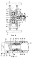
- reference 10 denotes the assembly of the feeder device.
- 11 denotes a frame, partially shown, while 12 denotes a front guide sleeve, defining the feeding axis for a bar 13 in the direction of a spindle of a machine tool, not shown.
- the feed device 10 substantially comprises two sets of jaws 14 and 15 respectively for supporting the bar 13 which has to be moved forwards by steps or continuously.
- the jaws 14, 15 are slidingly carried , with the bar 13, by respective opposite guideways 16, 17 which extend parallelly in the feeding direction of the bars 13.
- the jaws 14 and 15 in each set are connected to respective drive chains 18, 19, in the form of endless chains which wind around end gears 20A, 20B, and 21A, 21B respectively, of which the gears 20B and 21B are connected to a drive motor 22, via shafts 23, 24 and a group of gears 25.
- the jaws 14 and 15 are jointed or connected to the drive chains 18, 19 by suitable pins or with suitable connecting means allowing the jaws to rotate with the chains around the rollers or idle gears 20A and 21A positioned at one end and in the feeding direction of the bar 13, during the passage of the jaws 14 and 15 from the position inside the guideways 16 and 17, to support the bar, as shown in Fig. 1, to the position outside the guideways, as shown in Fig. 2.
- the distance or pitch between the jaws 14, 15 may vary in each case, although this distance must be fairly small in order to support bars of different diameters adequately, without allowing them to yield or bend.
- the distance between the first jaws and a rear pusher 26 may be extremely short, in this way eliminating the presence of long unguided and unsupported portions of bar. It may likewise be convenient, at the beginning of each set of jaws, for the last one to be further spaced apart than the others, for example double or a multiple of the pitch, so that during the loading of a bar, when all the jaws have withdrawn between the two guideways 16 and 17, the jaws 14A and 15A position substantially at the front end of the guideways.
- Reference 26 in Fig. 1 moreover denotes a main pusher for moving the bar 13 forwards.
- the pusher 26 At its front end the pusher 26 is provided with a rotating collet 27 or equivalent gripping means in which the rear end of the bar 13 is inserted, as shown.
- the pusher 26 is connected to the chains 18 and 19 by means of link rods 28 and 29 which allow a constant centering action and a coaxial arrangement of the pusher with the bar 13, independently of the position assumed by the guideways 16 and 17.
- the pusher 26 is directly supported in an intermediate position by two pairs of link rods 28, and in its front position by means of individual link rods 29 connected by appropriate clamps to the drive chains 18 and 19.
- the pusher 26 is instead supported by a sleeve member 46 to which it is removably hooked by means of automatic hooking parts 47.
- automatic hooking means have to be provided between the clamps of the link rods 28, 29 and the two chains for disengaging them at the end of the forward stroke, in this way allowing further movement forwards of the pusher.
- the guideways 16 and 17 for the bar support jaws are supported by the frame 11 of the feeder by means of a set of link rods 30 and 31 respectively, to enable the guideways 16 and 17 to move parallelly sideways with the jaws 14, 15 and the drive chains 18, 19 between a close condition in Fig. 1, in which the jaws 14 and 15 are supporting a bar 13, and a second spaced condition, not shown, for inserting or loading a new bar 13 to be fed, maintaining said guideways 16, 17 constantly parallel to the feed axis of the bars.
- the reciprocating movement of the two guideways 16, 17 can be achieved by any drive device suitable for driving the joint movement of the guideways, for example by the lever drive system shown in Fig. 2.
- the device for driving the guideways comprises a double-acting cylinder 32 which, by means of a lever 33 pivoted in 34, is connected to a block 35 jointed to two links 36, 37 connected one to the other by two synchronisation gears 38 and to the axes of the idle gears 20B, 21B.
- An adjustable stop member 39 indicated schematically, enables the stroke of the cylinder 32 or the rotation of the lever 33 to be varied in order to adjust in this way the closure position of the jaws 14 and 15 according to the diameter of the bars to be fed.
- the drive 22 is actuated to drive by means of the two chains 18 and 19 the movement of both the pusher 26 and the jaws 14 and 15, at the same time as the bar 13.
- Each individual jaw 14 and 15 accompany the bar 13 in its forward movement along a first internal track of the guideways 16 and 17 until it reaches the front end at the rollers or idle gears 20A, 21A.
- the individual jaws rotate around rollers moving in succession from the internal track (figure 1) to an external track (figure 2) of the guideways, while the bar 13 continues to move forwards.
- the bar is perfectly supported, guided and accompanied without any dragging along the jaws, preventing the bar 13 from bending and likewise the onset of vibrations or hazardous impact which could damage the bar or the machine tool or cause unsatisfactory machining.
- the construction of the feeder is moreover extremely simplified, having at the same time the possibility of using a same feeder for bars of different diameters.
- the guideways 16 and 17 each comprise two flat bars 16A, 16B, and 17A, 17B respectively, defining the internal and external slideway tracks of the jaws. Said flat bars are attached to the opposite sides of a central plate to which the link rods 30 and the link rods 31 respectively are jointed.
- the jaws 14, 15 are configured to slide along the sections 16A, 16B, 17A and 17B. In this case the individual jaws are connected to two drive chains 18A, 18B and 19A, 19B.
- the jaws 14 are different from the jaws 15; the jaws 14 have a V-shaped seat for the bar 13, while the jaws 15 have a semicircular seat in order to adapt better to bars of different diameter and to maintain said bars perfectly centered with the feeding axis. Nevertheless it is not excluded that the jaws 14 and 15 can be identical or have shapes which correspond one to the other.
- Fig. 3 shows moreover, by dotted lines, the possibility of varying the position of closure of the jaws to adapt to bars of greater or smaller diameter.
- Figure 3 also shows the use of a second pusher, denoted as a whole by 40, which acts in combination with the main pusher 26 to move the bar forwards in the final section after all the jaws have moved to the external side of the guideways.
- a second pusher denoted as a whole by 40
- the pusher 40 may comprises a long stroke double-acting cylinder 44 slidingly carried sideways by a set of racks 42 to be moved between a backward position, shown in figure 3, outside of the guideways of the feeder, and a forward position between the abovementioned guideways, in which the stem 43 of the cylinder is coxially aligned with the bar 13, at the rear of the main pusher 26.
- the forward or backward driving of the pusher 40 may be achieved for example by means of a double-acting cylinder 44.
- the racks 42 are supported and driven to move simultaneously by means of cogged wheels and/or rollers 45 as represented schematically, connected by respective shafts which extend longitudinally to the feeder.
- the automatic hooking device between the main pusher 26 and the secondary pusher 40 may be of the type shown in figure 4 in which a lever 47 pivoted to the sleeve 46, penetrates through a side opening 48 to engage in a seat on the external surface of the pusher 26.
- the lever 47 is urged by a spring 49 in the engagement condition and, at a predetermined point of the forward stroke of the feeder, a notch 50 in the lever 47 engage with a fixed ratchet 51 which maintains the lever 47 disengaged from the pusher 26.
- the pusher 26 has moreover, on the rear end, an axial cavity 52 into which a snug 53, provided at the front end of the stem 43, penetrates.
- a ball coupling system 54 in itself known, co-operates with ratchets 55 urged by springs 56; the ratchets are provided with appropriate slanted surfaces 55', co-operating with a slanted surface 43' of the pusher 43 which enable the stem 43 to engage and disengage automatically with the main pusher 26.
- any other connection system suitable for the purpose, may be used.
- Figure 5 of the accompanying drawings shows a simpler solution, in which the guideways 16 and 17 are composed of opposite tubular sections 16A, 16B and 17A, 17B, appropriately fixed one to the other, in which appropriate rear extensions of the jaws 14 and 15 run, the latter in this case being connected or jointed to a single central chain 18 and 19.
- the solution in figure 5 differ substantially from the previous ones.
- figure 6 shows schematically the fundamental parts of a feeder in which the jaws 14 and 15 supporting the bar 13 are close to and opposite one to the other, unlike the solution shown in figures 1 and 2 where the upper jaws alternate and are in an intermediate position to the lower jaws.
- the solutions in figures 5 and 6 are particularly suitable for feeding bars which are very small in diameter.
Landscapes
- Engineering & Computer Science (AREA)
- Mechanical Engineering (AREA)
- Turning (AREA)
Applications Claiming Priority (2)
| Application Number | Priority Date | Filing Date | Title |
|---|---|---|---|
| ITMI921213 | 1992-05-20 | ||
| ITMI921213A IT1255276B (it) | 1992-05-20 | 1992-05-20 | Dispositivo alimentatore di barre, a ganasce scorrevoli |
Publications (1)
| Publication Number | Publication Date |
|---|---|
| EP0570830A1 true EP0570830A1 (de) | 1993-11-24 |
Family
ID=11363333
Family Applications (1)
| Application Number | Title | Priority Date | Filing Date |
|---|---|---|---|
| EP93107732A Withdrawn EP0570830A1 (de) | 1992-05-20 | 1993-05-12 | Stangenzuführeinrichtung mit gleitender Spannbacke |
Country Status (2)
| Country | Link |
|---|---|
| EP (1) | EP0570830A1 (de) |
| IT (1) | IT1255276B (de) |
Cited By (7)
| Publication number | Priority date | Publication date | Assignee | Title |
|---|---|---|---|---|
| EP0689890A1 (de) | 1994-06-07 | 1996-01-03 | CUCCHI GIOVANNI & C. S.r.l. | Schwenkbare, selbstzentrierende Vorrichtung zum Halten von rotierenden Werkstückstangen |
| EP0700742A1 (de) * | 1994-09-07 | 1996-03-13 | Index-Werke Gmbh & Co. Kg Hahn & Tessky | Automatische Werkstoffstangen-Zuführeinrichtung für Werkzeugmaschinen, insbesondere Drehautomaten. |
| US5520493A (en) * | 1993-02-19 | 1996-05-28 | Pietro Cucchi S.P.A. | Device for loading bars into automatic lathes |
| IT201700104246A1 (it) * | 2017-09-18 | 2019-03-18 | Top Automazioni S R L | Apparato per alimentare barre |
| IT201700104242A1 (it) * | 2017-09-18 | 2019-03-18 | Top Automazioni S R L | Apparato per alimentare barre |
| EP3456444A1 (de) * | 2017-09-18 | 2019-03-20 | Top Automazioni S.R.L. | Vorrichtung zum zuführen von stangen |
| CN113231856A (zh) * | 2021-07-09 | 2021-08-10 | 南通市通州区金沙不锈钢制品有限公司 | 一种钢材加工的机床定位平台 |
Citations (4)
| Publication number | Priority date | Publication date | Assignee | Title |
|---|---|---|---|---|
| US3844399A (en) * | 1973-03-09 | 1974-10-29 | Beloit Passavant Corp | Log conveying apparatus |
| DE2433600A1 (de) * | 1974-07-12 | 1975-11-27 | ||
| DE3505372A1 (de) * | 1985-02-16 | 1986-08-28 | Peddinghaus, Carl Ullrich, Dr., 5600 Wuppertal | Vorrichtung fuer eine laengenmassgesteuerte zufuehrung von profilstahlstaeben zu einer werkzeugmaschine |
| EP0370340A1 (de) * | 1988-11-23 | 1990-05-30 | Maschinenfabrik Rieter Ag | Stapelsortiermachine (Kämmaschine) |
-
1992
- 1992-05-20 IT ITMI921213A patent/IT1255276B/it active IP Right Grant
-
1993
- 1993-05-12 EP EP93107732A patent/EP0570830A1/de not_active Withdrawn
Patent Citations (4)
| Publication number | Priority date | Publication date | Assignee | Title |
|---|---|---|---|---|
| US3844399A (en) * | 1973-03-09 | 1974-10-29 | Beloit Passavant Corp | Log conveying apparatus |
| DE2433600A1 (de) * | 1974-07-12 | 1975-11-27 | ||
| DE3505372A1 (de) * | 1985-02-16 | 1986-08-28 | Peddinghaus, Carl Ullrich, Dr., 5600 Wuppertal | Vorrichtung fuer eine laengenmassgesteuerte zufuehrung von profilstahlstaeben zu einer werkzeugmaschine |
| EP0370340A1 (de) * | 1988-11-23 | 1990-05-30 | Maschinenfabrik Rieter Ag | Stapelsortiermachine (Kämmaschine) |
Cited By (8)
| Publication number | Priority date | Publication date | Assignee | Title |
|---|---|---|---|---|
| US5520493A (en) * | 1993-02-19 | 1996-05-28 | Pietro Cucchi S.P.A. | Device for loading bars into automatic lathes |
| EP0689890A1 (de) | 1994-06-07 | 1996-01-03 | CUCCHI GIOVANNI & C. S.r.l. | Schwenkbare, selbstzentrierende Vorrichtung zum Halten von rotierenden Werkstückstangen |
| EP0700742A1 (de) * | 1994-09-07 | 1996-03-13 | Index-Werke Gmbh & Co. Kg Hahn & Tessky | Automatische Werkstoffstangen-Zuführeinrichtung für Werkzeugmaschinen, insbesondere Drehautomaten. |
| US5662014A (en) * | 1994-09-07 | 1997-09-02 | Index-Werke Gmbh & Co., Kg Hahn & Tessky | Automatic bar stock feeding apparatus for machine tools, in particular automatic lathes |
| IT201700104246A1 (it) * | 2017-09-18 | 2019-03-18 | Top Automazioni S R L | Apparato per alimentare barre |
| IT201700104242A1 (it) * | 2017-09-18 | 2019-03-18 | Top Automazioni S R L | Apparato per alimentare barre |
| EP3456444A1 (de) * | 2017-09-18 | 2019-03-20 | Top Automazioni S.R.L. | Vorrichtung zum zuführen von stangen |
| CN113231856A (zh) * | 2021-07-09 | 2021-08-10 | 南通市通州区金沙不锈钢制品有限公司 | 一种钢材加工的机床定位平台 |
Also Published As
| Publication number | Publication date |
|---|---|
| ITMI921213A0 (it) | 1992-05-20 |
| IT1255276B (it) | 1995-10-26 |
| ITMI921213A1 (it) | 1993-11-20 |
Similar Documents
| Publication | Publication Date | Title |
|---|---|---|
| US4407176A (en) | Feeding device for barstock on turning machines and the like | |
| DE9105490U1 (de) | Bearbeitungsstation für Werkstücke, insbesondere Fahrzeugkarosserien in einer Transferlinie | |
| CN110091207B (zh) | 可连续同时加工数支管件的双头倒角机及其送料机构 | |
| EP0570830A1 (de) | Stangenzuführeinrichtung mit gleitender Spannbacke | |
| US2331953A (en) | Metalworking apparatus | |
| US5320008A (en) | Double-pusher bar feeder for machine tools | |
| EP0316122A2 (de) | Düsen-Wechselvorrichtung für Extruder | |
| CN112720027A (zh) | 一种棒料自动化切削加工设备和使用方法 | |
| EP3456444B1 (de) | Vorrichtung zum zuführen von stangen | |
| US4715774A (en) | Workpiece advancing apparatus | |
| EP0127703A1 (de) | Einrichtung zum Positionieren eines beweglichen Bauteiles gegenüber einem ortsfesten Bauteil | |
| DE3039914C2 (de) | Schmier/Ausblaseinrichtung einer Umformmaschine | |
| DE69407830T2 (de) | Vorrichtung zum Zuführen von Stangen in eine Drehbank | |
| EP1055471A1 (de) | Stangenzuführvorrichtung für Werkzeugmaschinen | |
| US5140878A (en) | Bar-pusher actuation device for bar feeders applied to machine tools | |
| US3372449A (en) | Automatic feed for multiple spindle bar machines | |
| US4766754A (en) | Continuous process for bending long rods or tubes | |
| US5562381A (en) | Bar loaders for automatic lathes | |
| EP0827789B1 (de) | Vorrichtung zum Einfädeln von Rohren und Stangen in ein Ziehaggregat | |
| CN214162241U (zh) | 一种棒料加工自动进料装置 | |
| CN210173095U (zh) | 可连续同时加工数支管件的双头倒角机及其送料机构 | |
| EP1762318A2 (de) | Stangenzuführeinrichtung und Verfahren | |
| JP3562388B2 (ja) | パンチプレス | |
| JP4018777B2 (ja) | 線材送り装置 | |
| EP0562837B1 (de) | Automatische Stangenzuführvorrichtung |
Legal Events
| Date | Code | Title | Description |
|---|---|---|---|
| PUAI | Public reference made under article 153(3) epc to a published international application that has entered the european phase |
Free format text: ORIGINAL CODE: 0009012 |
|
| AK | Designated contracting states |
Kind code of ref document: A1 Designated state(s): CH DE FR GB LI SE |
|
| STAA | Information on the status of an ep patent application or granted ep patent |
Free format text: STATUS: THE APPLICATION IS DEEMED TO BE WITHDRAWN |
|
| 18D | Application deemed to be withdrawn |
Effective date: 19951201 |