EP0227974A2 - A device for opening and closing a vehicle top - Google Patents
A device for opening and closing a vehicle top Download PDFInfo
- Publication number
- EP0227974A2 EP0227974A2 EP86116826A EP86116826A EP0227974A2 EP 0227974 A2 EP0227974 A2 EP 0227974A2 EP 86116826 A EP86116826 A EP 86116826A EP 86116826 A EP86116826 A EP 86116826A EP 0227974 A2 EP0227974 A2 EP 0227974A2
- Authority
- EP
- European Patent Office
- Prior art keywords
- motors
- rotation
- vehicle
- open
- closing
- Prior art date
- Legal status (The legal status is an assumption and is not a legal conclusion. Google has not performed a legal analysis and makes no representation as to the accuracy of the status listed.)
- Granted
Links
Images


Classifications
-
- B—PERFORMING OPERATIONS; TRANSPORTING
- B60—VEHICLES IN GENERAL
- B60J—WINDOWS, WINDSCREENS, NON-FIXED ROOFS, DOORS, OR SIMILAR DEVICES FOR VEHICLES; REMOVABLE EXTERNAL PROTECTIVE COVERINGS SPECIALLY ADAPTED FOR VEHICLES
- B60J7/00—Non-fixed roofs; Roofs with movable panels, e.g. rotary sunroofs
- B60J7/08—Non-fixed roofs; Roofs with movable panels, e.g. rotary sunroofs of non-sliding type, i.e. movable or removable roofs or panels, e.g. let-down tops or roofs capable of being easily detached or of assuming a collapsed or inoperative position
- B60J7/12—Non-fixed roofs; Roofs with movable panels, e.g. rotary sunroofs of non-sliding type, i.e. movable or removable roofs or panels, e.g. let-down tops or roofs capable of being easily detached or of assuming a collapsed or inoperative position foldable; Tensioning mechanisms therefor, e.g. struts
- B60J7/1226—Soft tops for convertible vehicles
- B60J7/1265—Soft tops for convertible vehicles characterised by kinematic movements, e.g. using parallelogram linkages
- B60J7/1269—Soft tops for convertible vehicles characterised by kinematic movements, e.g. using parallelogram linkages with remote power control
- B60J7/1273—Soft tops for convertible vehicles characterised by kinematic movements, e.g. using parallelogram linkages with remote power control using hydraulic means
-
- B—PERFORMING OPERATIONS; TRANSPORTING
- B60—VEHICLES IN GENERAL
- B60J—WINDOWS, WINDSCREENS, NON-FIXED ROOFS, DOORS, OR SIMILAR DEVICES FOR VEHICLES; REMOVABLE EXTERNAL PROTECTIVE COVERINGS SPECIALLY ADAPTED FOR VEHICLES
- B60J7/00—Non-fixed roofs; Roofs with movable panels, e.g. rotary sunroofs
- B60J7/02—Non-fixed roofs; Roofs with movable panels, e.g. rotary sunroofs of sliding type, e.g. comprising guide shoes
- B60J7/04—Non-fixed roofs; Roofs with movable panels, e.g. rotary sunroofs of sliding type, e.g. comprising guide shoes with rigid plate-like element or elements, e.g. open roofs with harmonica-type folding rigid panels
- B60J7/057—Driving or actuating arrangements e.g. manually operated levers or knobs
- B60J7/0573—Driving or actuating arrangements e.g. manually operated levers or knobs power driven arrangements, e.g. electrical
-
- H—ELECTRICITY
- H02—GENERATION; CONVERSION OR DISTRIBUTION OF ELECTRIC POWER
- H02P—CONTROL OR REGULATION OF ELECTRIC MOTORS, ELECTRIC GENERATORS OR DYNAMO-ELECTRIC CONVERTERS; CONTROLLING TRANSFORMERS, REACTORS OR CHOKE COILS
- H02P5/00—Arrangements specially adapted for regulating or controlling the speed or torque of two or more electric motors
- H02P5/46—Arrangements specially adapted for regulating or controlling the speed or torque of two or more electric motors for speed regulation of two or more dynamo-electric motors in relation to one another
- H02P5/50—Arrangements specially adapted for regulating or controlling the speed or torque of two or more electric motors for speed regulation of two or more dynamo-electric motors in relation to one another by comparing electrical values representing the speeds
Definitions
- the present invention relates to a device for opening and closing a vehicle top.
- An object of the present invention is to provide a device for opening and closing a vehicle top which is easily operable.
- Another object of the present invention is to provide a device for opening and closing a vehicle top which has a small scale driving mechanism.
- a further object of the invention is to provide a device for opening and closing a vehicle top where the vehicle top can be opened and closed parallel with the vehicle.
- a further object of the invention is to provide a de vice for opening and closing a vehicle top which is safely operable and not occurs a wrong operation even if a part of driver or a article touches a top-open command switch in error.
- Another further object of the invention is to provide a device for opening and closing a vehicle top where a motor for actuating the device is automatically stopped when the device is locked by some reasons.
- an embodiment of the present device for opening and closing a vehicle top comprises actuation circuit 200 with the principal clement of microcomputer 1, primary motor actuation circuit 300 with primary motor 2, secondary motor actuation circuit 400 with.secondary motor 3, and command switch 500 with top-open command switch 4 and top-close command switch 5.
- Said switches 4 and 5 are push button switches which arc closed only during operation.
- diodes 6, 7, 8 and 9 are input protection diodes of the control microcomputer 1 (hereinafter referred to as MPU 1).
- MPU 1 input ports SW 4 and SW 6 arc shorted by means of diodes 6 and 7, and during negative direction surge impression, MPU 1 is protected by means of the shorting of diodes 8 and 9.
- Other input protection diodes are diodes 14, 15, 16 and 17. Negative direction surges toward input terminals 12 and 13 of actuation circuit 200 are shorted by means of diodes 15 and 17, while positive direction surges from terminals 12 and 13 are shorted by diodes 14 and 16, thus protecting input ports SW 3 and SW 5 of MPU 1.
- Resistors 18, 19, 20, 21 and 22 are pull-up resistors.
- Resistor 23 and condenser 24, resistor 25 and condenser 26 are integrating circuits for eliminating noise produced via chattering from rotation synchronization sensors 27 and 28.
- Resistors 29 and 30 are protection resistors for input ports SW 5 and SW 3 of MPU 1.
- Condenser 31, which is connected to reset port RST of MPU 1, is used for power-on reset. The charging resistance is determined within MPU 1.
- Diode 32 is used for discharging condenser 31.
- Oscillator 33 is a ceramic oscillator which generates a clock signal to actuate MPU 1.
- Condensers 34 and 35 stabilize the oscillation of ceramic oscillator 33.
- Resistor 36 which is connected to MPU 1 power source input port VDD, and zener diode 37 form a constant-voltage circuit which supplies voltage (5 V) to actuate MPU 1 from the normal 12 V vehicle power source voltage of power source terminal 43.
- Condenser 38 is a stabilizing condenser and condenser 39 is a ceramic condenser which are used as high frequency noise cutting condensers.
- Ceramic buzzer 40 which is connected to power source terminal 43, is used to inform the vehicle operator about the actuation state of the vehicle top switching device.
- actuation transistor 41 The collector of actuation transistor 41 is connected in series to ceramic buzzer 40, and the base of said transistor is connected to the buzzer output port BZ of MPU 1 by means of resistor 42, which is used as a base current limiter.
- Zener diode 44 which is connected to input terminal 46 of actuation circuit 200, and resistor 45 form a feedback circuit for determining when vehicle top-open command switch 4 of vehicle top command switch circuit 500 is in the closed position.
- vehicle top-open command switch 4 When vehicle top-open command switch 4 is in the closed position, it forms a constant-voltage circuit stabilizing voltage identical with the ; MPU 1 actuation power source due to the power source positive polarity ( + ) voltage impression.
- Condenser 47 is connected in parallel to zener diode 44 and together they form a noise prevention integrating circuit.
- Resistor 48 is an input protector connected between input port 0/C of MPU 1 and the non-grounded terminal of zener diode 44.
- Pull-down resistor 49 is connected to port 0/C in parallel relationship to zener diode 44 in order to provide normal low-voltage (hereinafter referred to as L).
- Transistor 50 which is connected to MPU 1 output port FET 1 via base resistor 51
- transistor 52 which is connected to output port FET 3 via base resistor 53, are both level conversion transistors which convert the ON/OFF voltage for MPU 1 output ports FET 1 and FET 3 to vehicle power source voltage ON/OFF.
- Collector outputs for said transistors 50 and 52 are connected to, respectively, actuation circuit 200 output terminals 54 and 55 by means of resistors 56 and 57.
- the collectors of transistors 50 and 52 are connected to, respectively, power source terminal 43 by means of collector resistors 58 and 59.
- the vehicle top switching device of the present embodiment would be operable, however, since the gate current flow is negligible, there is a tendency for faulty contact in the vehicle built-in lead wire terminals 54 and 55, whereupon faulty connector contact is prevented in terminals 54 and 55 when transistors 50 and 51 are OFF and a current of several milliamperes (mA) flows to terminals 54 and 55 via the aforesaid resistors 56, 57 and zener diodes 60, 61.
- mA milliamperes
- Diode 66 which is connected between speed signal terminal 67 of actuation circuit 200 and MPU 1 speed signal input port SP, prevents 12 V voltage impression on MPU 1 input port SP in order to allow normal vehicle power source (12 v) ON/OFF signal to be impressed as a vehicle speed signal.
- Transistors 68 and 69 which are connected to MPU 1 output ports R 24 and R 13 via base resistors 70 and 71, are level conversion transistors that convert the ON/OFF signals in said resistors R 24 and R 13 to 12 V vehicle power source voltage ON/ O FF signals.
- the collectors of said transistors 68 and 69 are connected to power source terminal 43 via collector resistors 72 and 73.
- the emitter of relay actuation transistors 74, 75, 76 and 77 are all connected to power source terminal 43, while the collectors of said transistors are connected to output terminals 78, 79, 80 and 81, respectively.
- the bases of said transistors 74 and 76 arc connected to collector of level conversion transistor 69 via base resistors 82 and 84.
- the bases of transistors 75 and 77 are connected to the collector of level conversion transistor 68 via base resistors 83 and 85.
- Diodes 86, 87, 88 and 89 which are inserted between the grounds and the collectors of relay actuation transistors 74, 75, 76 and 77, absorb reverse voltage generated from the switching relay coils 90, 91, 92 and 93 of motor actuation circuits 300 and 400.
- Diode 94 which is inserted between the ground and power source terminal 43, absorbs reverse voltage in the power line in the same way.
- Motors 2 and 3 of motor actuation circuits 300 and 400 are direct current ferrite motors, wherein rotation synchronization sensors 27 and 28 are affixed to the armature, said sensors being lead switches that turn ON/OFF once with each single revolution of the armature.
- Motors 2 and 3 have speed reduction mechanisms comprised of multiple gear trains, and have position feedback switches 98 and 99 on actuation shafts 96 and 97 of vehicle top 120, which arc the final output shafts.
- High frequency coils 100, 101, 102 and 103 which are connected in series to motors 2 and 3, and condensers 104, 105, 106 and 107, which are inserted between the power source of said coils and the grounds, prevent spark noise generated by brushes of motors 2 and 3 from entering the radio and other equipment.
- Field effect transistors 62, 63, 64 and 65 are switching motor interrupters for speed regulation of motors 2 and 3. Source and drain of said field effecl transistors 62, 63, 64 and 65 are inserted between the normally closed terminals NC of switching relay contacts 108, 109, 110, 111 and the grounds. The gates are connected to terminals 54 and 55, respectively.
- the common terminal COM of switching relay contacts 108, 109 and switching relay contacts 110, 111 are connected to motors 2 and 3 by means of high frequency coils 100, 101, 102 and 103, and the normally open terminals NO of said relay contacts 108, 109, 110 and 111 are connected to power terminal 112.
- diodes 113, 114 which are connected to power source terminal 43 and the top and bottom of motor 3, prevent short circuiting of the armature of motor 3, and supply power to to actuation circuit 200 by means of motor 3 brushes.
- vehicle top-open command switch 4 with diode 115 connected to switching relay coil 92, and vehicle top-close command switch 5 with diode 11G connected to switching relay coil 93 are closed, and field effect transistors 64 and 65 are OFF, voltage generated by motor 3 is impressed to power source terminal 43. Thereupon, current is prevented from flowing into the vehicle power source through transistors 75, 77 or the emitters and collectors of transistors 74, 76, thus preventing the destruction of said transistors 75, 77, 76 and 74.
- the source and drain of field effect transistors 62, 63 and 64, 65 are connected in parallel to varistors 117 and 118, respectively, so that reverse voltage generated from motors 2 and 3 will be absorbed during switching of field effect transistors 62, 63 and 64, 65.
- vehicle top (not shown) is connected between vehicle to stretching links 120 and 121 on the upper section of vehicle 119, said vehicle top can be opened and closed by means of drive shafts of motors 2 and 3 providing gear boxes 122, 123 and attached to both right and left sides of said vehicle 119.
- the aforementioned position feedback switches 98 and 99 are ON during opening and closing of vehicle top and arc OFF when within 10° of full open or full closed positions.
- Figure 1 describes the circuits in a non-actuated state.
- Vehicle top-open command switch 4 and top-close command switch 5 are both open, and voltage from power terminal 112 is impressed only to normally open contacts NO of switching relay contacts 108, 109, 110 and 111.
- there are no malfunctions of motors 2 or 3 from noise or other interference because vehicle power source positive polarity voltage is not supplied to motors 2, 3 or power source terminal 43 of actuation circuit 200.
- Explanation now follows for the actuation process when top-open command switch 4 is pushed to open top 120 when top 120 of vehicle 119 is in the completely closed state.
- top-open command switch 4 When top-open command switch 4 is closed, current flows from the positive power source through said switch 4, diode 115 and relay coil 92 to the ground, switching relay contact 110 is switched ON and said coil makes contact with normally open contact COM.
- switching relay contact 110 When switching relay contact 110 is ON, power originating from the positive power source is supplied from power terminal 112, the normally open contact NO of switching relay contact 110, common terminal COM, high frequency coil 102 and diode 113 to power source terminal 43, thus actuating actuation circuit 200.
- condenser 31 When power is supplied to power source terminal 43, condenser 31 is charged from the grounded side and MPU 1 is reset by the slow voltage impression to the RST port than the VDD port.
- MPU 1 output ports R 13, R 24, FET 3, FET 1 and BZ are all at low electric potential (hereinafter low voltage is referred to as "L” and high voltage is referred to as ''H")
- transistors 41, 50, 52 and transistors 68, 69 are all in OFF state, and through the OFF state of transistors 68 and 69, transistors 74, 75, 76 and 77 also reach the OFF state.
- each flag and counter of MPU 1 undergoes initialization. Whereupon, in the loops of steps 601 and 602, a check is made for a rise from "L" to "H" in the vehicle speed signal.
- the aforesaid loop prevents unstable running of vehicle 119 due to top operation device malfunction when switches 4 and 5 are inadvertently touched or when buffeting wind is encountered by opening (or closing) of said top 120 while vehicle 119 is moving.
- step 604 it is decided whether or not top-open command switch 4 or top-close command switch 5 has been pushed.
- top-open command switch 4 when top-open command switch 4 is closed, voltage from said switch 4 is applied to MPU 1 input port O/C by ,means of diode 115 and terminal 46, said port O/C thus registers "H.”
- the open flag is set in step 605.
- step 606 a check is made to determine whether or not the vehicle speed flag is set. If the results are positive, the process returns to step 600 and the following operations do not occur,that is, while vehicle 119 is moving, top 120 cannot open or close.
- step 607 If the results of determinations in step 606 are negative, a check is made in step 607 to see whether or not the open flag is set. Since positive results arc derived in the present example, in step 608, MPU 1 output port R 13 registers "H,” level conversion transistor 69 registers ON, switching relay actuation transistors 74 and 76 are ON, and, by means of current from output terminals 78 and 80, switching relay coils 90, 92 register ON, and switching relay contacts 108, 110 common terminal COM is connected to normally open terminal NO.
- relay actuation transistors 74, 76 of actuation circuit 200 maintain the ON state due to voltage supplied from the vehicle power source positive polarity to power source terminal 43 from the normally open terminal NO of switching relay contact 110 through common terminal COM, high frequency coil 102 and diode 113. Switching relay coils 90, 92 are holding. Thus, voltage continues to be supplied to power source terminal 43 of actuation circuit 200 even when the vehicle operator's hand releases top-open command switch 4 after 0.5 s.
- top-close command switch 5 when top-close command switch 5 is closed, switching relay coils 91 and 93 arc actuated simultaneously, initiating holding. Because the current flowing to motors 2 and 3 is reversed via the connection of normally open terminal NO to the common terminal COM of switching relay contacts 109 and 111, the rotational direction of said motors 2 and 3 are also reversed when top-open command switch 4 is closed.
- step 610 MPU 1 output ports FET 1 and FET 3 register "H," and field effect transistors 62 - 65 register ON due to registered ON states of level conversion transistors 50 and 52, whereby voltage is received, respectively, by the bases of field effect transistors 62, 63 and 64, 65 from output terminals 54 and 55 of actuation circuit 200.
- motors 2 and 3 by the grounding of motors 2 and 3 through common terminal COM of switching relay contacts 109 and 111, normally closed terminal NC and the source and drain of field effect transistors 62, 63 and 64, 65, motor 2 and motor 3 commence rotation in the normal direction, drive shafts 96 and 97 rotate via the spedd reduction mechanism, and top 120 begins to open.
- Step 611 is a process in which buzzer 40 activates intermittently at 0.5 s intervals, informing the operator that vehicle top opening (or closing) is in progress.
- MPU 1 output port BZ registers ''H actuation transistor 41 registers ON and ceramic buzzer 40 sounds.
- output port BZ registers "L” actuation transistor 41 registers OFF and buzzer 40 ceases sound emissions.
- step 612 when rotation of motor 2 is faster than motor 3, a determination is made as to whether or not the electric potential from terminal 10 of rotation sensor 27 has risen from “L” to “H” via signals to input ports SW 4, SW 6. If the electric potential rises, counter I mounted internally in MPU 1 adds a value of one (+1). When the difference in the values of internal counter I, which counts the pulses from input port SW 4, and internal counter II, which counts pulses from input port SW 6, is 2 or more and the value of counter I is larger, "H" is registered by MPU 1 output port FET 1.
- Level conversion transistor 50 registers ON and field effect transistors 62, 63 register OFF because electric potential becomes “L” for output terminal 54, and the number of rotations decreases due to motor 2 load changes resulting from interruption of current to motor 2. Since output port FET 3 of MPU 1 registers “L,” level conversion transistor 52 continues in the OFF state, and because output terminal 55 registers "H,” field effect transistors' 64 and 65 maintain the ON state, and motor 2 and motor 3 rotations are synchronized. In step 616, it is determined in the same way whether or not there is a rise in motor 3 synchronization pulse. When the results of said determination are positive, the same processes are conducted in steps 617, 618 and 619 and synchronization corrections are completed.
- step 619 processing, in contrast to the aforesaid example, motor 3 rotations are synchronized with motor 2 rotations because MPU 1 output port FET 3 registers "H” and output port FET 1 registers "L.”
- steps G14 and G18 when the difference in values for internal counters I and II is determined to be less than two (2), motors 2 and 3 rotate again.
- synchronization corrections are conducted when the difference in values for counters I and II are greater than two (2) so as to prevent continual ON/OFF switching of both motors 2 and 3.
- step 620 a check is made to determine whether or not the electric potential of terminals 12 and 13 has changed from “H” to "L” by means of the ON status of either of the position feedback switches 98, 99. Since both sides of vehicle top 120 open 10° when the results of step 620 determinations are positive, in step 621, motors 2, 3 internal position feedback switches 98 and 99 register ON, motors 2 and 3 field effect transistors 62 and 63 or field effect transistors 64 and 65 register OFF, and said field effect transistors 62, 63 or 64, 65 remain OFF until other position feedback switches 99 and 98 of motors 3 and 2 change from OFF status to ON status, and position correction is conducted on drive shafts 96 and 97 from motors 2 and 3.
- step 622 it is determined whether or not a rise in vehicle speed signal has occurred. When the result of said determination is positive, then, as vehicle 119 commences travelling in step 623 (via top 120 opening to the target position), field effect transistors 62 - 65 register OFF status, and in step 624, switching relay coils 90 and 92 register OFF entering holding status, and top 120 open actuation is halted.
- Step 626 is a process wherein it is determined whether or not motors 2 and 3 arc locked by means of the pulse spacing of rotation synchronization sensors 27 and 28. Even when motors 2 and 3 are locked during process of opening actuation of vehicle top 120, or stopped when top 120 is completely open and the results of step 626 are positive in the same way, in step 627 field effect transistors 62 - 65 register OFF, and after buzzer 40 completes a 1 s actuation period (ON state) informs the vehicle operator in step 628. Then in step 629, switching relay coils 90 and 92 register and maintain OFF status, whereupon, top 120 opening actuation halts. When the results of determination in step 626 is negative, then in step 631, the process returns to step 611 before a 5 ms (millisecond) interval elapses.
- the present invention is a vehicle top-switching device which, because it comprises a means of determining operation time by means of motors for opening and closing said top, switching relays, switching relay actuation transistors, top-open command switch, top-close command switch, a microcomputer, an open/close command determination means, a means for determining vehicle movement status, a holding means, and an actuation means, said device does not require operating power for top opening or closing, possesses a function for preventing malfunctions due to command switch operation time, and a function for preventing top opening or closing while vehicle is in motion, and possesses various other superior functions in a compact size device.
Abstract
Description
- The present invention relates to a device for opening and closing a vehicle top.
- Well known existing devices for opening and closing vehicle tops include both manual and hydraulic devices. However, manual devices are difficult to operate and are particularly unsuitable for females. Hydraulic devices require oil pumps and working cylinders, resulting in large scale convertible top systems.
- An object of the present invention is to provide a device for opening and closing a vehicle top which is easily operable.
- Another object of the present invention is to provide a device for opening and closing a vehicle top which has a small scale driving mechanism.
- A further object of the invention is to provide a device for opening and closing a vehicle top where the vehicle top can be opened and closed parallel with the vehicle.
- A further object of the invention is to provide a de vice for opening and closing a vehicle top which is safely operable and not occurs a wrong operation even if a part of driver or a article touches a top-open command switch in error.
- It is a further object of the invention to provide a device for opening and closing a vehicle top where the vehicle top is not opened when the vehicle is traveling, but a safe traveling of the vehicle is attained.
- It is a further object of the invention to provide a device for opening and closing a vehicle top where a phase difference between a left side and a right side of the vehicle top is automatically compensated, even if such the phase difference is occured by repairs of the vehicle top.
- Another further object of the invention is to provide a device for opening and closing a vehicle top where a motor for actuating the device is automatically stopped when the device is locked by some reasons.
- Other and further objects, features and advantages of the invention will appear more fully from the following description.
-
- Fig. 1 is a circuit diagram describing an embodiment of the present invention.
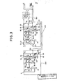
- Fig. 2 is an enlarged circuit diagram of a part of Fig. 1.
- Fig. 3 is an enlarged circuit diagram of another part of Fig. 1.
- Fig. 4 is a partly fragmentary perspective illustration of a vehicle which is removed a vehicle top and a hard roof.
- Fig. 5 is a flow chart of a MPU program.
- Following is a description of an embodiment of the present invention in accordance with the drawings.
- As illustrated in Fig. 1 to Fig.3 , an embodiment of the present device for opening and closing a vehicle top comprises
actuation circuit 200 with the principal clement ofmicrocomputer 1, primarymotor actuation circuit 300 withprimary motor 2, secondarymotor actuation circuit 400 with.secondary motor 3, andcommand switch 500 with top-open command switch 4 and top-close command switch 5. Saidswitches 4 and 5 are push button switches which arc closed only during operation. - In
actuation circuit 200,diodes input terminals actuation circuit 200,MPU 1 input ports SW 4 andSW 6 arc shorted by means ofdiodes diodes diodes input terminals actuation circuit 200 are shorted by means ofdiodes terminals diodes input ports SW 3 andSW 5 ofMPU 1.Resistors Resistor 23 andcondenser 24,resistor 25 andcondenser 26 are integrating circuits for eliminating noise produced via chattering fromrotation synchronization sensors Resistors input ports SW 5 andSW 3 ofMPU 1.Condenser 31, which is connected to reset port RST of MPU 1, is used for power-on reset. The charging resistance is determined withinMPU 1.Diode 32 is used for dischargingcondenser 31.Oscillator 33 is a ceramic oscillator which generates a clock signal to actuateMPU 1.Condensers ceramic oscillator 33.Resistor 36, which is connected toMPU 1 power source input port VDD, andzener diode 37 form a constant-voltage circuit which supplies voltage (5 V) to actuateMPU 1 from the normal 12 V vehicle power source voltage ofpower source terminal 43.Condenser 38 is a stabilizing condenser andcondenser 39 is a ceramic condenser which are used as high frequency noise cutting condensers. Ceramic buzzer 40, which is connected topower source terminal 43, is used to inform the vehicle operator about the actuation state of the vehicle top switching device. The collector of actuation transistor 41 is connected in series to ceramic buzzer 40, and the base of said transistor is connected to the buzzer output port BZ ofMPU 1 by means ofresistor 42, which is used as a base current limiter. Zenerdiode 44, which is connected toinput terminal 46 ofactuation circuit 200, andresistor 45 form a feedback circuit for determining when vehicle top-open command switch 4 of vehicle topcommand switch circuit 500 is in the closed position. When vehicle top-open command switch 4 is in the closed position, it forms a constant-voltage circuit stabilizing voltage identical with the ;MPU 1 actuation power source due to the power source positive polarity ( + ) voltage impression.Condenser 47 is connected in parallel tozener diode 44 and together they form a noise prevention integrating circuit.Resistor 48 is an input protector connected between input port 0/C ofMPU 1 and the non-grounded terminal ofzener diode 44. Pull-down resistor 49 is connected to port 0/C in parallel relationship tozener diode 44 in order to provide normal low-voltage (hereinafter referred to as L).Transistor 50, which is connected toMPU 1output port FET 1 viabase resistor 51, andtransistor 52, which is connected tooutput port FET 3 viabase resistor 53, are both level conversion transistors which convert the ON/OFF voltage forMPU 1output ports FET 1 andFET 3 to vehicle power source voltage ON/OFF. Collector outputs for saidtransistors actuation circuit 200output terminals resistors transistors power source terminal 43 by means ofcollector resistors aforesaid resistors zener diodes 60 and 61, which are built intomotor actuation circuits lead wire terminals terminals transistors terminals aforesaid resistors zener diodes 60, 61. -
Diode 66, which is connected betweenspeed signal terminal 67 ofactuation circuit 200 andMPU 1 speed signal input port SP, prevents 12 V voltage impression onMPU 1 input port SP in order to allow normal vehicle power source (12 v) ON/OFF signal to be impressed as a vehicle speed signal.Transistors MPU 1output ports R 24 andR 13 viabase resistors resistors R 24 andR 13 to 12 V vehicle power source voltage ON/OFF signals. The collectors of saidtransistors power source terminal 43 viacollector resistors relay actuation transistors 74, 75, 76 and 77 are all connected topower source terminal 43, while the collectors of said transistors are connected tooutput terminals transistors 74 and 76 arc connected to collector oflevel conversion transistor 69 viabase resistors level conversion transistor 68 viabase resistors Diodes relay actuation transistors 74, 75, 76 and 77, absorb reverse voltage generated from theswitching relay coils motor actuation circuits power source terminal 43, absorbs reverse voltage in the power line in the same way. -
Motors motor actuation circuits rotation synchronization sensors Motors position feedback switches actuation shafts vehicle top 120, which arc the final output shafts.High frequency coils motors condensers motors Field effect transistors motors field effecl transistors switching relay contacts terminals switching relay contacts switching relay contacts motors high frequency coils relay contacts power terminal 112. - In
motor actuation circuit 400,diodes power source terminal 43 and the top and bottom ofmotor 3, prevent short circuiting of the armature ofmotor 3, and supply power to toactuation circuit 200 by means ofmotor 3 brushes. When vehicle top-open command switch 4 withdiode 115 connected to switching relay coil 92, and vehicle top-close command switch 5 with diode 11G connected to switchingrelay coil 93 are closed, andfield effect transistors motor 3 is impressed topower source terminal 43. Thereupon, current is prevented from flowing into the vehicle power source through transistors 75, 77 or the emitters and collectors oftransistors 74, 76, thus preventing the destruction of saidtransistors 75, 77, 76 and 74. The source and drain offield effect transistors varistors motors field effect transistors - As described in Fig. 4, vehicle top (not shown) is connected between vehicle to stretching
links vehicle 119, said vehicle top can be opened and closed by means of drive shafts ofmotors gear boxes vehicle 119. The aforementioned position feedback switches 98 and 99 are ON during opening and closing of vehicle top and arc OFF when within 10° of full open or full closed positions. (Actuation) - Actuation shall be explained herein in accordance with Fig. 5, which describes the
MP U 1 program, and the aforementioned Fig 1 to Fig.4 - Figure 1 describes the circuits in a non-actuated state. Vehicle top-open command switch 4 and top-
close command switch 5 are both open, and voltage frompower terminal 112 is impressed only to normally open contacts NO of switchingrelay contacts motors motors power source terminal 43 ofactuation circuit 200. Explanation now follows for the actuation process when top-open command switch 4 is pushed to open top 120 when top 120 ofvehicle 119 is in the completely closed state. When top-open command switch 4 is closed, current flows from the positive power source through said switch 4,diode 115 and relay coil 92 to the ground, switchingrelay contact 110 is switched ON and said coil makes contact with normally open contact COM. When switchingrelay contact 110 is ON, power originating from the positive power source is supplied frompower terminal 112, the normally open contact NO of switchingrelay contact 110, common terminal COM,high frequency coil 102 anddiode 113 topower source terminal 43, thus actuatingactuation circuit 200. When power is supplied topower source terminal 43,condenser 31 is charged from the grounded side andMPU 1 is reset by the slow voltage impression to the RST port than the VDD port. During reset,MPU 1output ports R 13,R 24,FET 3,FET 1 and BZ are all at low electric potential (hereinafter low voltage is referred to as "L" and high voltage is referred to as ''H"),transistors transistors transistors transistors 74, 75, 76 and 77 also reach the OFF state. Instep 600, each flag and counter ofMPU 1 undergoes initialization. Whereupon, in the loops ofsteps vehicle 119 due to top operation device malfunction whenswitches 4 and 5 are inadvertently touched or when buffeting wind is encountered by opening (or closing) of said top 120 whilevehicle 119 is moving. Instep 604, it is decided whether or not top-open command switch 4 or top-close command switch 5 has been pushed. In the present embodiment when top-open command switch 4 is closed, voltage from said switch 4 is applied toMPU 1 input port O/C by ,means ofdiode 115 and terminal 46, said port O/C thus registers "H." When top-close command switch 5 is closed and top-open command switch 4 is open, the aforesaid port 0/C registers "L" via pull-down resistor 49. When said input port O/C registers "H," the open flag is set instep 605. In step 606, a check is made to determine whether or not the vehicle speed flag is set. If the results are positive, the process returns to step 600 and the following operations do not occur,that is, whilevehicle 119 is moving, top 120 cannot open or close. If the results of determinations in step 606 are negative, a check is made instep 607 to see whether or not the open flag is set. Since positive results arc derived in the present example, instep 608,MPU 1output port R 13 registers "H,"level conversion transistor 69 registers ON, switchingrelay actuation transistors 74 and 76 are ON, and, by means of current fromoutput terminals relay contacts relay actuation transistors 74, 76 ofactuation circuit 200 maintain the ON state due to voltage supplied from the vehicle power source positive polarity to power source terminal 43 from the normally open terminal NO of switchingrelay contact 110 through common terminal COM,high frequency coil 102 anddiode 113. Switching relay coils 90, 92 are holding. Thus, voltage continues to be supplied topower source terminal 43 ofactuation circuit 200 even when the vehicle operator's hand releases top-open command switch 4 after 0.5 s. - In contrast to the above example, when top-
close command switch 5 is closed, switching relay coils 91 and 93 arc actuated simultaneously, initiating holding. Because the current flowing tomotors relay contacts motors - In
step 610,MPU 1output ports FET 1 andFET 3 register "H," and field effect transistors 62 - 65 register ON due to registered ON states oflevel conversion transistors field effect transistors output terminals actuation circuit 200. Thus, by the grounding ofmotors relay contacts field effect transistors motor 2 andmotor 3 commence rotation in the normal direction, driveshafts - Step 611 is a process in which buzzer 40 activates intermittently at 0.5 s intervals, informing the operator that vehicle top opening (or closing) is in progress. When
MPU 1 output port BZ registers ''H," actuation transistor 41 registers ON and ceramic buzzer 40 sounds. When output port BZ registers "L," actuation transistor 41 registers OFF and buzzer 40 ceases sound emissions. - In
step 612, when rotation ofmotor 2 is faster thanmotor 3, a determination is made as to whether or not the electric potential fromterminal 10 ofrotation sensor 27 has risen from "L" to "H" via signals to input ports SW 4,SW 6. If the electric potential rises, counter I mounted internally inMPU 1 adds a value of one (+1). When the difference in the values of internal counter I, which counts the pulses from input port SW 4, and internal counter II, which counts pulses frominput port SW 6, is 2 or more and the value of counter I is larger, "H" is registered byMPU 1output port FET 1.Level conversion transistor 50 registers ON andfield effect transistors output terminal 54, and the number of rotations decreases due tomotor 2 load changes resulting from interruption of current tomotor 2. Sinceoutput port FET 3 ofMPU 1 registers "L,"level conversion transistor 52 continues in the OFF state, and becauseoutput terminal 55 registers "H," field effect transistors' 64 and 65 maintain the ON state, andmotor 2 andmotor 3 rotations are synchronized. Instep 616, it is determined in the same way whether or not there is a rise inmotor 3 synchronization pulse. When the results of said determination are positive, the same processes are conducted insteps step 619 processing, in contrast to the aforesaid example,motor 3 rotations are synchronized withmotor 2 rotations becauseMPU 1output port FET 3 registers "H" andoutput port FET 1 registers "L." In steps G14 and G18, when the difference in values for internal counters I and II is determined to be less than two (2),motors motors - In
step 620, a check is made to determine whether or not the electric potential ofterminals vehicle top 120 open 10° when the results ofstep 620 determinations are positive, instep 621,motors motors field effect transistors field effect transistors field effect transistors motors drive shafts motors - . In
step 622, it is determined whether or not a rise in vehicle speed signal has occurred. When the result of said determination is positive, then, asvehicle 119 commences travelling in step 623 (via top 120 opening to the target position), field effect transistors 62 - 65 register OFF status, and instep 624, switching relay coils 90 and 92 register OFF entering holding status, and top 120 open actuation is halted. - Step 626 is a process wherein it is determined whether or not
motors rotation synchronization sensors motors vehicle top 120, or stopped when top 120 is completely open and the results ofstep 626 are positive in the same way, instep 627 field effect transistors 62 - 65 register OFF, and after buzzer 40 completes a 1 s actuation period (ON state) informs the vehicle operator instep 628. Then instep 629, switching relay coils 90 and 92 register and maintain OFF status, whereupon, top 120 opening actuation halts. When the results of determination instep 626 is negative, then instep 631, the process returns to step 611 before a 5 ms (millisecond) interval elapses. - The above description of actuation mentions an instance wherein top 120 opens from the completely closed position, however, when top 120 is closed from the completely open position, the same actuation process occurs by means of pushing top-close ; command switch 5.
- In the aforesaid embodiment, while both
motors rotation synchronization sensors - The present invention is a vehicle top-switching device which, because it comprises a means of determining operation time by means of motors for opening and closing said top, switching relays, switching relay actuation transistors, top-open command switch, top-close command switch, a microcomputer, an open/close command determination means, a means for determining vehicle movement status, a holding means, and an actuation means, said device does not require operating power for top opening or closing, possesses a function for preventing malfunctions due to command switch operation time, and a function for preventing top opening or closing while vehicle is in motion, and possesses various other superior functions in a compact size device.
- Although the invention has been described in its preferred form with a certain degree of particularity, it is understood that the present disclosure of the present disclosure of the preferred form has been changed in the details of construction and the combination and arrangement of parts may be resorted to without departing from the spirit and the scope of the invention as hereinafter claimed.
Claims (5)
Applications Claiming Priority (10)
| Application Number | Priority Date | Filing Date | Title |
|---|---|---|---|
| JP27213885A JPS62131818A (en) | 1985-12-03 | 1985-12-03 | Hood opening/closing device for vehicle |
| JP272138/85 | 1985-12-03 | ||
| JP61146710A JPS62133275A (en) | 1986-06-23 | 1986-06-23 | Hood switchgear for car |
| JP146712/86 | 1986-06-23 | ||
| JP146713/86 | 1986-06-23 | ||
| JP146710/86 | 1986-06-23 | ||
| JP61146713A JPS62133278A (en) | 1986-06-23 | 1986-06-23 | Hood switchgear for car |
| JP146711/86 | 1986-06-23 | ||
| JP61146712A JPS62133277A (en) | 1986-06-23 | 1986-06-23 | Hood switchgear for car |
| JP61146711A JPS62133276A (en) | 1986-06-23 | 1986-06-23 | Hood switchgear for car |
Publications (3)
| Publication Number | Publication Date |
|---|---|
| EP0227974A2 true EP0227974A2 (en) | 1987-07-08 |
| EP0227974A3 EP0227974A3 (en) | 1987-07-22 |
| EP0227974B1 EP0227974B1 (en) | 1989-10-11 |
Family
ID=27527773
Family Applications (1)
| Application Number | Title | Priority Date | Filing Date |
|---|---|---|---|
| EP19860116826 Expired EP0227974B1 (en) | 1985-12-03 | 1986-12-03 | A device for opening and closing a vehicle top |
Country Status (2)
| Country | Link |
|---|---|
| EP (1) | EP0227974B1 (en) |
| DE (1) | DE3666192D1 (en) |
Cited By (2)
| Publication number | Priority date | Publication date | Assignee | Title |
|---|---|---|---|---|
| EP0302476A3 (en) * | 1987-08-04 | 1989-06-07 | Asmo Co. Ltd. | Electric-driving device for openable members |
| DE102019113440A1 (en) * | 2019-05-21 | 2020-11-26 | Brose Fahrzeugteile Se & Co. Kommanditgesellschaft, Bamberg | Method for controlling an actuator arrangement for a flap of a motor vehicle |
Citations (5)
| Publication number | Priority date | Publication date | Assignee | Title |
|---|---|---|---|---|
| US2692162A (en) * | 1952-02-04 | 1954-10-19 | Hupp Corp | Dual drive for top-lift mechanisms |
| US3116087A (en) * | 1955-08-02 | 1963-12-31 | Daimler Benz Ag | Drive arrangement for foldable tops of motor vehicles or the like |
| US4093851A (en) * | 1976-12-27 | 1978-06-06 | Burroughs Corporation | Means and methods for detecting the possibility of a failure occurring in the operation of a digital circuit |
| GB1522822A (en) * | 1976-09-22 | 1978-08-31 | Gen Motors Ltd | Electric windscreen wiper systems |
| GB2120427A (en) * | 1982-05-19 | 1983-11-30 | Nissan Motor | Operation mode monitor for microcomputer |
-
1986
- 1986-12-03 EP EP19860116826 patent/EP0227974B1/en not_active Expired
- 1986-12-03 DE DE8686116826T patent/DE3666192D1/en not_active Expired
Patent Citations (5)
| Publication number | Priority date | Publication date | Assignee | Title |
|---|---|---|---|---|
| US2692162A (en) * | 1952-02-04 | 1954-10-19 | Hupp Corp | Dual drive for top-lift mechanisms |
| US3116087A (en) * | 1955-08-02 | 1963-12-31 | Daimler Benz Ag | Drive arrangement for foldable tops of motor vehicles or the like |
| GB1522822A (en) * | 1976-09-22 | 1978-08-31 | Gen Motors Ltd | Electric windscreen wiper systems |
| US4093851A (en) * | 1976-12-27 | 1978-06-06 | Burroughs Corporation | Means and methods for detecting the possibility of a failure occurring in the operation of a digital circuit |
| GB2120427A (en) * | 1982-05-19 | 1983-11-30 | Nissan Motor | Operation mode monitor for microcomputer |
Cited By (2)
| Publication number | Priority date | Publication date | Assignee | Title |
|---|---|---|---|---|
| EP0302476A3 (en) * | 1987-08-04 | 1989-06-07 | Asmo Co. Ltd. | Electric-driving device for openable members |
| DE102019113440A1 (en) * | 2019-05-21 | 2020-11-26 | Brose Fahrzeugteile Se & Co. Kommanditgesellschaft, Bamberg | Method for controlling an actuator arrangement for a flap of a motor vehicle |
Also Published As
| Publication number | Publication date |
|---|---|
| DE3666192D1 (en) | 1989-11-16 |
| EP0227974B1 (en) | 1989-10-11 |
| EP0227974A3 (en) | 1987-07-22 |
Similar Documents
| Publication | Publication Date | Title |
|---|---|---|
| US4575662A (en) | Vehicle power window control circuit | |
| KR0145630B1 (en) | Control apparatus for reversible motor and motor driven power steering system for motor vehicle the same | |
| US4766356A (en) | Device for opening and closing a vehicle top | |
| US4538074A (en) | Power switch | |
| JPS6315177B2 (en) | ||
| US3914675A (en) | Fault detector circuit for electric vehicle control | |
| US4680512A (en) | Fault protection apparatus for traction motor circuit | |
| EP0302476B1 (en) | Electric-driving device for openable members | |
| US5925997A (en) | Drive circuit system for power window | |
| EP0227974A2 (en) | A device for opening and closing a vehicle top | |
| US4017775A (en) | Fault detector circuit with two-fault memory | |
| US4188621A (en) | Alarm system | |
| GB1597210A (en) | Apparatus for switching-off a direction indicator in a motor vehicle after cornering | |
| WO1999056373A1 (en) | Inrush current limiting protection circuit | |
| JPS5922721Y2 (en) | electric car control device | |
| JPS62133277A (en) | Hood switchgear for car | |
| US4169242A (en) | Resistor grid protector | |
| KR850000756Y1 (en) | Door lock | |
| JPS6330867Y2 (en) | ||
| JPH0531671B2 (en) | ||
| JP3096792B2 (en) | Electric power steering device | |
| JPH07312897A (en) | Fault detector | |
| JPH0471723B2 (en) | ||
| JPS62133276A (en) | Hood switchgear for car | |
| JPH0687209B2 (en) | Inductive load drive protection circuit |
Legal Events
| Date | Code | Title | Description |
|---|---|---|---|
| PUAI | Public reference made under article 153(3) epc to a published international application that has entered the european phase |
Free format text: ORIGINAL CODE: 0009012 |
|
| PUAL | Search report despatched |
Free format text: ORIGINAL CODE: 0009013 |
|
| AK | Designated contracting states |
Kind code of ref document: A2 Designated state(s): DE FR GB |
|
| AK | Designated contracting states |
Kind code of ref document: A3 Designated state(s): DE FR GB |
|
| 17P | Request for examination filed |
Effective date: 19870828 |
|
| 17Q | First examination report despatched |
Effective date: 19880311 |
|
| GRAA | (expected) grant |
Free format text: ORIGINAL CODE: 0009210 |
|
| AK | Designated contracting states |
Kind code of ref document: B1 Designated state(s): DE FR GB |
|
| REF | Corresponds to: |
Ref document number: 3666192 Country of ref document: DE Date of ref document: 19891116 |
|
| ET | Fr: translation filed | ||
| PLBE | No opposition filed within time limit |
Free format text: ORIGINAL CODE: 0009261 |
|
| STAA | Information on the status of an ep patent application or granted ep patent |
Free format text: STATUS: NO OPPOSITION FILED WITHIN TIME LIMIT |
|
| 26N | No opposition filed | ||
| PGFP | Annual fee paid to national office [announced via postgrant information from national office to epo] |
Ref country code: GB Payment date: 19991201 Year of fee payment: 14 |
|
| PGFP | Annual fee paid to national office [announced via postgrant information from national office to epo] |
Ref country code: DE Payment date: 19991207 Year of fee payment: 14 |
|
| PGFP | Annual fee paid to national office [announced via postgrant information from national office to epo] |
Ref country code: FR Payment date: 19991208 Year of fee payment: 14 |
|
| PG25 | Lapsed in a contracting state [announced via postgrant information from national office to epo] |
Ref country code: GB Free format text: LAPSE BECAUSE OF NON-PAYMENT OF DUE FEES Effective date: 20001203 |
|
| GBPC | Gb: european patent ceased through non-payment of renewal fee |
Effective date: 20001203 |
|
| PG25 | Lapsed in a contracting state [announced via postgrant information from national office to epo] |
Ref country code: FR Free format text: LAPSE BECAUSE OF NON-PAYMENT OF DUE FEES Effective date: 20010831 |
|
| REG | Reference to a national code |
Ref country code: FR Ref legal event code: ST |
|
| PG25 | Lapsed in a contracting state [announced via postgrant information from national office to epo] |
Ref country code: DE Free format text: LAPSE BECAUSE OF NON-PAYMENT OF DUE FEES Effective date: 20011002 |