EP0227517A1 - Process and apparatus for controlling the amount of metal electrolytically deposited on a continuously moving strip - Google Patents
Process and apparatus for controlling the amount of metal electrolytically deposited on a continuously moving strip Download PDFInfo
- Publication number
- EP0227517A1 EP0227517A1 EP86402522A EP86402522A EP0227517A1 EP 0227517 A1 EP0227517 A1 EP 0227517A1 EP 86402522 A EP86402522 A EP 86402522A EP 86402522 A EP86402522 A EP 86402522A EP 0227517 A1 EP0227517 A1 EP 0227517A1
- Authority
- EP
- European Patent Office
- Prior art keywords
- strip
- metal
- bridge
- bridges
- intensity
- Prior art date
- Legal status (The legal status is an assumption and is not a legal conclusion. Google has not performed a legal analysis and makes no representation as to the accuracy of the status listed.)
- Granted
Links
Images


Classifications
-
- C—CHEMISTRY; METALLURGY
- C25—ELECTROLYTIC OR ELECTROPHORETIC PROCESSES; APPARATUS THEREFOR
- C25D—PROCESSES FOR THE ELECTROLYTIC OR ELECTROPHORETIC PRODUCTION OF COATINGS; ELECTROFORMING; APPARATUS THEREFOR
- C25D21/00—Processes for servicing or operating cells for electrolytic coating
- C25D21/12—Process control or regulation
Definitions
- the present invention relates to the technique of depositing an electrolytic coating on a continuously moving metal strip and relates more particularly to the regulation of metal deposition using a microprocessor.
- the tin is supplied to the tinning installation in the form of bars placed on a copper support serving as an anode.
- the number of tin bars on each support depends on the width of the strip to be tinned.
- tin bars which are in fact consumable electrodes are mounted on conductive slides, which makes it possible to replace them when they are worn, continuously and without stopping the line.
- each tray In each tray are placed a lower rubber roller and a chromed upper roller between which the band is stretched. Together, they form the cathode of the corresponding tank.
- the bridges are supplied with a direct voltage of 24V and receive a current limited to 4500 A.
- the amount of tin deposited is a function of the width of the strip, of the running speed of the latter and of the overall current which is distributed over the different bridges in service.
- the operator sets the target tin rate by intervening directly on the global current (1G). It must first display the width of the strip.
- the tinning rate is kept constant by regulating the current to a value proportional to the line speed.
- this regulation does not prevent under-tinning and over-tinning during intermediate states (speed change, rate change, cut or addition of a bridge).
- a continuous measurement gauge has been installed. This allows the measurement to be transcribed in the form of a graph via a screen. The operator can therefore immediately correct the errors.
- the measurement is based on the principle of X-ray fluorescence.
- the gauge uses two sources of curium 244 with a radioactive period of 17.6 years. The energy released by the source causes an emission of fluorescent rays from iron, part of which is absorbed by tin. It is by determining the quantity of radiation remaining that the tin deposited is calculated.
- the signal processing is as follows. - Conversion of the exponential signal sent by the cells into a linear signal proportional to the coating. - Calculation of the difference between the measurement and the nominal rate targeted. - Possible correction of the signal value of plus or minus 5% depending on the aging of the sources for example. - Finally, a microcomputer records the signals and transmits them to a cathode-ray screen located on the tinning line.
- the gauge scans approximately every 30 seconds. Simultaneously, the transverse profiles of the coating appear, the instantaneous average measured values and those of the last scan, and the minimum threshold authorized by the standards in force for tinning operations such as EURONORM. For comparison, the last saved profile remains on the screen.
- the invention therefore aims to create a method and a device for regulating the electrolytic deposition of a metal coating on a continuously moving strip of metal enabling these drawbacks to be remedied by taking into account the quantities of metal deposited by each bridge and by adapting the settings on the deposit line according to these quantities.
- It therefore relates to a method of regulating the quantity of a metal deposited electrolytically on a strip to be coated continuously scrolling in a deposition installation comprising several reservoirs filled with electrolyte, the strip passing over a conductive roller forming cathode associated with each tank and the coating metal being supplied by bars of said metal carried by conductive bridges forming anodes arranged in each tank on a part of the path of the strip in said tank, characterized in that it consists in calculating at each movement of the strip between two successive bridges, the deposition of metal on each bridge in function of the intensity of the supply current of this bridge, of the speed of the strip and of the efficiency of the bridge, to follow separately each length of strip equal to the distance between two successive bridges by cumulating the successive metal deposits, to be established the balance sheet of the deposit under the last bridge delivering current in order to determine the intensity necessary under this bridge in order to complete the metal deposit, to determine the overall intensity necessary to obtain the desired intensity under this last bridge, and at each acquisition of an average measurement over the entire width
- the process defined above also comprises the phases consisting in determining experimental curves of the yield as a function of the intensity of the supply current of each bridge of the installation, in collecting indications relating to bridges in service or out of service, to establish the analog values of the intensity on each bridge and of the maximum current intensity on all the bridges, to measure the speed of travel of the strip, to establish, set values relating to the quantity of metal to be deposited, to measure the overall quantity of metal deposited using a dipstick periodic lay-up, determining the lower and upper averages of the quantity of metal measured by the gauge on each scan and establishing from the above data a regulation model.
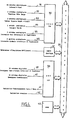
- - Fig.1 is a schematic perspective view with partial cutaway of a tinning tank used in the construction of a tinning installation to which the invention is applied
- - Fig.2 is a schematic top view of the tray of Fig.1
- - Fig.3 is a schematic view of implantation of the tin level measurement gauges in an installation to which the invention is applied
- - Fig.4 is a block diagram of a circuit for processing the data relating to the coating applied to the sheet and for developing the correction coefficients
- - Fig.5 is a flowchart of data acquisition operations relating to the deposited tin rates
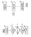
- - Fig.6 is a flow diagram of the fast loop for controlling the tin deposit calculation operations on each bridge
- - Fig.7 is a flowchart for controlling the return of the gauge
- - Fig.8 is a set of yield curve
- tinning tank used in the construction of an installation tinning to which the invention is applied.
- the invention also applies to installations for the electrolytic deposition of coatings of metals other than tin such as chromium, copper or the like.
- the tank comprises a reservoir 1 containing electrolyte not shown.
- a roller 2 In the bottom of the tank is rotatably mounted a roller 2 on which passes continuously a strip B to be coated with a layer of tin.
- the roller 2 is made for example of rubber.
- a second roller 3 Above the reservoir 1 is disposed a second roller 3, for example chrome-plated, of conductive material which ensures the tension of the strip and its transfer into the reservoir 1 from an identical reservoir, not shown, which, with other reservoirs of the same type, arranged upstream and downstream of the tank 1, is part of the tinning installation.
- the roller 3 acts as a cathode associated with the reservoir 1.
- a wringing roller presses the strip B against the roller 3 in order to avoid the formation of electric arcs.
- the strip B passes into the tank 1 between two pairs of supports 4 and 5 (Fig. 2) constituted by copper bars on which are placed side by side vertical tin bars 6 whose feet are engaged in a guide 7 U-shaped.
- the copper bars 4 and 5 form slides for the tin bars and are connected to a corresponding bar 7 for supplying current.
- the strip B therefore passes through two passages formed by the tin bars 6 carried by their corresponding supports 4 and 5, formed respectively on its descent and ascent path in the reservoir 1 filled with electrolyte.
- the supports or bridges 4,5 and the tin bars 6 act as the anode of the device.
- the container thus formed is carried by a frame 10 which also supports the other containers of the installation (not shown).
- a lining 11 made of insulating material is interposed between the frame and the connection 12 of the supports 4,5 to the bar 7 for supplying current.
- a gauge formed by two cells arranged as shown in Fig.3.
- the strip B on the two faces of which a coating of tin has just been deposited passes over a deflector roller 15 opposite which is disposed a first cell 16 intended to measure the coating of tin of a first face of the loop B.
- the cell 16 comprises a source 17 of curium 244 placed on a support 18 mounted oscillating on a base 19 and movable around its axis of oscillation 20 by a pneumatic cylinder 21.
- the strip B then passes over a second deflector roller 22 opposite which is disposed a second cell 23 similar to the cell 16 and intended to measure the coating of tin on the opposite face of the strip B.
- This cell also includes a source 24 of curium 244 placed on a support 25 mounted oscillating on a base 26 and actuated by a pneumatic cylinder 27.
- This circuit includes an analog-digital and digital-analog converter 30, for example of the ADAC 735 type which comprises, for an installation with twelve tinning tanks forty eight analog inputs 31 relating to the intensities of the currents applied to the supports of all the tanks, such as the bridges 4,5 of the tank in Fig. 1 and 2.
- the converter 30 also comprises two analog inputs 32 intended to receive information on the position of the cells 16, 23 from the gauges and two analog inputs 33 intended to receive information relating to the average values of the deposits of tin on the two faces of the strip. .
- the converter 30 further comprises an analog input 34 intended to receive signals relating to the width of the band B processed, two analog inputs 35 relating to the maximum upper and lower intensities and two analog outputs relating to the overall lower and upper intensity to be distributed on the bridges of the installation.
- the converter 30 is connected to a multi-conductor bus 36.
- the circuit of Fig.4 further includes a counter 37 whose input is connected to the output of a band B pulse generator (not shown) and which is also connected to bus 36, a circuit interface 38 of the SBC 519 type manufactured and sold by Intel, with thirty two digital inputs 39 relating to the lower and upper set values of the tin rate to be obtained, thirty two digital inputs 40 relating to the commercial set values, one input 41 for validation of automatic / manual operation and an input 42 of setpoint validation. Circuit 38 is also connected to bus 36.
- circuit in Fig. 4 includes a microprocessor 43 of the Intel 8088 type for example, connected to bus 36 and intended to control changes in the level of tin to be deposited in the various tanks of the installation as a function of the information qu 'he receives.
- a first phase of operation of the installation is the phase of acquiring information relating to the operation in progress.
- the converter 30 receives on its forty-eight inputs measurements of the intensities on the bridges 4.5 of the twelve tanks of the installation.
- the converter 30 reads the currents on each of the bridges. This intensity information is transmitted to the microprocessor 43 which, during phase 51, calculates the values of the tin deposits under each bridge, taking into account the information on the speed of travel of the strip which is supplied to it by the counter 37, of the efficiency of each bridge and of the position of the gauge materializing the width of the strip, these two pieces of information being delivered by the converter 30.
- the microprocessor 43 cumulates information relating to the deposit in progress with the previous deposit.
- the information relating to the last bridge depositing tin during a sweep of the gauge is received on the analog inputs 31 of the converter 30.
- the quantity of tin to be deposited by the last bridge is calculated from the information on set point rates, lower and higher to be obtained, entered by the operator on the inputs 39 of the interface circuit 38. Then, during phase 55, the microprocessor 43 calculates the approximate intensity necessary as a function of the information on the quantity of tin to be deposited by the last bridge and the information on bandwidth, the value of the coating measured by the gauge and the speed of travel of the strip it receives by the bus 36, coming from the converter 30 and the counter 37.
- the microprocessor 43 calculates the efficiency of the bridge from the intensity calculated during phase 55 and this from pre-established curves shown in FIG. 8.
- the microprocessor calculates the necessary intensity corresponding to the yield determined during phase 56, taking into account the value of the coating measured by the gauge and the speed of travel of the strip.
- phase 58 there is a question about the difference between the intensity required and the intensity actually applied to the last bridge.
- phase 60 the strip is brought forward by one step.
- phase 58 If the answer to the interrogation of phase 58 is no, the calculations of phases 56 and 57 are repeated on the data relating to the deposit of tin by a bridge located downstream until the difference in intensity is low.
- the flowchart in Fig.7 is a "slow loop" flowchart which controls drift corrections.
- the acquisition of a measurement made during phase 61 is the reading of the average tin deposit value made by the converter 30 of FIG. 4 at each end of scanning of the gauge of FIG. 3.
- This phase is followed by an interrogation phase 62 relating to the transition from installation to automatic.
- the microprocessor 43 proceeds during phase 65, to the calculation of a gauge yield, that is to say of the ratio between the deposit of tin measured by the gauge and the deposit to be obtained.
- phase 64 The affirmative response to the interrogation of phase 64 causes the setpoint to be validated via the interface circuit 38.
- a regulation current (IC) will be calculated which will be applied to the last bridge.
- TC 2 g / m2
- the actual measurement of the deposited rate does not take place at each step but at each sweep of the gauge.
Abstract
Description
La présente invention est relative à la technique du dépôt d'un revêtement électrolytique sur une bande métallique défilant en continu et se rapporte plus particulièrement à la régulation du dépôt de métal à l'aide d'un microprocesseur.The present invention relates to the technique of depositing an electrolytic coating on a continuously moving metal strip and relates more particularly to the regulation of metal deposition using a microprocessor.
Il est connu pour procéder à l'étamage d'une bande de faire passer cette bande successivement dans plusieurs réservoirs remplis d'électrolyte.It is known to proceed with the tinning of a strip by passing this strip successively through several reservoirs filled with electrolyte.
L'étain est fourni à l'installation d'étamage sous la forme de barres posées sur un support de cuivre faisant office d'anode.The tin is supplied to the tinning installation in the form of bars placed on a copper support serving as an anode.
A titre d'exemple, on peut citer une installation d'étamage comportant douze réservoirs successifs.By way of example, mention may be made of a tinning installation comprising twelve successive tanks.
A raison de deux supports ou ponts par face de métal dans chaque bac, il y a en tout vingt quatre ponts par face.With two supports or bridges per side of metal in each bin, there are a total of twenty four bridges per side.
Le nombre de barres d'étain sur chaque support est fonction de la largeur de la bande à étamer.The number of tin bars on each support depends on the width of the strip to be tinned.
Les barres d'étain qui sont en fait des électrodes consommables sont montées sur des glissières conductrices, ce qui permet de les remplacer lorsqu'elles sont usées, de façon continue et sans arrêt de la ligne.The tin bars which are in fact consumable electrodes are mounted on conductive slides, which makes it possible to replace them when they are worn, continuously and without stopping the line.
Dans chaque bac sont placés un rouleau inférieur en caoutchouc et un rouleau supérieur chromé entre lesquels est tendue la bande. Ensemble, ils forment la cathode du réservoir correspondant.In each tray are placed a lower rubber roller and a chromed upper roller between which the band is stretched. Together, they form the cathode of the corresponding tank.
Les ponts sont alimentés sous une tension continue de 24V et reçoivent un courant limité à 4500 A.The bridges are supplied with a direct voltage of 24V and receive a current limited to 4500 A.
Le taux d'étain déposé est fonction de la largeur de la bande, de la vitesse de défilement de celle-ci et du courant global qui se répartit sur les différents ponts en service.The amount of tin deposited is a function of the width of the strip, of the running speed of the latter and of the overall current which is distributed over the different bridges in service.
L'intensité du courant est donnée par la relation suivante tirée de la loi de Faraday.
l = largeur de la bande en mètres
E = taux d'étain en g/m2
n = rendementThe intensity of the current is given by the following relation taken from Faraday's law.
l = width of the strip in meters
E = tin content in g / m2
n = yield
Dans des installations connues, l'opérateur règle le taux d'étain visé en intervenant directement sur le courant global (1G). Il doit préalablement afficher la largeur de la bande. Le taux d'étamage est maintenu constant par régulation du courant à une valeur proportionnelle à la vitesse de la ligne. Cependant, cette régulation ne permet pas d'éviter le sous-étamage et le sur-étamage lors des états intermédiaires (changement de vitesse, changement de taux, coupure ou rajout d'un pont).In known installations, the operator sets the target tin rate by intervening directly on the global current (1G). It must first display the width of the strip. The tinning rate is kept constant by regulating the current to a value proportional to the line speed. However, this regulation does not prevent under-tinning and over-tinning during intermediate states (speed change, rate change, cut or addition of a bridge).
En effet, la quantité d'étain déposé est égale à :
A l'état stable toutes les vitesses de passage sous les ponts sont identiques, donc on a :
A chaque transitoire cependant, cette relation n'est plus vraie, tous les vi pouvant être différents, et donc la quantité d'étain peut différer de plus de 20% de la valeur visée.With each transient, however, this relationship is no longer true, as all of the vi can be different, and therefore the quantity of tin can differ by more than 20% from the target value.
Dans un passé récent, la mesure du taux d'étain déposé était effectuée comme suit.In the recent past, the measurement of the rate of deposited tin was carried out as follows.
Les opérateurs affichaient à l'aide d'une table, une référence de courant en fonction du revêtement à effectuer. Une mesure était effectuée par contrôle destructif. On réajustait alors le courant. Cette mesure prenait entre quelques minutes et trois quarts d'heure et il fallait recommencer plusieurs fois ces opérations avant d'obtenir un résultat satisfaisant.The operators displayed using a table, a current reference according to the coating to be made. A measurement was made by destructive testing. The current was then readjusted. This measurement took between a few minutes and three quarters of an hour and it was necessary to repeat these operations several times before obtaining a satisfactory result.
Etant donnée l'inertie du système, sur des programmes courts, le réglage était souvent obtenu en fin d'opération. De plus, pour éviter des litiges, on visait dès le départ un taux plus élevé que le taux nominal. D'où un coût excessif de l'opération d'étamage.Given the inertia of the system, on short programs, the setting was often obtained at the end of the operation. In addition, to avoid litigation, we aimed at a rate higher than the nominal rate from the start. Hence the excessive cost of the tinning operation.
Plus récemment encore, une jauge de mesure en continu a été installée. Celle-ci permet de retranscrire la mesure sous la forme d'un graphe par l'intermédiaire d'un écran. L'opérateur peut donc corriger immédiatement les erreurs.More recently, a continuous measurement gauge has been installed. This allows the measurement to be transcribed in the form of a graph via a screen. The operator can therefore immediately correct the errors.
Cette jauge fonctionne de la façon suivante.This gauge works as follows.
La mesure est basée sur le principe de la fluorescence X. La jauge utilise deux sources de curium 244 d'une période radioactive de 17,6 ans. L'énergie libérée par la source provoque une émission de rayons fluorescents provenant du fer dont une partie est absorbée par l'étain. C'est en déterminant la quantité de rayonnement restante que l'on calcule l'étain déposé.The measurement is based on the principle of X-ray fluorescence. The gauge uses two sources of curium 244 with a radioactive period of 17.6 years. The energy released by the source causes an emission of fluorescent rays from iron, part of which is absorbed by tin. It is by determining the quantity of radiation remaining that the tin deposited is calculated.
Le traitement du signal est le suivant.
- Conversion du signal exponentiel envoyé par les cellules en un signal linéaire proportionnel au revêtement.
- Calcul de l'écart entre la mesure et le taux nominal visé.
- Correction possible de la valeur du signal de plus ou moins 5% selon le vieillissement des sources par exemple.
- Enfin, un microcalculateur enregistre les signaux et les transmet à un écran cathodique situé sur la ligne d'étamage.The signal processing is as follows.
- Conversion of the exponential signal sent by the cells into a linear signal proportional to the coating.
- Calculation of the difference between the measurement and the nominal rate targeted.
- Possible correction of the signal value of plus or minus 5% depending on the aging of the sources for example.
- Finally, a microcomputer records the signals and transmits them to a cathode-ray screen located on the tinning line.
La jauge effectue un balayage toutes les 30 secondes environ. Simultanément, apparaissent les profils transversaux du revêtement, les valeurs moyennes mesurées instantanées et celles du dernier balayage, et le seuil minimal autorisé par les normes en vigueur pour les opérations d'étamage telles qu'EURONORM. A titre de comparaison, le dernier profil enregistré reste sur l'écran.The gauge scans approximately every 30 seconds. Simultaneously, the transverse profiles of the coating appear, the instantaneous average measured values and those of the last scan, and the minimum threshold authorized by the standards in force for tinning operations such as EURONORM. For comparison, the last saved profile remains on the screen.
Avec les techniques connues évoquées plus haut, on se trouve en présence du problème de la variation du taux d'étain à chaque transitoire de vitesse.With the known techniques mentioned above, we are faced with the problem of the variation of the tin rate at each speed transient.
L'invention vise donc à créer un procédé et un dispositif de régulation du dépôt électrolytique d'un revêtement métallique sur une bande de métal défilant en continu permettant de remédier à ces inconvénients en prenant en compte les quantités de métal déposées par chaque pont et en adaptant les réglages sur la ligne de dépôt en fonction de ces quantités.The invention therefore aims to create a method and a device for regulating the electrolytic deposition of a metal coating on a continuously moving strip of metal enabling these drawbacks to be remedied by taking into account the quantities of metal deposited by each bridge and by adapting the settings on the deposit line according to these quantities.
Elle a donc pour objet un procédé de régulation de la quantité d'un métal déposée par voie électrolytique sur une bande à revêtir défilant en continue dans une installation de dépôt comportant plusieurs réservoirs remplis d'électrolyte, la bande passant sur un rouleau conducteur formant cathode associé à chaque réservoir et le métal de revêtement étant fourni par des barres dudit métal portées par des ponts conducteurs formant anodes disposés dans chaque réservoir sur une partie du trajet de la bande dans ledit réservoir, caractérisé en ce qu'il consiste à calculer à chaque déplacement de la bande entre deux ponts successifs, le dépôt de métal sur chaque pont en fonction de l'intensité du courant d'alimentation de ce pont, de la vitesse de la bande et du rendement du pont, à suivre séparément chaque longueur de bande égale à la distance entre deux ponts successifs en cumulant les dépôts de métal successifs, à établir le bilan du dépôt sous le dernier pont débitant du courant afin de déterminer l'intensité nécessaire sous ce pont afin de compléter le dépôt de métal, à déterminer l'intensité globale nécessaire pour obtenir l'intensité désirée sous ce dernier pont, et à chaque acquisition d'une mesure moyenne sur toute la largeur de la bande, à calculer en tenant compte de la distance de transfert, l'écart entre cette valeur moyenne et une valeur de consigne préétablie en déterminant un coefficient correcteur des rendements théoriques du dépôt de métal sous chaque pont.It therefore relates to a method of regulating the quantity of a metal deposited electrolytically on a strip to be coated continuously scrolling in a deposition installation comprising several reservoirs filled with electrolyte, the strip passing over a conductive roller forming cathode associated with each tank and the coating metal being supplied by bars of said metal carried by conductive bridges forming anodes arranged in each tank on a part of the path of the strip in said tank, characterized in that it consists in calculating at each movement of the strip between two successive bridges, the deposition of metal on each bridge in function of the intensity of the supply current of this bridge, of the speed of the strip and of the efficiency of the bridge, to follow separately each length of strip equal to the distance between two successive bridges by cumulating the successive metal deposits, to be established the balance sheet of the deposit under the last bridge delivering current in order to determine the intensity necessary under this bridge in order to complete the metal deposit, to determine the overall intensity necessary to obtain the desired intensity under this last bridge, and at each acquisition of an average measurement over the entire width of the strip, to be calculated taking into account the transfer distance, the difference between this average value and a preset preset value in determining nt a correction coefficient for the theoretical yields of the metal deposit under each bridge.
Suivant une caractéristique particulière de l'invention, le procédé défini ci-dessus comporte en outre les phases consistant à déterminer des courbes expérimentales du rendement en fonction de l'intensité du courant d'alimentation de chaque pont de l'installation, à recueillir des indications relatives aux ponts en service ou hors service, à établir les valeurs analogiques de l'intensité sur chaque pont et de l'intensité maximale du courant sur l'ensemble des ponts, à mesurer la vitesse de défilement de la bande, à établir, des valeurs de consigne relatives à la quantité de métal à déposer, à mesurer la quantité globale de métal déposée à l'aide d'une jauge à ba layage périodique, à déterminer les moyennes inférieure et supérieure de la quantité de métal mesurée par la jauge à chaque balayage et à établir à partir des données précitées un modèle de régulation.According to a particular characteristic of the invention, the process defined above also comprises the phases consisting in determining experimental curves of the yield as a function of the intensity of the supply current of each bridge of the installation, in collecting indications relating to bridges in service or out of service, to establish the analog values of the intensity on each bridge and of the maximum current intensity on all the bridges, to measure the speed of travel of the strip, to establish, set values relating to the quantity of metal to be deposited, to measure the overall quantity of metal deposited using a dipstick periodic lay-up, determining the lower and upper averages of the quantity of metal measured by the gauge on each scan and establishing from the above data a regulation model.
L'invention sera mieux comprise à l'aide de la description qui va suivre, donnée uniquement à titre d'exemple et faite en se référant aux dessins annexés, sur lesquels :
- la Fig.1 est une vue schématique en perspective avec arrachement partiel d'un bac d'étamage entrant dans la construction d'une installation d'étamage à laquelle est appliquée l'invention;
- la Fig.2 est une vue schématique de dessus du bac de la Fig.1;
- la Fig.3 est une vue schématique d'implantation des jauges de mesure du taux d'étain dans une installation à laquelle est appliquée l'invention;
- la Fig.4 est un schéma synoptique d'un circuit de traitement des données relatives au revêtement appliqué à la tôle et d'élaboration des coefficients de correction;
- la Fig.5 est un organigramme des opérations d'acquisition des données relatives aux taux d'étain déposé;
- la Fig.6 est un organigramme de la boucle rapide de commande des opérations de calcul du dépôt d'étain sur chaque pont;
- la Fig.7 est un organigramme de commande du retour de jauge; et
- la Fig.8 est une ensemble de courbes de rendement des ponts de l'installation pour divers courants d'alimentation.The invention will be better understood with the aid of the description which follows, given solely by way of example and made with reference to the appended drawings, in which:
- Fig.1 is a schematic perspective view with partial cutaway of a tinning tank used in the construction of a tinning installation to which the invention is applied;
- Fig.2 is a schematic top view of the tray of Fig.1;
- Fig.3 is a schematic view of implantation of the tin level measurement gauges in an installation to which the invention is applied;
- Fig.4 is a block diagram of a circuit for processing the data relating to the coating applied to the sheet and for developing the correction coefficients;
- Fig.5 is a flowchart of data acquisition operations relating to the deposited tin rates;
- Fig.6 is a flow diagram of the fast loop for controlling the tin deposit calculation operations on each bridge;
- Fig.7 is a flowchart for controlling the return of the gauge; and
- Fig.8 is a set of yield curves of the installation bridges for various supply currents.
Sur la Fig.1, on a représenté un bac d'étamage entrant dans la construction d'une installation d'étamage à laquelle est appliquée l'invention.In Fig.1, there is shown a tinning tank used in the construction of an installation tinning to which the invention is applied.
Il convient toutefois de remarquer que l'invention s'applique également à des installation de dépôt électrolytique de revêtements de métaux autres que l'étain tels que le chrome, le cuivre ou autre.It should however be noted that the invention also applies to installations for the electrolytic deposition of coatings of metals other than tin such as chromium, copper or the like.
Le bac comprend un réservoir 1 contenant de l'électrolyte non représenté.The tank comprises a
Dans le fond du bac est monté à rotation un rouleau 2 sur lequel passe en continu une bande B à revêtir d'une couche d'étain. Le rouleau 2 est réalisé par exemple en caoutchouc. Au-dessus du réservoir 1 est disposé un second rouleau 3, par exemple chromé, en matière conductrice qui assure la tension de la bande et son transfert dans le réservoir 1 à partir d'un réservoir identique non représenté qui, avec d'autres réservoirs de même type, disposés en amont et en aval du réservoir 1, fait partie de l'installation d'étamage.In the bottom of the tank is rotatably mounted a
Le rouleau 3 fait office de cathode associée au résevoir 1.The
Un rouleau essoreur (non representé) plaque la bande B contre le rouleau 3 afin d'éviter la formation d'arcs électriques.A wringing roller (not shown) presses the strip B against the
La bande B passe dans le réservoir 1 entre deux paires de supports 4 et 5 (Fig.2) constitués par des barres de cuivre sur lesquelles sont disposées côte à côte des barres d'étain verticales 6 dont les pieds sont engagés dans un guide 7 en forme de U.The strip B passes into the
Les barres de cuivre 4 et 5 forment des glissières pour les barres d'étain et sont connectées à une barre 7 correspondante d'amenée de courant.The copper bars 4 and 5 form slides for the tin bars and are connected to a
La bande B défile donc dans deux passages formés par les barres d'étain 6 portées par leurs supports correspondants 4 et 5, ménagés respectivement sur son trajet de descente et de montée dans le réservoir 1 rempli d'électrolyte.The strip B therefore passes through two passages formed by the tin bars 6 carried by their
Les supports ou ponts 4,5 et les barres d'étain 6 font office d'anode du dispositif.The supports or
Le bac ainsi constitué est porté par un bâti 10 qui supporte également les autres bacs de l'installation (non représentés).The container thus formed is carried by a
Une garniture 11 en matière isolante est interposée entre le bâti et la connexion 12 des supports 4,5 à la barre 7 d'amenée de courant.A lining 11 made of insulating material is interposed between the frame and the
En aval du denier bac de l'installation est installée, une jauge formée de deux cellules disposées de la façon représentée à la Fig.3.Downstream of the last tank of the installation is installed, a gauge formed by two cells arranged as shown in Fig.3.
A la sortie de l'installation, la bande B sur les deux faces de laquelle vient d'être déposé un revêtement d'étain passe sur un rouleau déflecteur 15 en regard duquel est disposée une première cellule 16 destinée à mesurer le revêtement d'étain d'une première face de la boucle B. La cellule 16 comporte une source 17 de curium 244 placée sur un support 18 monté oscillant sur un socle 19 et déplaçable autour de son axe d'oscillation 20 par un vérin pneumatique 21.At the exit of the installation, the strip B on the two faces of which a coating of tin has just been deposited passes over a
La bande B passe ensuite sur un second rouleau déflecteur 22 en regard duquel est disposée une seconde cellule 23 analogue à la cellule 16 et destinée à mesurer le revêtement d'étain de la face opposée de la bande B.The strip B then passes over a
Cette cellule comporte elle aussi une source 24 de curium 244 placée sur un support 25 monté oscillant sur un socle 26 et actionné par un vérin pneumatique 27.This cell also includes a
Les sorties (non représentées des deux cellules 16 et 23 de la jauge sont connectées à des entrées correspondantes du circuit de traitement de la Fig.4 qui va maintenant être décrit.The outputs (not shown from the two
Ce circuit comprend un convertisseur analogique-numérique et numérique-analogique 30, par exemple du type ADAC 735 qui comporte, pour une installation à douze bacs d'étamage quarante huit entrées analogiques 31 relatives aux intensités des courants appliqués aux supports de tous les bacs, tels que les ponts 4,5 du bac des Fig.1 et 2.This circuit includes an analog-digital and digital-
Le convertisseur 30 comporte en outre deux entrées analogiques 32 destinées à recevoir des informations de position des cellules 16,23 des jauges et deux entrées analogiques 33 destinées à recevoir des informations relatives aux valeurs moyennes des dépôts d'étain sur les deux faces de la bande.The
Le convertisseur 30 comporte de plus une entrée analogique 34 destinée à recevoir des signaux concernant la largeur de la bande B traitée, deux entrées analogiques 35 concernant les intensités maximales inférieure et supérieure et deux sorties analogiques relatives à l'intensité globale inférieure et supérieure à répartir sur les ponts de l'installation.The
Le convertisseur 30 est connectée à un bus à conducteurs multiples 36.The
Le circuit de la Fig.4 comporte en outre un compteur 37 dont l'entrée est connectée à la sortie d'un générateur d'impulsions de défilement de la bande B (non représenté) et qui est également connecté au bus 36, un circuit d'interface 38 du type SBC 519 fabriqué et vendu par Intel, à trente deux entrées numériques 39 relatives aux valeurs de consigne inférieure et supérieure du taux d'étain à obtenir, trente deux entrées numériques 40 relatives aux valeurs de consigne commerciales, une entrée 41 de validation du fonctionnement automatique/manuel et une entrée 42 de validation de consigne. Le circuit 38 est également connecté au bus 36.The circuit of Fig.4 further includes a
Enfin, le circuit de la Fig.4 comporte un microprocesseur 43 du type Intel 8088 par exemple, connecté au bus 36 et destiné à commander les modifications du taux d'étain à déposer dans les divers bacs de l'installation en fonction des informations qu'il reçoit.Finally, the circuit in Fig. 4 includes a
Le fonctionnement de l'installation va maintenant être décrit en référence à la Fig.4 et aux organigrammes des Fig.5 à 7.The operation of the installation will now be described with reference to Fig. 4 and to the flowcharts in Figs. 5 to 7.
Une première phase de fonctionnement de l'installation est la phase d'acquisition des informations relatives à l'opération en cours.A first phase of operation of the installation is the phase of acquiring information relating to the operation in progress.
Le convertisseur 30 reçoit sur ses quarante huit entrées des mesures des intensités sur les ponts 4,5 des douze bacs de l'installation.The
Au cours de la phase 50 de l'organigramme de la Fig.5, le convertisseur 30 procède à la lecture des courants sur chacun des ponts. Ces informations d'intensité sont transmises au microprocesseur 43 qui, au cours de la phase 51, calcule les valeurs des dépôts d'étain sous chaque pont, compte tenu de l'information de vitesse de défilement de la bande qui lui est fournie par le compteur 37, du rendement de chaque pont et de la position de la jauge matérialisant la largeur de la bande, ces deux informations étant délivrées par le convertisseur 30.During
Au cours de la phase 52, le microprocesseur 43 procède au cumul des informations relatives au dépôt en cours avec le dépôt précédent.During
Ensuite, comme représenté sur l'organigramme de la Fig.6, il y a détermination du dernier pont déposant de l'étain. Cette opération est réalisée au cours de la phase 53 de l'organigramme de "boucle rapide" de la Fig.6.Then, as shown in the flow diagram of Fig. 6, there is determination of the last bridge depositing the tin. This operation is carried out at during
L'information relative au dernier pont déposant de l'étain au cours d'un balayage de la jauge est reçue sur les entrées analogiques 31 du convertisseur 30.The information relating to the last bridge depositing tin during a sweep of the gauge is received on the
Au cours de la phase 54, il y a calcul de la quantité d'étain à déposer par le dernier pont à partir des informations de consignes de taux d'étain, inférieur et supérieur à obtenir introduites par l'opérateur sur les entrées 39 du circuit d'interface 38. Ensuite, au cours de la phase 55, le microprocesseur 43 calcule l'intensité approximative nécessaire en fonction de l'information de la quantité d'étain à déposer par le dernier pont et des informations de largeur de bande, de la valeur du revêtement mesurée par la jauge et de la vitesse de défilement de la bande, qu'il reçoit par le bus 36, en provenance du convertisseur 30 et du compteur 37.During
Au cours de la phase 56, le microprocesseur 43 calcule le rendement du pont à partir de l'intensité calculée au cours de la phase 55 et ceci à partir de courbes pré-établies représentées à la Fig.8.During
Puis, au cours de la phase 57, le microprocesseur calcule l'intensité nécessaire correspondant au rendement déterminé au cours de la phase 56, en tenant compte de la valeur du revêtement mesuré par la jauge et de la vitesse de défilement de la bande.Then, during
Au cours de la phase 58, il y a interrogation au sujet de l'écart entre l'intensité nécessaire et l'intensité réellement appliquée au dernier pont.During
Si l'écart est faible, il y a envoi au cours de la phase 59 de signaux correspondant à l'intensité globale calculée qui apparaissent sur les sorties ana logiques 36 du convertisseur 30, cette intensité étant à répartir sur les divers ponts de l'installation.If the difference is small, there is a sending during
Enfin, au cours de la phase 60, on provoque l'avance de la bande d'un pas.Finally, during
Si la réponse à l'interrogation de la phase 58 est non, on répète les calculs des phases 56 et 57 sur les données relatives au dépôt d'étain par un pont situé en aval jusqu'à ce que l'écart d'intensité soit faible.If the answer to the interrogation of
L'organigramme de la Fig.7 est un organigramme de " boucle lente " qui commande les corrections de dérive.The flowchart in Fig.7 is a "slow loop" flowchart which controls drift corrections.
L'acquisition d'une mesure faite au cours de la phase 61 est la lecture de la valeur moyenne de dépôt d'étain faite par le convertisseur 30 de la Fig.4 à chaque fin de balayage de la jauge de la Fig. 3.The acquisition of a measurement made during
Cette phase est suivie d'une phase 62 d'interrogation relative au passage de l'installation en automatique.This phase is followed by an
Si la réponse est non, on passe à une phase d'interrogation 63 relative au démarrage de la ligne.If the answer is no, we pass to an
Si la réponse à cette nouvelle interrogation est non, on procéde à une troisième interrogation au cours de la phase 64 en ce qui concerne le changement de taux d'étain.If the answer to this new interrogation is no, a third interrogation is carried out during
En cas de réponse négative, le microprocesseur 43 procède au cours de la phase 65, au calcul d'un rendement de jauge, c'est à dire du rapport entre le dépôt d'étain mesuré par la jauge et le dépôt à obtenir.In the event of a negative response, the
Si les réponses aux trois interrogations précédentes sont oui, on laisse passer un balayage de la jauge et on procède à de nouvelles interrogations.If the answers to the three preceding interrogations are yes, one lets pass a sweep of the gauge and one proceeds to new interrogations.
Pendant ce temps, le réponse affirmative à l'interrogation relative au passage en automatique provoque la validation du fonctionnement automatique.During this time, the affirmative answer to the interrogation relating to the passage to automatic causes the validation of the automatic operation.
La réponse affirmative à l'interrogation relative au démarrage de ligne commande le générateur d'impuslions (non représenté) qui est associé au compteur 37 de la Fig.4.The affirmative response to the query relating to line starting controls the pulse generator (not shown) which is associated with the
La réponse affirmative à l'interrogation de la phase 64 provoque la validation de la consigne par l'intermédiaire du circuit d'interface 38.The affirmative response to the interrogation of
Le procédé qui vient d'être décrit présente vis à vis des procédés connus les avantages suivants.The process which has just been described has the following advantages over known processes.
Il permet de prendre en compte tous les transitoires tels que la variation de la vitesse de défilement de la bande, les arrêts ou les mises en service des ponts.It makes it possible to take into account all the transients such as the variation of the speed of travel of the strip, the stops or the putting into service of the bridges.
Il tient compte du rendement de l'électrolyse sous chaque pont, ce qui permet d'avoir une grande précision dans l'obtention directe du bon étamage à chaque changement de consigne.It takes into account the efficiency of the electrolysis under each bridge, which allows great precision in the direct obtaining of good tinning at each set point change.
Ceci est particulièrement important dans le cas de revêtements minces ou lorsque l'intensité maximale des ponts est faible, car on a alors des rendements pouvant être très bas sur les premiers ponts.This is particularly important in the case of thin coatings or when the maximum intensity of the bridges is low, since there are then yields which can be very low on the first bridges.
Les corrections de courants sont également faibles en valeurs absolues et les interventions de l'opérateur sont plus précises.Current corrections are also small in absolute values and operator intervention is more precise.
Il permet enfin d'obtenir un faible écart entre le dépôt d'étain obtenu et la valeur de consigne.Finally, it makes it possible to obtain a small difference between the tin deposit obtained and the set value.
On donne ci-après à titre d'exemple le déroulement des opérations de régulation du dépôt d'étain dans une installation d'étamage à douze bacs et vingt quatre ponts.An example is given below of the sequence of operations for regulating the deposit of tin in a tinning installation with twelve tanks and twenty four bridges.
- Vitesse de la ligne
- Largeur de la bande
- Taux d'étain visé
- Courant débité par pont- Line speed
- Band width
- Targeted tin rate
- Current charged by bridge
Il faut tout d'abord savoir qu'à chaque fois que l'on boucle le programme, la bande a parcouru environ 4 mètres. Ceci correspond à un pas de programme et à la distance séparant le pont N du pont N + 1.First of all, you should know that each time the program is finished, the tape has traveled approximately 4 meters. This corresponds to a program step and to the distance separating the N bridge from the N + 1 bridge.
Lors du premier pas N = 1 et à chaque pas on ajoutera 1 à N. On demandera donc à chaque pas de mettre un pont supplémentaire en aval, à l'intensité maximum possible.During the first step N = 1 and at each step we will add 1 to N. We will therefore ask each step to put an additional bridge downstream, at the maximum possible intensity.
A chaque pas, on calculera le taux d'étain théorique déposé sous chaque pont.At each step, the theoretical tin rate deposited under each bridge will be calculated.

Afin de simplifier l'exemple, on prendra ici pour principe qu'un pont dépose théoriquement 0,5 g/m² d'étain sur le métal.In order to simplify the example, it will be assumed here that a bridge theoretically deposits 0.5 g / m² of tin on the metal.
Une fois le calcul de l'étain déposé effectué, on regardera le taux obtenu sous le dernier pont mis à l'intensité maximale. Deux cas de traitement possible suivant que le taux est supérieur ou inférieur à ce qui l'on vise. Dans les applications numériques cette intensité maximale est prise à 4500 Ampères.Once the calculation of the deposited tin has been carried out, we will look at the rate obtained under the last bridge set to maximum intensity. Two cases of possible treatment depending on whether the rate is higher or lower than what is targeted. In digital applications this maximum intensity is taken at 4500 Amps.
Dans le premier cas, on calculera un courant (IC) de régulation que l'on appliquera sur le dernier pont.In the first case, a regulation current (IC) will be calculated which will be applied to the last bridge.
En reprenant l'exemple précédent et en supposant que le taux visé (TV) est de l,8 g/m², on s'apercevra lors du pas 4 que le taux calculé (TC = 2 g/m²) est supérieur au taux visé TV. On calculera alors la correction C.
C = TC - TVUsing the previous example and assuming that the target rate (TV) is 1.8 g / m², it will be seen in
C = TC - TV
On en déduira le courant IC nécessaire sur le pont 4 pour obtenir 1,8 g/m².We will deduct the IC current required on
Dans le deuxième cas, on ajoutera des ponts supplémentaires pour arriver au premier cas.In the second case, we will add additional bridges to arrive at the first case.
Quand les calculs sont terminés, on envoie le courant demandé.When the calculations are finished, we send the requested current.
Suite de l'exemple précédent (TV = 1,8 g/m²)

Une fois le courant envoyé, on passe au pas suivant :
P + 1Once the current is sent, we go to the next step:
P + 1
On prend en compte les nouvelles données.We take into account the new data.
C'est alors qu'intervient la mesure du taux réellement déposé (MJ).Then comes the measurement of the rate actually deposited (MJ).
Celui-ci permettra de déterminer le nouveau Rendement Jauge (RJ) qui interviendra dans les calculs au pas suivant.
RJ - 3/4 (1 - (MJ/TV) )This will determine the new Yield Gauge (RJ) which will be used in the calculations at the next step.
RJ - 3/4 (1 - (MJ / TV))
(Le coefficient 3/4 est là pour amortir la correction du rendement).(The
La mesure réelle du taux déposé n'intervient pas à chaque pas mais a chaque balayage de la jauge.The actual measurement of the deposited rate does not take place at each step but at each sweep of the gauge.
Claims (5)
Priority Applications (1)
| Application Number | Priority Date | Filing Date | Title |
|---|---|---|---|
| AT86402522T ATE52546T1 (en) | 1985-11-19 | 1986-11-13 | METHOD AND DEVICE FOR CONTROL OF METAL DEPOSITION BY ELECTROLYTIC WAY ON A CONTINUOUSLY RUNNING BELT. |
Applications Claiming Priority (2)
| Application Number | Priority Date | Filing Date | Title |
|---|---|---|---|
| FR8517095 | 1985-11-19 | ||
| FR8517095A FR2590278B1 (en) | 1985-11-19 | 1985-11-19 | METHOD AND DEVICE FOR CONTROLLING THE QUANTITY OF A METAL ELECTROLYTICALLY DEPOSITED ON A CONTINUOUSLY TRAVELING STRIP |
Publications (2)
| Publication Number | Publication Date |
|---|---|
| EP0227517A1 true EP0227517A1 (en) | 1987-07-01 |
| EP0227517B1 EP0227517B1 (en) | 1990-05-09 |
Family
ID=9324962
Family Applications (1)
| Application Number | Title | Priority Date | Filing Date |
|---|---|---|---|
| EP86402522A Expired - Lifetime EP0227517B1 (en) | 1985-11-19 | 1986-11-13 | Process and apparatus for controlling the amount of metal electrolytically deposited on a continuously moving strip |
Country Status (9)
| Country | Link |
|---|---|
| US (1) | US4699694A (en) |
| EP (1) | EP0227517B1 (en) |
| JP (1) | JPH0765238B2 (en) |
| AT (1) | ATE52546T1 (en) |
| CA (1) | CA1308686C (en) |
| DE (1) | DE3671045D1 (en) |
| ES (1) | ES2016270B3 (en) |
| FR (1) | FR2590278B1 (en) |
| GR (1) | GR3000694T3 (en) |
Cited By (1)
| Publication number | Priority date | Publication date | Assignee | Title |
|---|---|---|---|---|
| AT516722A4 (en) * | 2015-07-27 | 2016-08-15 | Berndorf Band Gmbh | Method and device for producing a metal strip of uniform thickness |
Families Citing this family (6)
| Publication number | Priority date | Publication date | Assignee | Title |
|---|---|---|---|---|
| FR2704241B1 (en) * | 1993-04-22 | 1995-06-30 | Lorraine Laminage | METHOD FOR REGULATING ELECTRO-DEPOSITION ON A METAL STRIP. |
| US5668570A (en) * | 1993-06-29 | 1997-09-16 | Ditzik; Richard J. | Desktop computer with adjustable flat panel screen |
| US5914022A (en) * | 1996-01-05 | 1999-06-22 | Lowry; Patrick Ross | Method and apparatus for monitoring and controlling electrodeposition of paint |
| US6019886A (en) * | 1996-09-17 | 2000-02-01 | Texas Instruments Incorporated | Comparator for monitoring the deposition of an electrically conductive material on a leadframe to warn of improper operation of a leadframe electroplating process |
| US6187153B1 (en) * | 1997-09-16 | 2001-02-13 | Texas Instruments Incorporated | Comparator for monitoring the deposition of an electrically conductive material on a leadframe to warn of improper operation of a leadframe electroplating process |
| JP5884169B2 (en) * | 2012-03-01 | 2016-03-15 | Jfeスチール株式会社 | Automatic monitoring system and method for self-fluxing electrode consumption in electroplated steel sheet production line |
Citations (3)
| Publication number | Priority date | Publication date | Assignee | Title |
|---|---|---|---|---|
| GB688189A (en) * | 1950-12-13 | 1953-02-25 | United States Steel Corp | Electrical measuring instrument |
| DE2347759A1 (en) * | 1973-09-22 | 1975-04-24 | Oelsch Fernsteuergeraete | Electrolytic plating thickness measurement - by electrode array current density adjusted to that in bath comparing layer thickness |
| US4240881A (en) * | 1979-02-02 | 1980-12-23 | Republic Steel Corporation | Electroplating current control |
Family Cites Families (1)
| Publication number | Priority date | Publication date | Assignee | Title |
|---|---|---|---|---|
| JPH0233800B2 (en) * | 1983-08-23 | 1990-07-30 | Nippon Steel Corp | RENZOKUDENKIMETSUKINIOKERUMETSUKIDENRYUSEIGYOHOHO |
-
1985
- 1985-11-19 FR FR8517095A patent/FR2590278B1/en not_active Expired
-
1986
- 1986-11-13 DE DE8686402522T patent/DE3671045D1/en not_active Expired - Lifetime
- 1986-11-13 EP EP86402522A patent/EP0227517B1/en not_active Expired - Lifetime
- 1986-11-13 ES ES86402522T patent/ES2016270B3/en not_active Expired - Lifetime
- 1986-11-13 AT AT86402522T patent/ATE52546T1/en not_active IP Right Cessation
- 1986-11-18 CA CA000523178A patent/CA1308686C/en not_active Expired - Lifetime
- 1986-11-18 US US06/932,013 patent/US4699694A/en not_active Expired - Lifetime
- 1986-11-19 JP JP61276404A patent/JPH0765238B2/en not_active Expired - Fee Related
-
1990
- 1990-08-03 GR GR90400556T patent/GR3000694T3/en unknown
Patent Citations (3)
| Publication number | Priority date | Publication date | Assignee | Title |
|---|---|---|---|---|
| GB688189A (en) * | 1950-12-13 | 1953-02-25 | United States Steel Corp | Electrical measuring instrument |
| DE2347759A1 (en) * | 1973-09-22 | 1975-04-24 | Oelsch Fernsteuergeraete | Electrolytic plating thickness measurement - by electrode array current density adjusted to that in bath comparing layer thickness |
| US4240881A (en) * | 1979-02-02 | 1980-12-23 | Republic Steel Corporation | Electroplating current control |
Cited By (2)
| Publication number | Priority date | Publication date | Assignee | Title |
|---|---|---|---|---|
| AT516722A4 (en) * | 2015-07-27 | 2016-08-15 | Berndorf Band Gmbh | Method and device for producing a metal strip of uniform thickness |
| AT516722B1 (en) * | 2015-07-27 | 2016-08-15 | Berndorf Band Gmbh | Method and device for producing a metal strip of uniform thickness |
Also Published As
| Publication number | Publication date |
|---|---|
| EP0227517B1 (en) | 1990-05-09 |
| ATE52546T1 (en) | 1990-05-15 |
| US4699694A (en) | 1987-10-13 |
| FR2590278B1 (en) | 1988-02-05 |
| DE3671045D1 (en) | 1990-06-13 |
| ES2016270B3 (en) | 1990-11-01 |
| CA1308686C (en) | 1992-10-13 |
| FR2590278A1 (en) | 1987-05-22 |
| JPS62260099A (en) | 1987-11-12 |
| GR3000694T3 (en) | 1991-09-27 |
| JPH0765238B2 (en) | 1995-07-12 |
Similar Documents
| Publication | Publication Date | Title |
|---|---|---|
| EP0044794B1 (en) | Process and apparatus for accurately regulating the feeding rate and the alumina content of an igneous electrolysis, and use thereof in the production of aluminium | |
| EP0227517B1 (en) | Process and apparatus for controlling the amount of metal electrolytically deposited on a continuously moving strip | |
| EP0418522B1 (en) | Process for programming the reshaping of railway rails and simultaneous or delayed rail grinding and apparatus for performing the process | |
| CA1273493A (en) | Device for weighted dosage of granular or powdery products | |
| FR2487259A1 (en) | METHOD FOR VARYING THE DISTRIBUTION OF INK IN SEPARATE AREAS OF THE WIDTH OF PRINTING PRINTING BLADE, AND ITS DEVICE FOR IMPLEMENTING THE INK | |
| EP0204935B1 (en) | Method for controlling the charging of a shaft furnace | |
| DE69720817T2 (en) | A method and apparatus for measuring the curl of a web, method and apparatus for compensating curl of a web, and web severing apparatus | |
| CN101310871A (en) | Paste auto-supplying method and device of wallpaper sizing machine | |
| CA2633430A1 (en) | Automated-precision pressure meter | |
| EP0814181A1 (en) | Process for regulating the alumina content of bath in cells for producing aluminium | |
| DE3545366C2 (en) | ||
| FR2511629A1 (en) | ELECTRICAL CONTROL SYSTEM FOR THE LIMITATION OF STROKE-FREE RUNS ON MACHINE TOOLS, ESPECIALLY RODER MACHINES | |
| EP0621353B1 (en) | Process for controlling the electroplating of a metal strip | |
| FR2535993A1 (en) | DEVICE FOR MAINTAINING A FIXED LEVEL OF THE HEAT PROVIDED TO A PART DURING A WELDING OPERATION | |
| FR2509879A1 (en) | METHOD AND APPARATUS FOR CONTROLLING THE ACTIVITY OF A DEVELOPMENT SOLUTION AND OPPOSING ITS OXIDATION USING A TEST | |
| DE19652741B4 (en) | Apparatus and method for producing an oxide film of a semiconductor device | |
| FR2784002A1 (en) | ELECTRONIC MONITORING INSTALLATION FOR THE SEED DISTRIBUTION OF A PRECISION SEEDER | |
| EP0639420A1 (en) | Method and apparatus for electric discharge machining a hollow three dimensional contour using a thin, rotating electrode | |
| EP0521749A1 (en) | Process and apparatus for regulating a metallurgical treatment made on a moving substrate | |
| FR2684436A1 (en) | METHOD AND DEVICE FOR AUTOMATICALLY OPERATING A CONTINUOUS ANNUIT OVEN. | |
| EP0198775B1 (en) | Process for the continuous monitoring of the dissolved metal concentration in a molten salts bath and its use in the continuous feeding of these metal salts to an electrolysis cell | |
| JPH07121327B2 (en) | Management method of sludge concentration meter in gravity sludge thickener | |
| JP2004068130A (en) | Method for controlling coating weight in electroplating line | |
| FR2459975A1 (en) | AUTOMATIC TITRATION APPARATUS | |
| EP0820852B1 (en) | Method and apparatus for controlling the functioning of a surface treatment system for a moving solid substrate |
Legal Events
| Date | Code | Title | Description |
|---|---|---|---|
| PUAI | Public reference made under article 153(3) epc to a published international application that has entered the european phase |
Free format text: ORIGINAL CODE: 0009012 |
|
| AK | Designated contracting states |
Kind code of ref document: A1 Designated state(s): AT BE CH DE ES FR GB GR IT LI LU NL SE |
|
| 17P | Request for examination filed |
Effective date: 19870702 |
|
| 17Q | First examination report despatched |
Effective date: 19890620 |
|
| GRAA | (expected) grant |
Free format text: ORIGINAL CODE: 0009210 |
|
| RAP1 | Party data changed (applicant data changed or rights of an application transferred) |
Owner name: SOLLAC |
|
| ITF | It: translation for a ep patent filed |
Owner name: INVENTION S.N.C. |
|
| AK | Designated contracting states |
Kind code of ref document: B1 Designated state(s): AT BE CH DE ES FR GB GR IT LI LU NL SE |
|
| REF | Corresponds to: |
Ref document number: 52546 Country of ref document: AT Date of ref document: 19900515 Kind code of ref document: T |
|
| REF | Corresponds to: |
Ref document number: 3671045 Country of ref document: DE Date of ref document: 19900613 |
|
| GBT | Gb: translation of ep patent filed (gb section 77(6)(a)/1977) | ||
| REG | Reference to a national code |
Ref country code: GR Ref legal event code: FG4A Free format text: 3000694 |
|
| PLBE | No opposition filed within time limit |
Free format text: ORIGINAL CODE: 0009261 |
|
| STAA | Information on the status of an ep patent application or granted ep patent |
Free format text: STATUS: NO OPPOSITION FILED WITHIN TIME LIMIT |
|
| 26N | No opposition filed | ||
| ITTA | It: last paid annual fee | ||
| EPTA | Lu: last paid annual fee | ||
| EAL | Se: european patent in force in sweden |
Ref document number: 86402522.6 |
|
| REG | Reference to a national code |
Ref country code: GB Ref legal event code: IF02 |
|
| PGFP | Annual fee paid to national office [announced via postgrant information from national office to epo] |
Ref country code: CH Payment date: 20031015 Year of fee payment: 18 Ref country code: AT Payment date: 20031015 Year of fee payment: 18 |
|
| PGFP | Annual fee paid to national office [announced via postgrant information from national office to epo] |
Ref country code: LU Payment date: 20031016 Year of fee payment: 18 |
|
| PGFP | Annual fee paid to national office [announced via postgrant information from national office to epo] |
Ref country code: SE Payment date: 20031017 Year of fee payment: 18 Ref country code: NL Payment date: 20031017 Year of fee payment: 18 |
|
| PGFP | Annual fee paid to national office [announced via postgrant information from national office to epo] |
Ref country code: GR Payment date: 20031029 Year of fee payment: 18 Ref country code: ES Payment date: 20031029 Year of fee payment: 18 |
|
| PGFP | Annual fee paid to national office [announced via postgrant information from national office to epo] |
Ref country code: GB Payment date: 20031107 Year of fee payment: 18 Ref country code: DE Payment date: 20031107 Year of fee payment: 18 |
|
| PGFP | Annual fee paid to national office [announced via postgrant information from national office to epo] |
Ref country code: FR Payment date: 20031117 Year of fee payment: 18 |
|
| PGFP | Annual fee paid to national office [announced via postgrant information from national office to epo] |
Ref country code: BE Payment date: 20031208 Year of fee payment: 18 |
|
| PG25 | Lapsed in a contracting state [announced via postgrant information from national office to epo] |
Ref country code: LU Free format text: LAPSE BECAUSE OF NON-PAYMENT OF DUE FEES Effective date: 20041113 Ref country code: GB Free format text: LAPSE BECAUSE OF NON-PAYMENT OF DUE FEES Effective date: 20041113 Ref country code: AT Free format text: LAPSE BECAUSE OF NON-PAYMENT OF DUE FEES Effective date: 20041113 |
|
| PG25 | Lapsed in a contracting state [announced via postgrant information from national office to epo] |
Ref country code: SE Free format text: LAPSE BECAUSE OF NON-PAYMENT OF DUE FEES Effective date: 20041114 |
|
| PG25 | Lapsed in a contracting state [announced via postgrant information from national office to epo] |
Ref country code: ES Free format text: LAPSE BECAUSE OF NON-PAYMENT OF DUE FEES Effective date: 20041115 |
|
| PG25 | Lapsed in a contracting state [announced via postgrant information from national office to epo] |
Ref country code: LI Free format text: LAPSE BECAUSE OF NON-PAYMENT OF DUE FEES Effective date: 20041130 Ref country code: CH Free format text: LAPSE BECAUSE OF NON-PAYMENT OF DUE FEES Effective date: 20041130 Ref country code: BE Free format text: LAPSE BECAUSE OF NON-PAYMENT OF DUE FEES Effective date: 20041130 |
|
| BERE | Be: lapsed |
Owner name: *SOLLAC Effective date: 20041130 |
|
| PG25 | Lapsed in a contracting state [announced via postgrant information from national office to epo] |
Ref country code: NL Free format text: LAPSE BECAUSE OF NON-PAYMENT OF DUE FEES Effective date: 20050601 Ref country code: DE Free format text: LAPSE BECAUSE OF NON-PAYMENT OF DUE FEES Effective date: 20050601 |
|
| PG25 | Lapsed in a contracting state [announced via postgrant information from national office to epo] |
Ref country code: GR Free format text: LAPSE BECAUSE OF NON-PAYMENT OF DUE FEES Effective date: 20050602 |
|
| EUG | Se: european patent has lapsed | ||
| GBPC | Gb: european patent ceased through non-payment of renewal fee |
Effective date: 20041113 |
|
| REG | Reference to a national code |
Ref country code: CH Ref legal event code: PL |
|
| PG25 | Lapsed in a contracting state [announced via postgrant information from national office to epo] |
Ref country code: FR Free format text: LAPSE BECAUSE OF NON-PAYMENT OF DUE FEES Effective date: 20050729 |
|
| NLV4 | Nl: lapsed or anulled due to non-payment of the annual fee |
Effective date: 20050601 |
|
| REG | Reference to a national code |
Ref country code: FR Ref legal event code: ST |
|
| PG25 | Lapsed in a contracting state [announced via postgrant information from national office to epo] |
Ref country code: IT Free format text: LAPSE BECAUSE OF NON-PAYMENT OF DUE FEES;WARNING: LAPSES OF ITALIAN PATENTS WITH EFFECTIVE DATE BEFORE 2007 MAY HAVE OCCURRED AT ANY TIME BEFORE 2007. THE CORRECT EFFECTIVE DATE MAY BE DIFFERENT FROM THE ONE RECORDED. Effective date: 20051113 |
|
| REG | Reference to a national code |
Ref country code: ES Ref legal event code: FD2A Effective date: 20041115 |
|
| BERE | Be: lapsed |
Owner name: *SOLLAC Effective date: 20041130 |