EP0227456A2 - Earth well drilling apparatus - Google Patents
Earth well drilling apparatus Download PDFInfo
- Publication number
- EP0227456A2 EP0227456A2 EP86309988A EP86309988A EP0227456A2 EP 0227456 A2 EP0227456 A2 EP 0227456A2 EP 86309988 A EP86309988 A EP 86309988A EP 86309988 A EP86309988 A EP 86309988A EP 0227456 A2 EP0227456 A2 EP 0227456A2
- Authority
- EP
- European Patent Office
- Prior art keywords
- tube
- radial
- formation
- whipstock
- drill string
- Prior art date
- Legal status (The legal status is an assumption and is not a legal conclusion. Google has not performed a legal analysis and makes no representation as to the accuracy of the status listed.)
- Granted
Links
Images


Classifications
-
- E—FIXED CONSTRUCTIONS
- E21—EARTH DRILLING; MINING
- E21B—EARTH DRILLING, e.g. DEEP DRILLING; OBTAINING OIL, GAS, WATER, SOLUBLE OR MELTABLE MATERIALS OR A SLURRY OF MINERALS FROM WELLS
- E21B43/00—Methods or apparatus for obtaining oil, gas, water, soluble or meltable materials or a slurry of minerals from wells
- E21B43/11—Perforators; Permeators
-
- E—FIXED CONSTRUCTIONS
- E21—EARTH DRILLING; MINING
- E21B—EARTH DRILLING, e.g. DEEP DRILLING; OBTAINING OIL, GAS, WATER, SOLUBLE OR MELTABLE MATERIALS OR A SLURRY OF MINERALS FROM WELLS
- E21B17/00—Drilling rods or pipes; Flexible drill strings; Kellies; Drill collars; Sucker rods; Cables; Casings; Tubings
- E21B17/02—Couplings; joints
- E21B17/04—Couplings; joints between rod or the like and bit or between rod and rod or the like
- E21B17/07—Telescoping joints for varying drill string lengths; Shock absorbers
-
- E—FIXED CONSTRUCTIONS
- E21—EARTH DRILLING; MINING
- E21B—EARTH DRILLING, e.g. DEEP DRILLING; OBTAINING OIL, GAS, WATER, SOLUBLE OR MELTABLE MATERIALS OR A SLURRY OF MINERALS FROM WELLS
- E21B21/00—Methods or apparatus for flushing boreholes, e.g. by use of exhaust air from motor
- E21B21/12—Methods or apparatus for flushing boreholes, e.g. by use of exhaust air from motor using drilling pipes with plural fluid passages, e.g. closed circulation systems
-
- E—FIXED CONSTRUCTIONS
- E21—EARTH DRILLING; MINING
- E21B—EARTH DRILLING, e.g. DEEP DRILLING; OBTAINING OIL, GAS, WATER, SOLUBLE OR MELTABLE MATERIALS OR A SLURRY OF MINERALS FROM WELLS
- E21B29/00—Cutting or destroying pipes, packers, plugs, or wire lines, located in boreholes or wells, e.g. cutting of damaged pipes, of windows; Deforming of pipes in boreholes or wells; Reconditioning of well casings while in the ground
- E21B29/02—Cutting or destroying pipes, packers, plugs, or wire lines, located in boreholes or wells, e.g. cutting of damaged pipes, of windows; Deforming of pipes in boreholes or wells; Reconditioning of well casings while in the ground by explosives or by thermal or chemical means
-
- E—FIXED CONSTRUCTIONS
- E21—EARTH DRILLING; MINING
- E21B—EARTH DRILLING, e.g. DEEP DRILLING; OBTAINING OIL, GAS, WATER, SOLUBLE OR MELTABLE MATERIALS OR A SLURRY OF MINERALS FROM WELLS
- E21B43/00—Methods or apparatus for obtaining oil, gas, water, soluble or meltable materials or a slurry of minerals from wells
- E21B43/02—Subsoil filtering
- E21B43/04—Gravelling of wells
-
- E—FIXED CONSTRUCTIONS
- E21—EARTH DRILLING; MINING
- E21B—EARTH DRILLING, e.g. DEEP DRILLING; OBTAINING OIL, GAS, WATER, SOLUBLE OR MELTABLE MATERIALS OR A SLURRY OF MINERALS FROM WELLS
- E21B44/00—Automatic control systems specially adapted for drilling operations, i.e. self-operating systems which function to carry out or modify a drilling operation without intervention of a human operator, e.g. computer-controlled drilling systems; Systems specially adapted for monitoring a plurality of drilling variables or conditions
- E21B44/005—Below-ground automatic control systems
-
- E—FIXED CONSTRUCTIONS
- E21—EARTH DRILLING; MINING
- E21B—EARTH DRILLING, e.g. DEEP DRILLING; OBTAINING OIL, GAS, WATER, SOLUBLE OR MELTABLE MATERIALS OR A SLURRY OF MINERALS FROM WELLS
- E21B47/00—Survey of boreholes or wells
- E21B47/02—Determining slope or direction
- E21B47/022—Determining slope or direction of the borehole, e.g. using geomagnetism
-
- E—FIXED CONSTRUCTIONS
- E21—EARTH DRILLING; MINING
- E21B—EARTH DRILLING, e.g. DEEP DRILLING; OBTAINING OIL, GAS, WATER, SOLUBLE OR MELTABLE MATERIALS OR A SLURRY OF MINERALS FROM WELLS
- E21B7/00—Special methods or apparatus for drilling
- E21B7/04—Directional drilling
- E21B7/06—Deflecting the direction of boreholes
- E21B7/061—Deflecting the direction of boreholes the tool shaft advancing relative to a guide, e.g. a curved tube or a whipstock
-
- E—FIXED CONSTRUCTIONS
- E21—EARTH DRILLING; MINING
- E21B—EARTH DRILLING, e.g. DEEP DRILLING; OBTAINING OIL, GAS, WATER, SOLUBLE OR MELTABLE MATERIALS OR A SLURRY OF MINERALS FROM WELLS
- E21B7/00—Special methods or apparatus for drilling
- E21B7/18—Drilling by liquid or gas jets, with or without entrained pellets
Definitions
- This invention relates generally to earth well drilling apparatus and its use. Particularly, it relates to apparatus that is useful for drilling one or more bore holes extending laterally from a lower region of a well into a mineral bearing formation.
- the present invention is directed primarily to a system for the formation of a bore hole for use in the recovery or enhancement of recovery of oil from an oil-bearing formation, or for the recovery of mineral deposits or the like, or for drilling through an underground formation for some other purpose.
- the invention provides earth well drilling apparatus comprising structure including whipstock means adapted to be positioned within an earth well adjacent to a mineral bearing formation, said whipstock means comprising a plurality of connected guideway assemblies laterally extendable from a retracted position substantially within the outer well to an extended position forming a curved tube bending guideway, piping within the well to which said whipstock means is attached, anchor means operatively connected to the rearward side of said whipstock means and having a retracted position for sliding through said earth well and an anchoring position for locking in a fixed position relative to said earth well, and erection means slideable within said earth well, said erection means being pivotally connected at one end to a forward one of said guideway assemblies and at the other end to extension means extending to the earth surface, said pivotal connection being of the type to cause said guideway assemblies to swing into said curved pathway when said extension means is pulled from the earth surface with said whipstock means fixed at its rearward end.
- the invention also provides a method of forming earth well drilling apparatus for placing a radial tube laterally into a mineral bearing formation from an earth well which extends downwardly from the surface of the formation to the region of radial tube placement, said method making use of structure comprising whipstock means including a plurality of connected guide assemblies laterally extendable from a retracted position substantially within the earth well to an extended position forming a curved tube bending guideway for a drilling tube to be extended radially into the formation, anchor means operatively connected to the rearward side of said whipstock means and having a retracted position sliding within said earth well and an anchoring position for locking in a fixed position relative to said earth well, and erection means slideable within said earth well, said erection means being pivotally connected to a forward one of said guide assemblies and at the other end to extension means extending to the earth surface, said method comprising moving said whipstock means adjacent to the mineral bearing formation with said whipstock means and anchor means in a retracted position, moving said anchor means into said anchoring
- the invention provides earth well drilling apparatus comprising a structure adapted to be positioned within the well adjacent an underground formation, said apparatus comprising means defining a drilling fluid chamber, means defining a driving fluid chamber, a drill string with an interior fluid passageway and extending from said driving fluid chamber through said drilling fluid chamber, drillhead means of the hydraulic jet type attached to the forward end of said drill string in communication with said interior passageway, first sliding seal means disposed between said driving fluid chamber means and said drill string, second sliding seal means disposed between said drilling fluid chamber means and said drill string, said drill string interior passageway being substantially sealed from said driving fluid chamber and being in communication with said drilling fluid chamber, whereby when pressurized fluid is supplied to the driving fluid chamber means, it drives the drill string forward through the first and second seals and when pressurized fluid is supplied to the drilling fluid chamber means it flows from the drilling fluid chamber means through the interior passageway to apply pressure against the drillhead, thereby causing the drill string to move forward into the formation and causing the pressurized fluid to be directed against the formation.
- the invention also provides a method for forming a borehole in an underground formation using a drilling system comprising a drilling fluid chamber sealed from a driving fluid chamber, and a drill string with an interior passageway in communication with a drillhead of the hydraulic jet type at its forward end and sealed from said driving fluid chamber, said method comprising the steps of:
- the invention provides a method of gravel packing the exterior of a hollow production radial tube having an open distal end and extending from a well bore into the formation, said radial tube and formation defining an annulus therebetween which is relatively permeable or free of formation, the interiors of said radial tube and well bore being in fluid communication, said method comprising flowing a slurry of particles of a size capable of forming a gravel pack from the well bore through the radial tube interior and out said open distal end into the annulus and back toward the well bore to form a jacket of gravel pack particles in said annulus.
- the invention also provides production apparatus suitable for withdrawing oil from an oil-bearing formation, said apparatus comprising a well casing, a perforated hollow production radial tube extending from the well casing into the formation, the interior of said radial tube and well bore being in fluid communication, and a substantially continuous annular jacket of gravel pack particles disposed between the exterior of said radial tube and the surrounding formation.
- the invention further provides a method of gravel packing the exterior of the radial port of a production tube which extends down a well bore and projects outwardly therefrom into a radial bore in an underground formation, said radial portion defining an array of ports adjacent its distal end, the ports in said array being large enough to pass a slurry of gravel pack particles, said method comprising moving a hollow tube liner through the drilling pipe into its radial portion so that the forward end of the liner is adjacent to and rearward of said port array, said liner comprising a flexible tube defining opening of a size capable of passing liquid but of substantially blocking the passage of gravel pack particles, pumping an aqueous gravel packing slurry through the liner and out the port array and continuing the flow of slurry so that it moves rearwardly along said radial portion and forms a jacket of gravel pack between said drilling pipe radial portion and said formation.
- the invention further provides a method of forming spaced perforations in an electrically conductive production radial tube extending from a well bore in an underground formation, said method comprising:
- the invention further provides a method of gravel packing the exterior of a perforated production radial tube with multiple openings in the well of the tube and extending from a wellbore into an underground formation, said radial being open at its distal end, said method comprising:
- the invention further provides in a curvature probe: an axially extending flexible shaft, a plurality of axially spaced guide members mounted on the flexible shaft, two pairs of axially extending sensing wires positioned in quadrature about the shaft with the two wires in each pair being positioned on opposite sides of the shaft, said wires passing freely through axially aligned openings in the guide members and being free to move relative to each other in an axial direction upon bending of the probe, and means responsive to the relative axial positions of the two wires in each pair for providing an output signal corresponding to the curvature to which the probe is bent.
- the invention further provides a method of determining the curvature of a borehole with a probe having an axially extending flexible shaft and two pairs of sensing wires arranged in quadrature about the shaft, said wires being held a predetermined radial distance from the flexible shaft and being free for axial movement relative to each other upon bending of the probe, the steps of: inserting the probe into the borehole so that the probe is bent to a curvature corresponding to the curvature of the borehole, and monitoring the relative axial positions of the sensing wires on opposite sides of the flexible shaft to determine the curvature of the borehole.
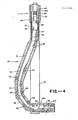
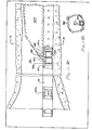
- FIG 1 schematically shows an earth well 10 which extends down to the mineral bearing formation 12.
- the well is shown provided with a casing 14 which may extend down to an underreamed cavity 16 that is adjacent to the formation 12.
- Structure 17 includes piping extending in the well consisting, in this instance, of outer piping 18 in the form of a pipe string with a lowermost section 18a shown in Figure 2, within which a drilling tube 20 is normally disposed.
- a seal 22 is mounted within the pipe string and forms a seal between the pipe string and drilling tube 20. The upper end of the drill pipe is above seal 22 when the drilling tube is retracted. Before the drilling tube is extended, it is within pipe string 18 with its drilling head 24 located below seal 22.
- Structure 17 also includes housing 26 serving to carry whipstock means 28.
- FIG. 1 also schematically shows a production rig 30 of the mobile type and a reel carrying truck 32 which may carry a supply of drilling tube 20, which brings supply drilling tube for use in the well but is not connected during placement of the drilling tube.
- housing 26 carries five bending assemblies 30, 32, 34, 36 and 38 pivotally connected at hinges.
- Housing 26 contains the whipstock means in a deerected position, anchor means and means for erecting and deerecting the whipstock means as described hereinafter.
- Outer piping 18 includes clearance for the whipstock means to be erected. As illustrated in Figures 1, 3 and 4 clearance is to the left and right of the whipstock.
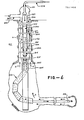
- housing 26 is in the form of flat rigid side plates 40 interconnected at the bottom by lift pin 42 and at the top by bolts 44 mounted to the interior piping and assemblies as described below.
- Lift pin 42 is pivotally connected to the most forward whipstock segment 38.
- housing 26 is lowered into casing 14 until it reaches the desired position adjacent to formation 12. All components of this system are contained within the structure during such passage in a manner that permits the system to be lowered through a preexisting casing.
- anchor means 46 is illustrated in a retracted position within the casing with the whipstock means deerected.
- Anchor means 46 is operatively connected to the rearward side of whipstock means 28. In the illustrated retracted position, it slides within the earth well. In the anchored position illustrated in Figure 3, it locks in a fixed position relative to the earth well and causes the whipstock means 28 to raise from the fixed anchor position and thus, lift pin 42 can be raised during erection as described below.
- Inner piping 48 is mounted in outer piping 18 and, in combination with other portions of structure 17 serves to anchor, erect and deerect whipstock means 28.
- Inner piping 48 is threadedly connected at its forward end or lowermost segment the top segment 30 of whipstock means 28.
- the system also includes deerection means comprising an upper deerection spring 52 and a lower deerection spring 54.
- Upper deerection spring retainer 56 is mounted to inner piping 48 and includes a lower shoulder 56a for retaining spring 52.
- An erection sliding seam 58 is mounted to the interior of inner piping 48 to maintain a seal with the drilling tube when the system is erected as described below.
- a lower spring retaining ring 60 is mounted to outer piping 18.
- an upper spring retaining ring 62 is mounted to inner piping 48 while a lower spring retaining ring 64 is mounted to outer piping 18.
- Springs 52 and 54 provide the same kind of compressive forces for erection and deerection of the system as described below. They function in a similar manner and are additive in their compressive forces. If desired, a single spring could be utilized with the desired amount of force.
- Anchor means 46 is the only portion of the illustrated apparatus that is not fixidly secured to either outer piping 18 or inner piping 48.
- Components of anchor means 46 are drag springs 66 slidably carried by inner piping 48 and projects through slot 67 in outer piping 18 to ride against casing 14 while the assembly is being lowered into position. Drag springs 66 serve to center the overall unit and to provide sufficient frictional force against casing 14 to permit the anchor to lock into position against it when outer piping 18 is pulled upwardly as described below.
- Anchor means 46 also includes anchor jaws 68 with a saw tooth-like outer surface 68a for embedding into casing 14 when urged outwardly as set out below.
- the interior surface of anchor jaws 68 are sloping walls 68b which slope inwardly in an upward direction to provide a surface against which a correspondingly sloped ramp may act.
- Jaws 68 are slidably mounted to ride on inner piping 48 and are spring mounted so that they are urged inwardly unless actuated.
- anchor jaws 68 When the system is lowered to the desired elevation adjacent the formation in the position illustrated in Figure 2, anchor jaws 68 are out of registry with vertical slot 67 and so are retained within outer piping 18 by abutting against the adjacent wall of that structure.
- Such anchor jaws are the same elevation as the vertical slots so that when it is desired to anchor the system, outer piping 18 is rotated relative to inner piping 48 causing the anchor jaws to move into registry with such slots whereby they are urged outwardly
- a jaw extension ramp 70 is mounted to outer piping 18 including a sloped upper wall 70a of a shape which mates with the inner sloping wall 68b of anchor jaws 68 to cause the anchor jaws to be urged outwardly when ramp 70 is moved upwardly relative to the jaws.
- anchor means 46 is as follows. When the desired elevation adjacent to the formation is reached, the outer piping 18 is rotated relative to inner piping 48 to permit anchor jaws 68 to move into registry through their corresponding slots. The slots extend a sufficient distance below jaws 68 to permit upward movement of outer piping 18 to erect the system as described below. Structure 17 is pulled by an extension arm 72 which may comprise a pipe which extends all the way to the surface. Extension arm 72 includes a passage through which the drilling tube projects as described below. Then extension member 72 is pulled upwardly, both the outer piping 18 and inner piping 48 are correspondingly pulled because they are connected at lifting pin 42.
- drag spring 66 provides sufficient resistance against upward movement that anchor jaws 68 begin to be locked into an embedded position in the casing wall when urged against the wall by jaw extension ramp 70 as the inner piping is pulled upwardly. Outer piping 18 is not affected because of the slot clearance.
- whipstock means 28 begins to erect because lift pin 42 is being moved upwardly while the top segment 30 of whipstock means 28 is being retained in a fixed elevational position by anchor means 46. Since guideway assembly 38 is pivotally mounted to lifting pin 42 and because lifting pin 42 is mounted eccentrically (towards the left hand side as illustrated) segment 38 begins to pivot to the left until the sloping upper wall 38a contacts the corresponding lower wall 36a of guideway assembly 36. Such pivoting begins at the bottom rather than the top because the lower piping segment 18a forms a shroud which maintains upper guideway assembly 30 in a fixed position during the initial erection. This permits the system to be erected into the desired configuration. Thereafter, after erection is begun, piping segment 18a clears upper guideway assembly 30 to permit it to be erected as illustrated in Figure 3.
- Springs 52 and 54 are partially compressed prior to lowering of the system into the earth well. This serves to maintain whipstock means 28 in a straight line deerected configuration within side plates 40 for passage through the earth well be keeping the whipstock in tension.
- upward retaining rings 56 and 62 being mounted to inner piping 48 are in a fixed elevational position while lower retaining rings 60 and 64, being mounted to outer piping 18 move upwardly to cause springs 52 and 54 to be further compressed. This assists in deerecting the system as described below.
- Such additional compression also stiffens the system which applies a strain load on the whipstock means to strengthen the hinges in the erected position.
- Whipstock means 28 may be maintained in an erected position by insertion of a slip collar at the surface. When deerection is to be accomplished, the slip collar (not shown) is removed to permit the outer structure to move downwardly.
- a detailed view of the erected whipstock is illustrated.
- a high pressure seal which provides piston-like forces to push the piping through the whipstock and into the formation in the manner described with respect to U.S. patent 4,527,639, incorporated herein by reference.
- high pressure fluid is directed against a fluid pressure bearing area to the rearward side of the drillhead which is of the hydraulic jet type, including one or more jet type openings.
- the pressurized drilling fluid presses against the seal and the portion of the guide pipe upstream from he seal so that the force is directed against the rearward side of the drill head causing it to project in a forward direction.
- Whipstock means 28 functions as follows: Above seal 22 is a guide ring 80 which guides drilling tube 20 through the seal 22 and allows water to enter a bypass system whereby water can be used to flush the small annulus between the interior guide walls of the whipstock and the drilling tube. Prior to application of the hydraulic forces, the drilling tube is placed into the seal. Then, the system is pressurized so that drilling tube 20 moves past the first two wheels 82 in the system. Then, the drilling tube causes a bending action toward the backside of the whipstock means and loads the third wheel 86 in guideway assembly 30.
- the drilling tube now enters guideway assembly 32 and is guided by the first two wheels 88 causing the drilling tube to be guided along the ramp of that section until it hits the last ramp 90 just above the last wheel 92 to force the drilling tube to load onto wheel 94 and start the bending motion of the drilling tube toward the right hand side of the drawing.
- Wheels 92 and 94 provide the initial bending of the drilling tube into about a one foot radius which allows it to move through guideway assemblies 34 and 36 without substantial additional bending moments.
- Wheels 98 in guideway assembly 34 and wheels 100 in guideway assembly 36 act as guide wheels to position drilling tube 20 relative to guideway assembly 38 which serves as a straightener.
- the ramps in guideway assemblies 34 and 36 assist in loading the drilling tube 20 onto such wheels if the bending is not sufficiently precise.
- As drilling tube 20 exits guideway assembly 36 it is guided by the wheels in that segment to cause the drillhead to contact the ramp at the bottom of guideway assembly 38 which loads the drillhead onto straightener wheel 102 mounted in carriage 104 which forces the drillhead to the top of segment 38 and causes it to move into the formation in a straight line.
- Carriage 104 is adjustable so that by calibration, the position of wheel 102 may be set so that the drillhead proceeds horizontally into the formation or at any desired angle.
- whipstock means 28 projects to both sides of the housing and so less underreaming is required than if it projected only to one side.
- the whipstock means assumes an inverted comma shape with the drillhead turning at a relatively sharp angle just prior to moving into the formation. Underreaming may be accomplished in a conventional manner.
- Another advantage of the internal mechanism of the whipstock means is that due to the unique use of rollers and slides, the friction is low, the drillhead can make the initial turn without damage and the drilling tube is maintained in a relatively round configuration during the turning.
- the use of the wheels and ramps permits this to be accomplished with minimum flattening of the system.
- a significant advantage of the present system is that the whipstock means is erected by the simple mechanical force of pulling from the surface rather than by the use of a hydraulic cylinder to cause erection.
- One advantage of such erection is the precise knowledge that the whipstock means is fully erected to permit the radial to move horizontally into the formation. This is known because when the outer structure is pulled upwardly at the surface a predetermined distance for full erection, the whipstock is erected. This is to be contrasted with hydraulic cylinders which are not as precise in their operation due to leaks and the like. Also, since there is a continuous string to the surface, pipe stretch does not affect the function of erection.
- the system of the present invention is also capable of ready deerection to either move structure 17 to another portion of the same earth well or to pull it totally out of the earth well for reuse in another earth well.
- deerection is accomplished by releasing the anchor means from the casing, causing the inner piping to move downwardly relative to the outer structure and thereby moving lifting pin downwardly to pull the segments of the whipstock into a straight line as illustrated in Figure 2.
- Springs 52 and 54 are maintained under sufficient compression so that even during deerection, the segments of the whipstock means are maintained under tension to prevent spontaneous erection of the system.
- the outer structure is moved downwardly causing lift pin 42 to move correspondingly downwardly and to move the whipstock means into a straight line or retracted position.
- the whipstock means in a straight line
- continued lowering of the outer structure 26 causes inner piping 48 to be pulled downwardly at lift pin 42 and thereby causing ramp 70 to move downwardly out of engagement with the corresponding inner walls of 68b of jaws 68.
- jaws 68 collapse against inner piping 48.
- outer structure 26 is rotated relative to jaws 68 to cause the jaws to move out of registry with the corresponding slot and to be thereby retained in a retracted position by adjacent wall segments of the outer structure.
- the jaws 68 prevented from locking against the inner wall of casing 14, the entire unit may be lifted up out of the earth well.
- jaw extension ramp 70 is mounted to inner piping 48 by shear pin 110. If the jaws will not release in a manner set out above, sufficient pushing force is applied from the surface against structure 17 to shear the shear pins and cause ramp 70 to fall out of engagement with jaws 68.
- support spring 112 is provided below the ramp 70 which is sealed by upper and lower wiper rings 114 and 116 respectively against sand from moving into the system. In this manner, when shear pins 110 are sheared, ramp 70 may fall a sufficient distance to release jaws 68 due to the clearance provided by spring 112.
- sliding seal 58 is mounted to the outer piping 18 to provide a high pressure hydraulic seal to prevent any gap during relative movement of the outer piping and inner piping.
- a radical is placed in the desired mineral bearing formation, typically in an oil field.
- the surrounding formation may be heated as by injection of steam and oil is caused to flow either back to the same well or towards another production well.
- the drilling tube portion projecting into the formation is severed near the whipstock by conventional means.
- the drilling tube is first removed from the whipstock section by pulling upwardly from the surface. This, of course, is facilitated by first severing the portion of the drilling pipe projecting into the formation. Thereafter, deerection is accomplished as set forth above.
- the above system is particularly effective when used in conjunction with a drilling pipe propelled by hydraulic forces as set forth in above.
- hydraulic seals are provided in this system to accomplish the piston-like effect.
- the system may also be employed to move a radial pipe into the formation by some other means.
- the present invention comprises an improvement over the hydraulic piston-effect method and apparatus of U.S. patent 4,527,639. That application describes a system in which hydraulic forces are applied against a drillhead to pull a pipe into the formation. The present system adds to that pulling force a pushing force from the other end of the drill pipe.
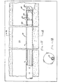
- a drill string 214 is formed of a metal tube of the solid wall type which may, for example, have an outer diameter (OD) of approximately 1.25 in. and of a character which may be coiled on a spool and passed downwardly into the system prior to sealing the system into the form shown in Figure 5.
- OD outer diameter
- the string is severed and lowered down the guide pipe.
- Drill string encompasses a single unitary hollow pipe of the type which may be used for radial hollow tube section 214a or multiple sections connected together, some of which may not be hollow, such as a sucker rod with threaded attachments to each end to provide dead weight as described in embodiments set forth hereinafter.
- Drill string 214 is typically in the form of a hollow pipe and defines an interior passageway 214b which extends from drillhead 216 upstream in the system to multiple ports 214c for reasons described below. Upstream of ports 214c may comprise a hollow or solid pipe so long as the interior passageway is sealed towards the top of the drill string.
- drill string 214 comprises a pipe connected at its forward end to drillhead means 216 of the hydraulic jet type including multiple ports 216a through which the drilling fluid exits to bear against and erode the formation in its path.
- a removable cap 218 is secured into the other end of drill string 214. The purpose for the cap is to seal the interior of drill string 214 at the location of the cap. The cap may be removed periodically to permit the lowering of a wire line tool through the system to determine the position of the drillhead 216 at any point in time.
- the system operates within a pre-existing cemented-in well casing 219 in which outer piping 220 is mounted leaving an annular chamber 221 therebetween suitable for the passage of cuttings from the drillhead as described below.
- Outer piping 220 is sealed at its lower end to a guide pipe 222 including interior rollers 224.
- Guide pipe 222 is in turn connected to whipstock means 226 which includes four segments 226a, 226b, 226c, 226d and 226e in an inverted comma position.
- Drill string 214 moves through rollers 224 and whipstock means 226 to turn from a generally vertical direction to a generally horizontal direction forming radial 214a.
- Whipstock means 226 is lowered into the formation in a collapsed position and is formed in situ into a whipstock of the illustrated shape in the manner described above.
- Means 227 defining a driving fluid chamber 228 is provided in the form of cylindrical inner piping 230 which is sealed from the annular space surrounding the same.
- a first sliding seal 232 is mounted to the inner wall of inner piping 230 through which drill string 214 slides.
- Inner piping 230 is surrounded by outer piping 220.
- Outer piping 220 and inner piping 230 at least partially define drilling fluid chamber 234 which is sealed from driving fluid chamber 228.
- Means is provided for forming a seal between drilling fluid chamber 234 and drill string 214 in the form of a second seal 235 mounted to guide pipe 222 through which drill string 214 passes.
- Means (not shown) is provided for supplying hydraulic fluid to driving fluid chamber 228 and drilling fluid chamber 234. As illustrated, the fluid moves through conduit 236 in which the major portion of the fluid is passed. A portion of the drilling fluid in conduit 236 may be bled off by valve means 238 into conduit 240 for passage into stationary driving fluid chamber 228. Conduit 240 passes through a sealed aperture 241, in a domed sealed top 220a mounted to outer piping 220. In an alternative embodiment illustrated in Figure 6, a separate source of driving fluid may be employed.
- the drill string 214 passes through whipstock means 226 and becomes a radial or lateral tube or duct 214a suitable for the injection of hot fluids such as steam into the formation to heat up the viscous oil for removal.
- hot fluids such as steam into the formation
- heat from the hot fluid causes the oil to flow back towards the casing containing a production pump as well as a radial.
- the general principal of forming a radial in accordance with the present invention uses (a) a hydraulic pulling force applied by urging fluid against the drillhead means 16 which thereby pulls the radial into the formation from the downstream end of the drill string in combination with (a) a hydraulic driving or pushing force applied in driving fluid chamber 228 against the upstream end of the drill string.
- the former type of force is generally described in U.S. patent 4,527,639.
- drill string 214 is adapted to move through seals 232 and 235, through whipstock means 226, and into the formation.
- An open passageway is provided from conduit 236 through drilling fluid chamber 234, ports 214c, into the interior fluid passageway 214b and forward to the rearward side of drillhead means 216.
- the fluid exits through multiple fluid exit ports provided in the drillhead means for the passage of the drilling fluid into the adjacent formation.
- High pressure fluid flowing from drilling fluid chamber 234 applies pressure against the rearward side of the drillhead to cause drill string 214 to move in a forward direction.
- the only portion of the drill string which passes through whipstock 226 comprises a hollow tube in the form of a radial which is stressed and deformed plastically in a physical metallurgical sense to bend and turn into the radial, preferivelyably in a horizontal direction, so as to be moved into the formation.
- the high pressure liquid issuing from the drillhead drills out the formation and forms cuttings which are slurrified and passed backwardly along the outer periphery of drill string 214 as illustrated by arrows A on Figure 5 for movement outside the outer piping 220 to the surface.
- the drilling fluid pressure is greater than the formation pressure, the fluid may be directed into the surrounding formation under such force that the formation fracs or fractures, causing fissures into which the formed slurry can flow, whereby little, if any, cuttings are moved rearwardly along the radial and so lifting of such cuttings is not required.
- the system also includes a pushing force by fluid being passed through conduit 240 into driving fluid chamber 228 and applies against cap 218 at the top of the drill string.
- the location of driving fluid chamber 228 and drilling fluid chamber 234 may be at the top of the drill string or at some point below that so long as seal 232 is above whipstock means 226.
- a long length of tubular pipe may be eliminated and replaced with a rod since the portion of drill string 214 above ports 214c need not be an open passageway.
- One advantage of this system is that it is capable of drilling radial bores with a non-rotating drill string, and that the bore hole may be cased while drilling.
- the system may be installed as follows: A preexisting well casing placed in the surrounding formation in the vicinity of the whipstock may be underreamed by a conventional means.
- the whipstock may be lowered into the predetermined position by use of a string system formed of segments with threaded attachments on adjacent segments. It may remain in place and form the portion of the drill string terminating at cap 218, above ports 214c. Such ports maintain open communication between the interior passageway and the fluid in drilling fluid chamber 234 during movement of the radial through the whipstock and to the desired final position in the formation.
- This string, or a tubing string separately placed may remain in place forming a dead weight to provide additional pushing force against the drill string.
- the string may be removed so long as there is sufficient drill string extending upwardly so that a portion extends through seal 232 from the time of driving the drill string forward through the whipstock through the ultimate placement of the radial.
- the system can be sealed as by putting top 220a on the casing to seal the top of driving fluid cylinder means 228.
- a number of systems can be employed for determining the position of the radial in the formation.
- a reel with a line attached to the top of the drill string may be employed so long as there is access to the reel at the surface.
- an acoustical assembly may be used with a transmitted signal emitting from the drillhead which reflects back to give a measured transit time and movement.
- Another system would be to measure distance as a function of the displacement of fluid flowing into the driving fluid chamber. However, if the tubing joints are not completely tight, leakage may occur which could cause an error.
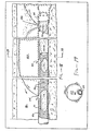
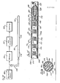
- FIG. 6 another embodiment of the invention is illustrated with a different form of driving mechanism but the the remainder of the apparatus the same.
- Like parts will be designated with like numbers in the two systems and the description with respect to such like parts in Figure 5 will apply to the system of Figure 6.
- a piston body 250 is attached to the upstream side of drill string 214 of a cylindrical shape and having a cross-sectional area which may be substantially larger (e.g., 1.1 to 10 times, preferably 2 to 4 times larger) than the cross-sectional area of the drill string, in the plane perpendicular to the direction of movement of the piston body. It includes a removable plug 252 mounted at its top which can be removed to install a wireline device in the drill string in an analogous manner to that of plug 218.
- a third high pressure seal 254 is mounted to the exterior wall of piston body 250 in close sealing engagement with the cylindrical side wall of inner piping 230. (Alternatively, seal 254 may be mounted to the interior wall of inner piping 230).
- Means is provided for bleeding off fluid in the chamber formed below piston body 250 and above first seal 232.
- Such means is in the form of ports 256 which direct the fluid to the outside of outer piping 220 without contacting or restricting the flow of fluid in chamber 234 when piston body 250 is actuated by driving fluid supplied by conduit 258 to driving fluid chamber 228.
- Drilling fluid is supplied by conduit 260 to drilling fluid chamber 234.
- independent sources of fluid are provided for the two chambers.
- Piston body 250 is sufficiently long so that it maintains a seal with seal 254 when a corresponding length of drill string is moved by the hydraulic forces through whipstock 226 and out the radial to the desired distance.
- the use of an enlarged cross-sectional area for the piston body permits a multiplication of the driving force supplied by the system.
- a doubling of the cross-sectional area leads to a corresponding doubling of the force which is applied to the top of the drill string when the remainder of the parameters are maintained constant.
- the amount of force applied against the top of piston body 250 is also controlled by the pressure of the fluid supplied by conduit 258 to driving fluid chamber 234. In this manner, a close control of the system may be maintained by varying the pressure of such driving fluid in line 258.
- control may be further augmented by the use of a restraint such as a cable (not shown) which is operatively associated with the drill string such as by connection to the drill string near the top of it which controls the maximum rate of movement of the system.
- a restraint such as a cable (not shown) which is operatively associated with the drill string such as by connection to the drill string near the top of it which controls the maximum rate of movement of the system.
- the rate of movement can be controlled by a corresponding variance in the fluid applied in line 258 without the requirement of the cable restraint.
- seal 232 has a cross-sectional area substantially larger (e.g., 1.1 to 10 times, preferably 2-104 times larger) than the cross-sectional area of seal 235.
- the cross-section of that portion of drill string 214 which passes through seal 232 during drilling is correspondingly enlarged without enlarging the cross-section which passes through seal 235.
- Rod 214d provides a dead weight driving force to the drillhead which is additive to the hydraulic forces described above.
- Rod 214d is suitably in the form of a threaded rod which may be threaded at connection 214e to the remainder of drill string 214.
- the dimensional constraints of rod 214d are that it be long enough to maintain a seal with seal 232 during the application of hydraulic forces and that they extend to the position no further along the drill string than a point upstream of ports 214c.
- an interior passageway is formed which communicates with the drillhead 216.
- FIG 8 another embodiment of the invention is illustrated which is similar to that of Figure 6. Like parts in Figure 8 will be designated with like numbers of Figure 6.
- the difference between Figure 6 and Figure 8 is in the area of the drill string above ports 214c.
- a solid metal rod portion 262 interconnects the bottom of piston body 250 and the area of drill string above ports 214c.
- Such rod 262 constitutes, in essence, a piston rod in the form of a sucker rod with screw threaded connections to both the piston body and top of the drill string.
- One advantage of this interconnection is that it provides the additional dead weight to drive the drill head described with respect to Figure 7.
- FIG 9 an embodiment of the invention is illustrated similar to that of Figure 6.
- a continuous hollow pipe drill string 214 is illustrated as in Figure 6.
- the major difference in the two embodiments is the inclusion of a weighted drill collar 264 mounted to the drill string at a point below seal 232 and above ports 214c.
- the advantage of this location is that the drill collar need not pass through any seals.
- the dead weight may be also added at some other point in the system so long as it does not interfere with any of the seals.
- Drillhead 216 may be of any type which provides a rearward surface against which the force of the drilling fluid has directed and which provides ports through which the drilling fluid may exit, preferably in a direction axially aligned with the horizontal drilling path of the radial hole, together with other ports in other directions, if desired.
- Suitable drillheads for use in accordance with the present invention are described in U.S. Patent 4,527,639.
- Another advantage resides in the separation of the fluid applying hydraulic forces in isolated driving fluid chamber 228 and drilling fluid chamber 234 because the required fluid pressure in the former chamber, being isolated from the large volume drilling fluid in the latter chamber, provides a precise measure of the resistance to movement of the drillhead. It has been found that when this pressure exceeds a predetermined level, the system may have become irreversibly stuck embedded in a resistant area of the formation if drilling continues. By monitoring the driving fluid pressure, when this level is exceeded, the drill string may be withdrawn a short distance and the hole redrilled, resulting in avoidance of the sticking problem.
- piston body 250 includes a hollow lumen and an open top 250a so that the fluid passes through from the open top through the lumen of drill string 214 and out ports 216a of drillhead 216.
- the enlarged seal 254 relative to seal 232 provides a force multiplication to the system.
- parts 214c and seal 235 are eliminated because all fluid provided to the system passes through the open top of piston body 250.
- a particularly effective system for placing radial tube 20 is by use of the assembly of Figures 1-4.
- the drill string forms a piston sliding in a guide tube. Pressurized fluid flowing through the piston body applies pressure against the drillhead causing it to move into the formation at the same time as it is cutting a pathway for itself.
- a system of this type is described in U.S. patent 4,527,639. A modification of this system is described above.
- radial tube 20 passes through whipstock 28.
- Drilling fluid passes through the ports of drillhead 24 creating an annulus 42 between radial tube 20 and the surrounding formation.
- a feature of the invention is to provide an effective means of gravel packing of annulus 42.
- Gravel packing constitutes the placement of particles in an oil permeable porous mass or jacket (termed “gravel pack”) in a zone, such as annulus 42.
- the gravel pack passes oil while filtering out most of the particles in the surrounding formation.
- Such gravel typically in a sieve size range of 6 to 40, is placed by passage to the desired area in a slurry form and compacted in that area. For example, it is well known to pack underreamed area 16 with gravel pack particles.
- gravel packing is accomplished by flowing the slurry of particles, of approximate size to form gravel pack, from within the well bore through the lumen of radial tube 20 and out openings in the distal end of the tube into annulus 42 and back toward the well bore to form a jacket of gravel pack in the annulus.
- water may be flowed through the radial tube at a pressure and for a time sufficient to remove the particles from the radial tube lumen.
- the radial tube is perforated after placement in the formation.
- the radial tube is perforated with multiple openings disposed toward the distal end through which the gravel pack slurry is flowed.
- additional perforations are also formed at spaced intervals along the remaining length of radial tube 20.
- Perforation may be accomplished electrolytically by use of a perforating tool 344 which is functional in combination with an electrically conductive radial tube 20.
- the tool includes an elongate hollow perforating tube portion 346 terminating at its forward end in a nose portion 348 including circumferentially spaced electrically conductive nose port walls 350 defining about 8 to 16 outer diameter ports 350a extending through hollow nose portion 348.
- Nose portion 348 is formed of an electrically insulative material which insulates port walls 350 from each other.
- such port walls are electrically connected to a source of power, suitably through an electrically conductive connector 352 which in turn is electrically connected to a conductor embedded in tube portion 346 which then connects to the power source.
- Tube port walls 355 are electrically conductive cylinders projecting through the tube portion walls and electrically connected through flexible metal sheath 358 which extends from connector 352 to the source of power.
- Metal sheath 358 is insulted by outer electrically insulted jacket 360 and inner electrically insulted jacket 362.
- Tube portion 346 is sufficiently flexible to pass through the turn of whipstock means 336.
- an appropriate electrolyte such as an aqueous solution of potassium chloride
- an appropriate electrolyte is passed from the surface through the interior of the tube portion 346 and the hollow nose portion 348, and ports 350a to contact the portions of the electrically conductive radial tube 338 adjacent such ports.
- perforations are formed in the region adjacent to ports 350a of a size sufficient to pass gravel pack particles.
- a suitable rear connector assembly 364 for accomplishing this objective is illustrated in Figure 13.
- Assembly 364 includes a hollow metal tube 366 electrically connected by adaptor 368 to metal sheath 358.
- tube 366 At the other end of tube 366 is means providing entry of the electrolyte into the tube and for passing of current to it.
- such means comprises electrically conductive spaced bars 370.
- Another electrically conductive adaptor 372 interconnects the rearward side of bars 370 and electrical cable 374 which extends to the source of electrical power.
- a flexible seal 376 is provided around tube 366 to block the passage of electrolyte in the annulus between tube 366 and radial tube 338 so that the fluid is directed through bars 370 to the inside of tool 346. In this manner, electrolyte passes through ports 350a and 355a in a concentrated stream to provide a precise area of electrolyte contact during formation of the perforations.
- the elongate hollow perforating 344 is passed through radial tube 20 until its forward end is adjacent that end. Then, the electrolyte solution is passed through the lumen of the perforating tool and out ports 350a to be directed against adjacent regions of the electrically conductive radial tube while current is supplied to the port walls 350 to form spaced perforations at the adjacent regions of the radial tube. Thereafter, the perforating tool is withdrawn.
- perforations are also formed at spaced intervals along the length of the radial tube by including the aforementioned port walls 355 and passing the electrolyte through the ports 355a to perforate the radial tube 20 in a similar manner to the perforations formed at the distal end.
- an electrolytic pipe cutting device 380 is illustrated connected to an electric cable 382 which, in turn, is connected to the source of electrical power, not shown.
- Device 382 includes a nose cone 384 suitably formed of an impact resistant material such as nylon and an electrically conductive metal strip 386 electrically connected to cable 382.
- Cutting device 380 also includes ceramic rings 388 on both sides of metal strip 386 serving as heat sinks to remove heat generated at strip 386 during cutting.
- Cutting device 380 also includes forward and rearward liquid channeling sections 390 and 392, respectively, with channels 390a and 392a respectively, serving to channel the flow of liquid passing ring 386.
- the cutting device of Figure 15 is pushed to a predetermined area of radial pipe 20 and an aqueous electrolytic solution, such as of potassium chloride, is pumped passed the cutting device 380 and out drillhead ports 350a.
- an aqueous electrolytic solution such as of potassium chloride
- the cutting device 380 is directed to the drillhead until nose portion 384 abuts the rearward side of the drillhead to position strip 386.
- the electrolyte is directed passed strip 386 while a DC power source energizes the strip.
- An electrical circuit is completed between strip 386 and the adjacent wall of radial tube 20 and the radial tube is severed.
- pipe cutting device 380 is pulled out of radial tube 20.
- a suitable permeable filter device is placed proximal to the opening formed at the severed distal end of radial tube 20 of a type which blocks flow of formation particles into radial tube 20 while permitting the flow of oil. This may be accomplished simultaneously by use of a pipe cutting filter device assembly as shown in Figure 17.
- radial tube 20 is severed at its proximal end. Then, the main drill string is pulled out of the well and the whipstock is repositioned at a desired location. For example, the whipstock may be left at the same elevation and rotated to a different radial position. Thereafter, another drill string is passed through the whipstock in the manner described above to form spokes projecting from the well axis.
- a cutting device 380 is positioned near the distal end of radial tube 20.
- the pipe is severed by passing current through the device while simultaneously flowing an electrolytic solution by it as described above.
- One way to precisely position the cutting device is to include a rigid bar as a portion of the flexible cable of a length such that it cannot make the full turn through the whipstock.
- the cutting device is positioned at a predetermined distance downstream from the rigid pipe so that it is near the distal end of radial tube 20.
- cutting device 380 may be pulled to the surface through cable 382. Alternatively, it may be left in place by providing an automatic detachment such as an electric fuse device at the cable connection so that the cutter remains in place while the cable is pulled to the surface. This embodiment is more fully described with respect to Figure 17.
- Plug filter portion 398 is constructed to be capable of substantially blocking gravel pack particle flow while passing fluids such as oil. As illustrated, it comprises a bottle brush-like permeable plug including a spine 402 and wire brushes 404 projecting radially from its axis 402 which is mounted to the adjacent portion of pipe cutting portion 400. Further filtration means such as steel wool may be placed between turns of the wire brushes 404 to enhance filtering.
- Pipe cutting portion 400 including metal strip 397, may be constructed in the same manner as pipe cutting device 386 and interconnected to a suitable source of power through cable 406.
- Suitable detachment means may be provided between cutting device portion 400 and plug filter means 398 for detachment after severing of pipe 20 adjacent metal strip 397.
- Such detachment means may comprise an electric fuse or a detachable threaded connection or the like. After severing near the proximal end of radial tube 20, cutting device portion 400 may be withdrawn followed by a removal of the main drill string to permit deerection of the whipstock.
- Plug filter means portion 398 serves to maintain the interior of radial tube 20 essentially free of gravel pack or formation particles to permit the oil to accumulate efficiently in the radial tube.
- plug filter means may be placed at both the distal and proximal ends of the radial tube in combination with a liner as described hereinafter.
- plug filter means may be placed at the distal and proximal ends of radial tube 20 without the use of a liner so that the oil flows into the radial tube only through the plug filter means, and thereafter through the gravel pack into the underreamed cavity 16 for pumping to the surface in accordance with conventional technology.
- a radial tube 20 is illustrated in the formation of a porous, elongate, hollow tube liner 410 defining lumen 410a coaxially disposed within the radial tube.
- Radial tube 20 includes drillhead 24 with ports 24a and circumferentially spaced ports 412 disposed close to the drillhead. Ports 412 serve to permit the flow of gravel pack particles through lumen 410a of liner 410 during gravel packing.
- Radial tube 20 also includes ports 414 spaced longitudinally along the radial tube.
- Liner 410 is sufficiently flexible so that it may be passed through the curve of whipstock means 28 without undue friction.
- Liner 410 is also sufficiently permeable to liquid so that a portion of the water content of the slurry passing through lumen of 410a of liner 410 passes out ports 24a into annulus 42.
- a suitable form of liner 410 to accomplish these objectives is conventional BX electrical conduit for electrical cable, typically formed of a metal spiral wound in a coil with spaces between adjacent coil segments. If desired to increase fluid porosity, additional ports such as slits 416 may be provided in the liner.
- slotted liner 410 is placed prior to placing radial tube 20, the formation adjacent the whipstock is underreamed and the whipstock is erected. Then, slotted liner 410 is placed.
- a flexible piston may be placed on its nose, formed of a material such as Velcro, so that it can be pumped down by passing fluid in the annulus between liner 410 and radial tube 20.
- liner 410 can be pushed down either by radial tubing and by an internal stiffener rod to provide sufficient rigidity to prevent collapse of the liner during placement. After placement, the internal stiffener rod is removed. In either event, liner 410 is placed until the forward end abuts the rearward side of the drillhead.
- ports 412 are approximately twice the cross-sectional area of radial tube 20. This large area minimizes the pressure drop through the ports and thus the slurry velocity to avoid entrainment of the gravel pack in the formation.
- the gravel flowing out ports 412 at such lower velocity than during drilling flows towards the well bore and forms a dune 417 because the gravel flow is below the slurrification velocity.
- the moving sand dune 417 fills up a portion of the annulus 42 and leaves an open area, referred to as an ullage 418, which is segment shaped with a relatively flat bottom and curved top.
- the face of the sand dune 417 gradually moves to fill up annulus 42 in the range of about 50-90% of the total cross-section of the annulus.
- FIG. 18 shows the sand dune 417 in transit prior to reaching the well bore.
- sensing means 420 is disposed intermediate forward segment 410a and rearward segment 410 near the proximal end of radial tube 20.
- Sensing means 420 serves to detect the presence of gravel pack by a drop in conductivity which occurs when the gravel pack contacts it.
- sensing means 420 includes an electrically insulating housing 424 which contains axially spaced electrodes 426, 428 and 430. Electrode 428 is oppositely charged to electrodes 426 and 430, one of which is redundant.
- the electrical conductivity of the medium disposed between the two oppositely charged electrodes is monitored. Such medium constitutes the liquid of slurry flowing from annulus 42 through ports in radial tube 20 to contact the electrodes.
- the drop in conductivity caused by the sand dune 417 contacting it is sensed and, in response, gravel flow is discontinued.
- plug filter means are placed at both ends of radial tube 20 and the tube distal end is severed from the remaining portion of the drilling string, so that the whipstock may be deerectd and additional radial tubes placed into the formation in the same manner.
- a slotted liner may be placed down the well bore and gravel pack pumped around the liner to fill the underreamed area 16 and to backfill any remaining void areas in the annulus which have not been previously filled by the sand dune gravel pack jacket.
- the radial tube 20 is of the same type as illustrated in Figure 18 with like parts denoting like numbers and with a severed proximal end 20.
- the system includes a liner 410 of the aforementioned type disposed within the radial tube.
- Permeable plug filter means 432 and 434 are placed at the proximal and distal ends, respectively, of the radial tube in the manner described above.
- Pipe cutting device 380 may also be used to sever the portion of liner 410 disposed between device 380 pipe and radial tube 20.
- Additional gravel pack 436 is placed in a conventional manner using a slotted liner in the well by pumping through the well and the underreamed portion and continuing pumping until the remainder of the annulus is filled.
- the radial tube of Figures 22 and 23 is now fully gravel packed and in combination with the conventional well bore is suitable for production. Oil from the surrounding formation flows through radial tube perforations 414 and permeable liner 410 into lumen 410a of the radial tube and from there into a sump at the well bore for pumping to the surface in accordance with conventional technology.
- multiple radials are placed and disposed in the manner of spokes projecting from an axis.
- a curvature probe useful for locating the drillhead, has an elongated body 511 of generally circular cross-section.
- a roll sensor 512 is mounted in the forward section of the body, a curvature sensor 513 is mounted in the central section, and electronic circuitry 514 for processing signals from the roll sensor and the curvature sensor is mounted in the rear section of the body.
- the roll sensor is of suitable known design, and it provides an output signal corresponding to the orientation of the probe about its longitudinal axis.
- the roll sensor utilizes a gravitational reference, and the output signal from this device indicates the orientation of the probe relative to the downward direction, i.e. toward the center of the earth.
- the length of the probe is substantially longer than the diameter, and the outer diameter of the probe is slightly less than the diameter of hole to be logged.
- the probe has a diameter of the order 3/4 of an inch, and the central section in which the curvature sensor is located has a length on the order of 18 inches.
- the curvature sensor has an axially extending flexible shaft 516 positioned centrally within the probe body.
- the flexible shaft is freely bendable about its axis, but it is torsionally rigid, i.e. it does not twist about its axis when rotated.
- the shaft comprises a double-woven cable which is substantially neutral and has no bias which favors or resists flexing in a particular direction. This type of cable is commonly employed for control drives.
- a plurality of guide members or spacers 517 are mounted on shaft 516.
- Each of the members comprises a generally annular body having a central opening 518 through which the flexible shaft extends.
- openings 518 are of slightly larger diameter than shaft 516 so that the guide members are free to move in the axial direction on the shaft.
- Each of the guide members has an outer peripheral surface 519 with a contour corresponding to the cross-sectional contour of the opening in which the probe is used.
- the guide members are preferably fabricated of a rigid material such as nylon, but they can be fabricated of any suitable material.
- Means is provided for maintaining the guide members at an axially spaced relationship on the flexible shaft.
- This means includes compression springs 521 which are positioned coaxially about the shaft and bear against the confronting faces of the guide members.
- the guide members and springs are retained on the shaft by hubs 522 which are affixed to the shaft by suitable means such as set screws (not shown) near the ends of the shaft.
- suitable means such as set screws (not shown) near the ends of the shaft.
- every sixth one of the guide members is affixed to the shaft in a similar manner.
- the hubs and the stationary guide members are positioned to hold the springs in a partially compressed condition which maintains the spacing of the guide members and does not significantly impair the ability of the probe to flex or bend.
- the end portions of the flexible shaft are connected to end pieces 523 by universal joints 524.
- the end pieces are generally cylindrical bodies of the same diameter as guide members 517, and they are axially aligned with the guide members.
- Sensing wires 526 extend longitudinally of the probe in parallel spaced relation to flexible shaft.
- the sensing wires are positioned in quadrature about the shaft and arranged in pairs, with the two wires in each pair being on opposite sides of the shaft.
- the sensing wires pass through axially aligned openings 527 in guide members 517 and hubs 522 and are affixed at one end to end pieces 523.
- the free ends of the sensing wires are connected to transducers 528 which provide electrical output signals corresponding to the positions of the free ends. The movement of the free ends, and hence the sensitivity of the probe, is dependent upon the distance of the wires from the center line of the probe, increasing as the wires are positioned farther from the center.
- the transducers are mounted in bores 529 in end pieces 523, with the transducers for the two pairs of wires being positioned at opposite ends of the wires.
- the axes of the wires and the transducers are offset from each other, and the wires are connected to the transducers by radially extending connector plates 531. Being affixed to shaft 516, the transducer bodies move relative to the sensing wires, providing greater sensitivity on a differential basis.
- the position sensing transducers are linear voltage differential transformers (LVDTs) such as the Schaevitz XS-B series of sub-miniature LVDTs. These devices produce output signals corresponding to the displacement of magnetic cores to which the sensing wires are connected.
- LVDTs linear voltage differential transformers
- Each transformer has a primary coil flanked by two secondary coils on a cylindrical form, with the core moving axially within the coils and providing a path for magnetic flux linking the coils. When the primary coils is energized with an alternating current, voltages are induced in the two secondary coils.
- an excitation signal for the LVDTs is provided by a source 533 located at the surface of the earth and connected to the probe by a cable 534.
- the excitation signal is an AC voltage on the order of 20 volts RMS and a frequency of 2 kHz.
- Source 533 also provides operating power ( ⁇ 10 VDC) for the probe.
- the output signals from the LVDTs are transmitted to the surface of the earth by cable 534 and converted to DC signals by a rectifier 536.
- the DC signals are converted to digital signals by an analog-to-digital converter 537 and applied to a computer 538 which determines the curvature of the probe from these signals.
- the computer also processes information provided by roll sensor 512 to determine the orientation or direction of the curvature.
- the transducer and roll sensor wiring has been omitted from Figures 24 and 25.
- the wires for the roll sensor and the transducers at the forward or distal end of the probe extend in an axial direction through openings 539 in guide members 517 and pass through suitable openings in the end pieces.
- the central section of the probe is enclosed within a flexible casing 541 which comprises a flexible tubing 542 surrounded by a layer of fabric 543 which has a high tensile strength, and a layer of crushable material 544.
- the tubing is fabricated of a flexible material such as a suitable plastic, and in one presently preferred embodiment, it comprises a Hytrel tubing having a wall thickness on the order of 0.035 inch.
- the fabric layer 543 comprises a fabric woven or braided of fibers having a high tensile strength, e.g. 250,000 lb/in2, and one presently preferred fabric is an aromatic polyamide fiber manufactured by DuPont under the trademark Kevlar.
- Outer layer 544 permits the probe to be crushed or deformed slightly to accommodate small irregularities and help to keep the probe centered within the hole in which it is used.
- the crushable material is a material having a pile of the type employed in Velcro fasteners. This material provides a crush on the order to 0.030 inch.
- Roll sensor 12 and electronic circuitry 514 are packaged in the manner described in U.S. 4,524,324.
- This package includes a flexible body comprising a mass of cushioning material in which the sensors and electronic components are embedded, with a flexible outer casing of fabric having a high tensile strength.
- the interior of the probe is sealed and filled with a fluid such as silicone oil to provide insulation and to maintain a pressure balance inside and outside the probe.
- a fluid such as silicone oil to provide insulation and to maintain a pressure balance inside and outside the probe.
- the effective diameter of the probe can be increased for use in larger holes by mounting extension rings (not shown) over the guide members outside probe casing.
- a compressive material (not shown) is placed between the rings to prevent buckling, and a crushable material (not shown) is placed on the outer surfaces of the rings.
- the probe is inserted into the borehole or other opening where curvature is to be measured and propelled through the hole by suitable means such as pressurized fluid.
- suitable means such as pressurized fluid.
- the probe travels through the hole, it flexes or bends in accordance with the curvature of the hole.
- the free ends of the sensing wires on opposite sides of the probe move in opposite directions by amounts depending upon the radius of curvature.
- the positions of the free ends are monitored by the LVDTs, and the signals produced by the LVDTs are combined and processed to determine the curvature of the opening.
- the probe has been found to have an accuracy on the order of ⁇ 1% in pitch (inclination or profile) and ⁇ 2% in yaw (plan or azimuth). This accuracy compares favorably with the results obtained with relatively expensive optical instruments and makes the probe suitable for use in applications requiring a high degree of accuracy.
Abstract
Description
- This invention relates generally to earth well drilling apparatus and its use. Particularly, it relates to apparatus that is useful for drilling one or more bore holes extending laterally from a lower region of a well into a mineral bearing formation.
- The present invention is directed primarily to a system for the formation of a bore hole for use in the recovery or enhancement of recovery of oil from an oil-bearing formation, or for the recovery of mineral deposits or the like, or for drilling through an underground formation for some other purpose.
- In one aspect, the invention provides earth well drilling apparatus comprising structure including whipstock means adapted to be positioned within an earth well adjacent to a mineral bearing formation, said whipstock means comprising a plurality of connected guideway assemblies laterally extendable from a retracted position substantially within the outer well to an extended position forming a curved tube bending guideway, piping within the well to which said whipstock means is attached, anchor means operatively connected to the rearward side of said whipstock means and having a retracted position for sliding through said earth well and an anchoring position for locking in a fixed position relative to said earth well, and erection means slideable within said earth well, said erection means being pivotally connected at one end to a forward one of said guideway assemblies and at the other end to extension means extending to the earth surface, said pivotal connection being of the type to cause said guideway assemblies to swing into said curved pathway when said extension means is pulled from the earth surface with said whipstock means fixed at its rearward end.
- The invention also provides a method of forming earth well drilling apparatus for placing a radial tube laterally into a mineral bearing formation from an earth well which extends downwardly from the surface of the formation to the region of radial tube placement, said method making use of structure comprising whipstock means including a plurality of connected guide assemblies laterally extendable from a retracted position substantially within the earth well to an extended position forming a curved tube bending guideway for a drilling tube to be extended radially into the formation, anchor means operatively connected to the rearward side of said whipstock means and having a retracted position sliding within said earth well and an anchoring position for locking in a fixed position relative to said earth well, and erection means slideable within said earth well, said erection means being pivotally connected to a forward one of said guide assemblies and at the other end to extension means extending to the earth surface, said method comprising moving said whipstock means adjacent to the mineral bearing formation with said whipstock means and anchor means in a retracted position, moving said anchor means into said anchoring position and pulling from the earth surface on said extension means of said erection means to cause said forward one of said guide assemblies to pivot away from said well to a sufficient extent to form said curved tube bending guideway.
- In another aspect, the invention provides earth well drilling apparatus comprising a structure adapted to be positioned within the well adjacent an underground formation, said apparatus comprising means defining a drilling fluid chamber, means defining a driving fluid chamber, a drill string with an interior fluid passageway and extending from said driving fluid chamber through said drilling fluid chamber, drillhead means of the hydraulic jet type attached to the forward end of said drill string in communication with said interior passageway, first sliding seal means disposed between said driving fluid chamber means and said drill string, second sliding seal means disposed between said drilling fluid chamber means and said drill string, said drill string interior passageway being substantially sealed from said driving fluid chamber and being in communication with said drilling fluid chamber, whereby when pressurized fluid is supplied to the driving fluid chamber means, it drives the drill string forward through the first and second seals and when pressurized fluid is supplied to the drilling fluid chamber means it flows from the drilling fluid chamber means through the interior passageway to apply pressure against the drillhead, thereby causing the drill string to move forward into the formation and causing the pressurized fluid to be directed against the formation.
- The invention also provides a method for forming a borehole in an underground formation using a drilling system comprising a drilling fluid chamber sealed from a driving fluid chamber, and a drill string with an interior passageway in communication with a drillhead of the hydraulic jet type at its forward end and sealed from said driving fluid chamber, said method comprising the steps of:
- (a) disposing said drill string with its upstream end in said driving fluid chamber with said interior passageway sealed therefrom, said drill string extending through a first sliding seal in said driving fluid chamber and then through a second sliding seal in said drilling fluid chamber with said drillhead downstream of both seals, said interior passageway communicating with fluid in said drilling fluid chamber;
- (b) directing fluid into said driving fluid chamber upstream of said first seal to push said drill string downstream; and
- (c) simultaneously directing fluid into said drilling fluid chamber through said interior passageway to apply pressure against said drillhead to move said drillhead into the formation and to cause pressurized fluid to be applied against the formation.
- In another aspect the invention provides a method of gravel packing the exterior of a hollow production radial tube having an open distal end and extending from a well bore into the formation, said radial tube and formation defining an annulus therebetween which is relatively permeable or free of formation, the interiors of said radial tube and well bore being in fluid communication, said method comprising flowing a slurry of particles of a size capable of forming a gravel pack from the well bore through the radial tube interior and out said open distal end into the annulus and back toward the well bore to form a jacket of gravel pack particles in said annulus.
- The invention also provides production apparatus suitable for withdrawing oil from an oil-bearing formation, said apparatus comprising a well casing, a perforated hollow production radial tube extending from the well casing into the formation, the interior of said radial tube and well bore being in fluid communication, and a substantially continuous annular jacket of gravel pack particles disposed between the exterior of said radial tube and the surrounding formation.
- The invention further provides a method of gravel packing the exterior of the radial port of a production tube which extends down a well bore and projects outwardly therefrom into a radial bore in an underground formation, said radial portion defining an array of ports adjacent its distal end, the ports in said array being large enough to pass a slurry of gravel pack particles, said method comprising moving a hollow tube liner through the drilling pipe into its radial portion so that the forward end of the liner is adjacent to and rearward of said port array, said liner comprising a flexible tube defining opening of a size capable of passing liquid but of substantially blocking the passage of gravel pack particles, pumping an aqueous gravel packing slurry through the liner and out the port array and continuing the flow of slurry so that it moves rearwardly along said radial portion and forms a jacket of gravel pack between said drilling pipe radial portion and said formation.
- The invention further provides a method of forming spaced perforations in an electrically conductive production radial tube extending from a well bore in an underground formation, said method comprising:
- (a) passing an elongate hollow perforating tool through the electrically conductive production radial tube to be perforated until the forward end of said perforating tool is adjacent the distal end of said radial tube, said perforating tool comprising an elongate hollow perforating pipe with port means defining spaced ports with electrically conductive perimeters connected to an electrical power source through said radial tube;
- (b) passing an electrolyte solution through the lumen of said perforating tool and out said ports to be directed against adjacent regions of said electrically conductive radial tube while current is supplied to said port perimeters to form spaced perforations at said adjacent regions; and
- (c) withdrawing said perforating tool.
- The invention further provides a method of gravel packing the exterior of a perforated production radial tube with multiple openings in the well of the tube and extending from a wellbore into an underground formation, said radial being open at its distal end, said method comprising:
- (a) placing an elongated hollow tube liner with an open distal end within the perforated radial tube said liner including openings of a size to permit passage of fluid but not gravel pack particles; and;
- (b) pumping a gravel packing slurry through the liner and out its open front end through said radial tube open end into the formation to flow back toward the wellbore to form at least a partial jacket of gravel pack between the radial tube and the formation.
- The invention further provides in a curvature probe: an axially extending flexible shaft, a plurality of axially spaced guide members mounted on the flexible shaft, two pairs of axially extending sensing wires positioned in quadrature about the shaft with the two wires in each pair being positioned on opposite sides of the shaft, said wires passing freely through axially aligned openings in the guide members and being free to move relative to each other in an axial direction upon bending of the probe, and means responsive to the relative axial positions of the two wires in each pair for providing an output signal corresponding to the curvature to which the probe is bent.
- The invention further provides a method of determining the curvature of a borehole with a probe having an axially extending flexible shaft and two pairs of sensing wires arranged in quadrature about the shaft, said wires being held a predetermined radial distance from the flexible shaft and being free for axial movement relative to each other upon bending of the probe, the steps of: inserting the probe into the borehole so that the probe is bent to a curvature corresponding to the curvature of the borehole, and monitoring the relative axial positions of the sensing wires on opposite sides of the flexible shaft to determine the curvature of the borehole.
- By way of example, embodiments of the invention in its various aspects will now be described with reference to the accompanying drawings in which:
- Figure 1 is a schematic view in side elevation illustrating the apparatus disposed within earth well with the drilling tube extended in a lateral hole.
- Figure 2 is a detailed view in side elevation illustrating the whipstock in a collapsed position within its mounting.
- Figure 3 is a detailed view in side elevation illustrating the whipstock assembly in its extended position.
- Figure 4 is a detailed sectional view of the whipstock portion of the device illustrating the interior bending surfaces and wheels.
- Figure 5 is a side elevational view in section illustrating a drill string assembly in accordance with the invention used for moving a radial into the formation.
- Figure 6 is another embodiment of the device of Figure 1 with a modified piston arrangement.
- Figure 7 is a further schematic view in section of another embodiment using a heavy rod or pipe to assist driving into the formation.
- Figure 8 is another embodiment of the invention using the piston means of Figure 6 and rod of Figure 7.
- Figure 9 is an embodiment of a portion of the device of Figure 5 using a drill collar to provide additional driving force.
- Figure 10 is an embodiment of the invention with an open topped drill string.
- Figure 11 is a cross-section of a perforated radial tube partially broken away showing a perforating tool.
- Figure 12 is a cross-sectional view of Figure 11 taken along lines 12-12.
- Figures 13 and 14 are cross-sectional views of the rearward and forward portions, respectively, of a perforating tool disposed in a radial pipe.
- Figure 15 is a cross-sectional view of the perforating tool taken along the lines 15-15 of Figure 13.
- Figure 16 is a side elevational view of a forward portion of a pipe cutting device disposed in a radial tube.
- Figure 17 is a side view of a combination porous plug filter and pipe cutter as disposed in a radial tube.
- Figure 18 is a side view of a radial tube partially broken away illustrating a liner for the radial tube, partially as disposed in the formation.
- Figure 19 is a cross-sectional view taken along the lines 19-19 of Figure 18.
- Figure 20 is a side elevation view partially in section of a perforated radial tube illustrating a liner and a sand dune sensor.
- Figure 21 is a cross-sectional view taken along the line 21-21 of Figure 20.
- Figure 22 is a side view partially broken away of a radial tube in the formation, a permeable liner and plug filters at its distal and proximal ends.
- Figure 23 is a cross-sectional view of Figure 22 taken along the lines 23-23.
- Figure 24 is a schematic diagram of one embodiment of a curvature probe system incorporating the invention.
- Figure 25 is a fragmentary sectional view of the curvature probe in the embodiment of Figure 24.
- Figure 26 is a cross-sectional view taken along lines 26-26 in Figure 25.
- Figure 1 schematically shows an earth well 10 which extends down to the
mineral bearing formation 12. In this instance, the well is shown provided with acasing 14 which may extend down to anunderreamed cavity 16 that is adjacent to theformation 12.Structure 17 includes piping extending in the well consisting, in this instance, ofouter piping 18 in the form of a pipe string with a lowermost section 18a shown in Figure 2, within which adrilling tube 20 is normally disposed. As shown in Figure 4, aseal 22 is mounted within the pipe string and forms a seal between the pipe string anddrilling tube 20. The upper end of the drill pipe is aboveseal 22 when the drilling tube is retracted. Before the drilling tube is extended, it is withinpipe string 18 with itsdrilling head 24 located belowseal 22.Structure 17 also includeshousing 26 serving to carry whipstock means 28.Seal 22 is preferably incorporated into the coupling adjacent the upper end of whipstock means 28. Alternatively, it may be disposed in some other portion ofouter piping 18. Figure 1 also schematically shows aproduction rig 30 of the mobile type and areel carrying truck 32 which may carry a supply ofdrilling tube 20, which brings supply drilling tube for use in the well but is not connected during placement of the drilling tube. - As shown in Figures 2, 3 and 4,
housing 26 carries fivebending assemblies Housing 26 contains the whipstock means in a deerected position, anchor means and means for erecting and deerecting the whipstock means as described hereinafter.Outer piping 18 includes clearance for the whipstock means to be erected. As illustrated in Figures 1, 3 and 4 clearance is to the left and right of the whipstock. By using whipstocksections housing 26 is in the form of flat rigid side plates 40 interconnected at the bottom bylift pin 42 and at the top bybolts 44 mounted to the interior piping and assemblies as described below.Lift pin 42 is pivotally connected to the mostforward whipstock segment 38. - Referring specifically to Figures 1 and 2,
housing 26 is lowered intocasing 14 until it reaches the desired position adjacent toformation 12. All components of this system are contained within the structure during such passage in a manner that permits the system to be lowered through a preexisting casing. - Referring again to Figure 2, anchor means 46 is illustrated in a retracted position within the casing with the whipstock means deerected. Anchor means 46 is operatively connected to the rearward side of whipstock means 28. In the illustrated retracted position, it slides within the earth well. In the anchored position illustrated in Figure 3, it locks in a fixed position relative to the earth well and causes the whipstock means 28 to raise from the fixed anchor position and thus,
lift pin 42 can be raised during erection as described below. - One significant feature of the system is that there is relative movement between
casing 10 and theinner piping 48 which is used to actuate erection and deerection of the whipstock means 28. Thus, when a part is described as being mounted to the inner piping, it moves when that part moves. The only part in the system which is not fixidly mounted is the anchor means which functions as set out below. -
Inner piping 48 is mounted inouter piping 18 and, in combination with other portions ofstructure 17 serves to anchor, erect and deerect whipstock means 28.Inner piping 48 is threadedly connected at its forward end or lowermost segment thetop segment 30 of whipstock means 28. - The system also includes deerection means comprising an
upper deerection spring 52 and alower deerection spring 54. Upperdeerection spring retainer 56 is mounted toinner piping 48 and includes a lower shoulder 56a for retainingspring 52. Anerection sliding seam 58 is mounted to the interior ofinner piping 48 to maintain a seal with the drilling tube when the system is erected as described below. A lowerspring retaining ring 60 is mounted toouter piping 18. Similarly, an upperspring retaining ring 62 is mounted toinner piping 48 while a lowerspring retaining ring 64 is mounted toouter piping 18.Springs - Anchor means 46 is the only portion of the illustrated apparatus that is not fixidly secured to either
outer piping 18 orinner piping 48. Components of anchor means 46 aredrag springs 66 slidably carried byinner piping 48 and projects throughslot 67 inouter piping 18 to ride against casing 14 while the assembly is being lowered into position. Drag springs 66 serve to center the overall unit and to provide sufficient frictional force against casing 14 to permit the anchor to lock into position against it whenouter piping 18 is pulled upwardly as described below. - Anchor means 46 also includes
anchor jaws 68 with a saw tooth-like outer surface 68a for embedding intocasing 14 when urged outwardly as set out below. The interior surface ofanchor jaws 68 are sloping walls 68b which slope inwardly in an upward direction to provide a surface against which a correspondingly sloped ramp may act.Jaws 68 are slidably mounted to ride oninner piping 48 and are spring mounted so that they are urged inwardly unless actuated. When the system is lowered to the desired elevation adjacent the formation in the position illustrated in Figure 2, anchorjaws 68 are out of registry withvertical slot 67 and so are retained within outer piping 18 by abutting against the adjacent wall of that structure. Such anchor jaws are the same elevation as the vertical slots so that when it is desired to anchor the system,outer piping 18 is rotated relative toinner piping 48 causing the anchor jaws to move into registry with such slots whereby they are urged outwardly against the casing. - A
jaw extension ramp 70 is mounted toouter piping 18 including a sloped upper wall 70a of a shape which mates with the inner sloping wall 68b ofanchor jaws 68 to cause the anchor jaws to be urged outwardly whenramp 70 is moved upwardly relative to the jaws. - The operation of anchor means 46 is as follows. When the desired elevation adjacent to the formation is reached, the
outer piping 18 is rotated relative toinner piping 48 to permitanchor jaws 68 to move into registry through their corresponding slots. The slots extend a sufficient distance belowjaws 68 to permit upward movement ofouter piping 18 to erect the system as described below.Structure 17 is pulled by anextension arm 72 which may comprise a pipe which extends all the way to the surface.Extension arm 72 includes a passage through which the drilling tube projects as described below. Thenextension member 72 is pulled upwardly, both theouter piping 18 andinner piping 48 are correspondingly pulled because they are connected at liftingpin 42. With the jaws in the slot,drag spring 66 provides sufficient resistance against upward movement that anchorjaws 68 begin to be locked into an embedded position in the casing wall when urged against the wall byjaw extension ramp 70 as the inner piping is pulled upwardly.Outer piping 18 is not affected because of the slot clearance. - Once the system is anchored, whipstock means 28 begins to erect because
lift pin 42 is being moved upwardly while thetop segment 30 of whipstock means 28 is being retained in a fixed elevational position by anchor means 46. Sinceguideway assembly 38 is pivotally mounted to liftingpin 42 and because liftingpin 42 is mounted eccentrically (towards the left hand side as illustrated)segment 38 begins to pivot to the left until the sloping upper wall 38a contacts the corresponding lower wall 36a ofguideway assembly 36. Such pivoting begins at the bottom rather than the top because the lower piping segment 18a forms a shroud which maintainsupper guideway assembly 30 in a fixed position during the initial erection. This permits the system to be erected into the desired configuration. Thereafter, after erection is begun, piping segment 18a clearsupper guideway assembly 30 to permit it to be erected as illustrated in Figure 3. -
Springs inner piping 48 are in a fixed elevational position while lower retaining rings 60 and 64, being mounted toouter piping 18 move upwardly to causesprings - Whipstock means 28 may be maintained in an erected position by insertion of a slip collar at the surface. When deerection is to be accomplished, the slip collar (not shown) is removed to permit the outer structure to move downwardly.
- Referring to Figure 4, a detailed view of the erected whipstock is illustrated. At the top of the whipstock is a high pressure seal which provides piston-like forces to push the piping through the whipstock and into the formation in the manner described with respect to U.S. patent 4,527,639, incorporated herein by reference. Briefly, summarized, high pressure fluid is directed against a fluid pressure bearing area to the rearward side of the drillhead which is of the hydraulic jet type, including one or more jet type openings. When the drilling tube is forced through the whipstock, bending forces are applied to cause the tube to conform generally to the curve of the whipstock so that the tube is caused to turn into the formation. The pressurized drilling fluid presses against the seal and the portion of the guide pipe upstream from he seal so that the force is directed against the rearward side of the drill head causing it to project in a forward direction.
- Whipstock means 28 functions as follows: Above
seal 22 is aguide ring 80 which guidesdrilling tube 20 through theseal 22 and allows water to enter a bypass system whereby water can be used to flush the small annulus between the interior guide walls of the whipstock and the drilling tube. Prior to application of the hydraulic forces, the drilling tube is placed into the seal. Then, the system is pressurized so thatdrilling tube 20 moves past the first twowheels 82 in the system. Then, the drilling tube causes a bending action toward the backside of the whipstock means and loads thethird wheel 86 inguideway assembly 30. - The drilling tube now enters
guideway assembly 32 and is guided by the first twowheels 88 causing the drilling tube to be guided along the ramp of that section until it hits thelast ramp 90 just above thelast wheel 92 to force the drilling tube to load ontowheel 94 and start the bending motion of the drilling tube toward the right hand side of the drawing.Wheels guideway assemblies -
Wheels 98 inguideway assembly 34 andwheels 100 inguideway assembly 36 act as guide wheels to positiondrilling tube 20 relative to guidewayassembly 38 which serves as a straightener. The ramps inguideway assemblies drilling tube 20 onto such wheels if the bending is not sufficiently precise. Asdrilling tube 20 exitsguideway assembly 36, it is guided by the wheels in that segment to cause the drillhead to contact the ramp at the bottom ofguideway assembly 38 which loads the drillhead ontostraightener wheel 102 mounted incarriage 104 which forces the drillhead to the top ofsegment 38 and causes it to move into the formation in a straight line.Carriage 104 is adjustable so that by calibration, the position ofwheel 102 may be set so that the drillhead proceeds horizontally into the formation or at any desired angle. - One advantage of whipstock means 28 is that it projects to both sides of the housing and so less underreaming is required than if it projected only to one side. As illustrated, the whipstock means assumes an inverted comma shape with the drillhead turning at a relatively sharp angle just prior to moving into the formation. Underreaming may be accomplished in a conventional manner.
- Another advantage of the internal mechanism of the whipstock means is that due to the unique use of rollers and slides, the friction is low, the drillhead can make the initial turn without damage and the drilling tube is maintained in a relatively round configuration during the turning. The use of the wheels and ramps permits this to be accomplished with minimum flattening of the system.
- A significant advantage of the present system is that the whipstock means is erected by the simple mechanical force of pulling from the surface rather than by the use of a hydraulic cylinder to cause erection. One advantage of such erection is the precise knowledge that the whipstock means is fully erected to permit the radial to move horizontally into the formation. This is known because when the outer structure is pulled upwardly at the surface a predetermined distance for full erection, the whipstock is erected. This is to be contrasted with hydraulic cylinders which are not as precise in their operation due to leaks and the like. Also, since there is a continuous string to the surface, pipe stretch does not affect the function of erection.
- The system of the present invention is also capable of ready deerection to either move
structure 17 to another portion of the same earth well or to pull it totally out of the earth well for reuse in another earth well. In essence, deerection is accomplished by releasing the anchor means from the casing, causing the inner piping to move downwardly relative to the outer structure and thereby moving lifting pin downwardly to pull the segments of the whipstock into a straight line as illustrated in Figure 2.Springs - During deerection, the outer structure is moved downwardly causing
lift pin 42 to move correspondingly downwardly and to move the whipstock means into a straight line or retracted position. With the whipstock means in a straight line, continued lowering of theouter structure 26 causesinner piping 48 to be pulled downwardly atlift pin 42 and thereby causingramp 70 to move downwardly out of engagement with the corresponding inner walls of 68b ofjaws 68. In this manner,jaws 68 collapse againstinner piping 48. Then,outer structure 26 is rotated relative tojaws 68 to cause the jaws to move out of registry with the corresponding slot and to be thereby retained in a retracted position by adjacent wall segments of the outer structure. With thejaws 68 prevented from locking against the inner wall of casing 14, the entire unit may be lifted up out of the earth well. - Should the above deerection system not work due to sand clogging of the jaw slots or the like, backup systems may be provided. In one backup system,
jaw extension ramp 70 is mounted toinner piping 48 byshear pin 110. If the jaws will not release in a manner set out above, sufficient pushing force is applied from the surface againststructure 17 to shear the shear pins andcause ramp 70 to fall out of engagement withjaws 68. For this purpose,support spring 112 is provided below theramp 70 which is sealed by upper and lower wiper rings 114 and 116 respectively against sand from moving into the system. In this manner, when shear pins 110 are sheared,ramp 70 may fall a sufficient distance to releasejaws 68 due to the clearance provided byspring 112. - As set forth above, during erection of the whipstock, outer piping moves upwardly relatively to fixed
inner piping 48. Therefore, a potential gap may be created between the uppermost segment of piping 48 and the drilling tube moving through the piping. It is essential to maintain a hydraulic seal in order to utilize the piston-like forces described above to push the drilling tube through the inner piping and out the whipstock by hydraulic forces. Accordingly, slidingseal 58 is mounted to theouter piping 18 to provide a high pressure hydraulic seal to prevent any gap during relative movement of the outer piping and inner piping. - In operation of the present system, a radical is placed in the desired mineral bearing formation, typically in an oil field. The surrounding formation may be heated as by injection of steam and oil is caused to flow either back to the same well or towards another production well. In typical operation, prior to production in this manner, the drilling tube portion projecting into the formation is severed near the whipstock by conventional means. In order to deerect the system, the drilling tube is first removed from the whipstock section by pulling upwardly from the surface. This, of course, is facilitated by first severing the portion of the drilling pipe projecting into the formation. Thereafter, deerection is accomplished as set forth above.
- The above system is particularly effective when used in conjunction with a drilling pipe propelled by hydraulic forces as set forth in above. For that purpose, hydraulic seals are provided in this system to accomplish the piston-like effect. However, it should be understood that the system may also be employed to move a radial pipe into the formation by some other means.
- In general, the present invention comprises an improvement over the hydraulic piston-effect method and apparatus of U.S. patent 4,527,639. That application describes a system in which hydraulic forces are applied against a drillhead to pull a pipe into the formation. The present system adds to that pulling force a pushing force from the other end of the drill pipe.
- Referring to the embodiment of Figure 5, the
ground level 10 above the undergroundmineral bearing formation 212 is illustrated. Adrill string 214 is formed of a metal tube of the solid wall type which may, for example, have an outer diameter (OD) of approximately 1.25 in. and of a character which may be coiled on a spool and passed downwardly into the system prior to sealing the system into the form shown in Figure 5. When sufficient length of the drill string is provided to reach the desired ultimate radial length, the string is severed and lowered down the guide pipe. - As used herein, the term "drill string" encompasses a single unitary hollow pipe of the type which may be used for radial
hollow tube section 214a or multiple sections connected together, some of which may not be hollow, such as a sucker rod with threaded attachments to each end to provide dead weight as described in embodiments set forth hereinafter.Drill string 214 is typically in the form of a hollow pipe and defines an interior passageway 214b which extends fromdrillhead 216 upstream in the system tomultiple ports 214c for reasons described below. Upstream ofports 214c may comprise a hollow or solid pipe so long as the interior passageway is sealed towards the top of the drill string. - In the illustrated embodiment,
drill string 214 comprises a pipe connected at its forward end to drillhead means 216 of the hydraulic jet type includingmultiple ports 216a through which the drilling fluid exits to bear against and erode the formation in its path. Aremovable cap 218 is secured into the other end ofdrill string 214. The purpose for the cap is to seal the interior ofdrill string 214 at the location of the cap. The cap may be removed periodically to permit the lowering of a wire line tool through the system to determine the position of thedrillhead 216 at any point in time. - As illustrated, the system operates within a pre-existing cemented-in well casing 219 in which
outer piping 220 is mounted leaving anannular chamber 221 therebetween suitable for the passage of cuttings from the drillhead as described below.Outer piping 220 is sealed at its lower end to aguide pipe 222 includinginterior rollers 224.Guide pipe 222 is in turn connected to whipstock means 226 which includes foursegments Drill string 214 moves throughrollers 224 and whipstock means 226 to turn from a generally vertical direction to a generally horizontal direction forming radial 214a. Whipstock means 226 is lowered into the formation in a collapsed position and is formed in situ into a whipstock of the illustrated shape in the manner described above. -
Means 227 defining a drivingfluid chamber 228 is provided in the form of cylindricalinner piping 230 which is sealed from the annular space surrounding the same. A first slidingseal 232 is mounted to the inner wall ofinner piping 230 through whichdrill string 214 slides.Inner piping 230 is surrounded byouter piping 220.Outer piping 220 andinner piping 230 at least partially definedrilling fluid chamber 234 which is sealed from drivingfluid chamber 228. - Means is provided for forming a seal between drilling
fluid chamber 234 anddrill string 214 in the form of asecond seal 235 mounted to guidepipe 222 through whichdrill string 214 passes. - Means (not shown) is provided for supplying hydraulic fluid to driving
fluid chamber 228 anddrilling fluid chamber 234. As illustrated, the fluid moves throughconduit 236 in which the major portion of the fluid is passed. A portion of the drilling fluid inconduit 236 may be bled off by valve means 238 intoconduit 240 for passage into stationary drivingfluid chamber 228.Conduit 240 passes through a sealedaperture 241, in a domed sealed top 220a mounted toouter piping 220. In an alternative embodiment illustrated in Figure 6, a separate source of driving fluid may be employed. - When the system is in operation, the
drill string 214 passes through whipstock means 226 and becomes a radial or lateral tube orduct 214a suitable for the injection of hot fluids such as steam into the formation to heat up the viscous oil for removal. In the alternative, heat from the hot fluid causes the oil to flow back towards the casing containing a production pump as well as a radial. - The general principal of forming a radial in accordance with the present invention uses (a) a hydraulic pulling force applied by urging fluid against the drillhead means 16 which thereby pulls the radial into the formation from the downstream end of the drill string in combination with (a) a hydraulic driving or pushing force applied in driving
fluid chamber 228 against the upstream end of the drill string. The former type of force is generally described in U.S. patent 4,527,639. Briefly,drill string 214 is adapted to move throughseals conduit 236 through drillingfluid chamber 234,ports 214c, into the interior fluid passageway 214b and forward to the rearward side of drillhead means 216. - The fluid exits through multiple fluid exit ports provided in the drillhead means for the passage of the drilling fluid into the adjacent formation. High pressure fluid flowing from drilling
fluid chamber 234 applies pressure against the rearward side of the drillhead to causedrill string 214 to move in a forward direction. The only portion of the drill string which passes throughwhipstock 226 comprises a hollow tube in the form of a radial which is stressed and deformed plastically in a physical metallurgical sense to bend and turn into the radial, preferably in a horizontal direction, so as to be moved into the formation. The high pressure liquid issuing from the drillhead drills out the formation and forms cuttings which are slurrified and passed backwardly along the outer periphery ofdrill string 214 as illustrated by arrows A on Figure 5 for movement outside theouter piping 220 to the surface. Alternatively, if the drilling fluid pressure is greater than the formation pressure, the fluid may be directed into the surrounding formation under such force that the formation fracs or fractures, causing fissures into which the formed slurry can flow, whereby little, if any, cuttings are moved rearwardly along the radial and so lifting of such cuttings is not required. - The system also includes a pushing force by fluid being passed through
conduit 240 into drivingfluid chamber 228 and applies againstcap 218 at the top of the drill string. - The location of driving
fluid chamber 228 anddrilling fluid chamber 234 may be at the top of the drill string or at some point below that so long asseal 232 is above whipstock means 226. There is some advantages in placing the cylinders towards the top of the well (at the well head) in that the force may be carried to the radial by a heavy or dead weight sucker rod as described below which helps to overcome frictional forces in the whipstock. Also, a long length of tubular pipe may be eliminated and replaced with a rod since the portion ofdrill string 214 aboveports 214c need not be an open passageway. - One advantage of this system is that it is capable of drilling radial bores with a non-rotating drill string, and that the bore hole may be cased while drilling.
- The system may be installed as follows: A preexisting well casing placed in the surrounding formation in the vicinity of the whipstock may be underreamed by a conventional means. The whipstock may be lowered into the predetermined position by use of a string system formed of segments with threaded attachments on adjacent segments. It may remain in place and form the portion of the drill string terminating at
cap 218, aboveports 214c. Such ports maintain open communication between the interior passageway and the fluid in drillingfluid chamber 234 during movement of the radial through the whipstock and to the desired final position in the formation. This string, or a tubing string separately placed, may remain in place forming a dead weight to provide additional pushing force against the drill string. Alternatively, the string may be removed so long as there is sufficient drill string extending upwardly so that a portion extends throughseal 232 from the time of driving the drill string forward through the whipstock through the ultimate placement of the radial. - After placement of
drill string 214 at a position just prior to movement into the whipstock to which the hydraulic forces of the system are applied, the system can be sealed as by putting top 220a on the casing to seal the top of driving fluid cylinder means 228. - When the drill string is forced through whipstock means 226, bending forces are applied to cause it to conform generally to the curve of the whipstock, whereby the drill string is caused to turn towards a generally horizontal position into the formation. The details of forming this curvature are described in U.S. Patent 4,527,679.
- A number of systems can be employed for determining the position of the radial in the formation. For example, a reel with a line attached to the top of the drill string may be employed so long as there is access to the reel at the surface. Alternatively, an acoustical assembly may be used with a transmitted signal emitting from the drillhead which reflects back to give a measured transit time and movement. Another system would be to measure distance as a function of the displacement of fluid flowing into the driving fluid chamber. However, if the tubing joints are not completely tight, leakage may occur which could cause an error.
- Referring to Figure 6, another embodiment of the invention is illustrated with a different form of driving mechanism but the the remainder of the apparatus the same. Like parts will be designated with like numbers in the two systems and the description with respect to such like parts in Figure 5 will apply to the system of Figure 6.
- In the system of Figure 6, a
piston body 250 is attached to the upstream side ofdrill string 214 of a cylindrical shape and having a cross-sectional area which may be substantially larger (e.g., 1.1 to 10 times, preferably 2 to 4 times larger) than the cross-sectional area of the drill string, in the plane perpendicular to the direction of movement of the piston body. It includes a removable plug 252 mounted at its top which can be removed to install a wireline device in the drill string in an analogous manner to that ofplug 218. A thirdhigh pressure seal 254 is mounted to the exterior wall ofpiston body 250 in close sealing engagement with the cylindrical side wall ofinner piping 230. (Alternatively, seal 254 may be mounted to the interior wall of inner piping 230). Means is provided for bleeding off fluid in the chamber formed belowpiston body 250 and abovefirst seal 232. Such means is in the form of ports 256 which direct the fluid to the outside ofouter piping 220 without contacting or restricting the flow of fluid inchamber 234 whenpiston body 250 is actuated by driving fluid supplied byconduit 258 to drivingfluid chamber 228. Drilling fluid is supplied byconduit 260 to drillingfluid chamber 234. Thus, in this embodiment, independent sources of fluid are provided for the two chambers. -
Piston body 250 is sufficiently long so that it maintains a seal withseal 254 when a corresponding length of drill string is moved by the hydraulic forces throughwhipstock 226 and out the radial to the desired distance. The use of an enlarged cross-sectional area for the piston body permits a multiplication of the driving force supplied by the system. Thus, a doubling of the cross-sectional area leads to a corresponding doubling of the force which is applied to the top of the drill string when the remainder of the parameters are maintained constant. The amount of force applied against the top ofpiston body 250 is also controlled by the pressure of the fluid supplied byconduit 258 to drivingfluid chamber 234. In this manner, a close control of the system may be maintained by varying the pressure of such driving fluid inline 258. If desired, the control may be further augmented by the use of a restraint such as a cable (not shown) which is operatively associated with the drill string such as by connection to the drill string near the top of it which controls the maximum rate of movement of the system. However, the rate of movement can be controlled by a corresponding variance in the fluid applied inline 258 without the requirement of the cable restraint. - In another embodiment, not shown, the force multiplication of the embodiment of Figure 6 is accomplished by a system similar to the embodiment of Figure 5. In this instance,
seal 232 has a cross-sectional area substantially larger (e.g., 1.1 to 10 times, preferably 2-104 times larger) than the cross-sectional area ofseal 235. The cross-section of that portion ofdrill string 214 which passes throughseal 232 during drilling is correspondingly enlarged without enlarging the cross-section which passes throughseal 235. - Referring to Figure 7, another embodiment of the system of Figure 5 is illustrated with like parts designated in like numbers. The only difference between the two systems comprises the use of a solid
metal rod portion 214d at the top ofdrill string 214.Rod 214d provides a dead weight driving force to the drillhead which is additive to the hydraulic forces described above.Rod 214d is suitably in the form of a threaded rod which may be threaded at connection 214e to the remainder ofdrill string 214. The dimensional constraints ofrod 214d are that it be long enough to maintain a seal withseal 232 during the application of hydraulic forces and that they extend to the position no further along the drill string than a point upstream ofports 214c. As set forth above, belowports 214c an interior passageway is formed which communicates with thedrillhead 216. - Referring to Figure 8, another embodiment of the invention is illustrated which is similar to that of Figure 6. Like parts in Figure 8 will be designated with like numbers of Figure 6. The difference between Figure 6 and Figure 8 is in the area of the drill string above
ports 214c. In the instance of Figure 8, a solid metal rod portion 262 interconnects the bottom ofpiston body 250 and the area of drill string aboveports 214c. Such rod 262 constitutes, in essence, a piston rod in the form of a sucker rod with screw threaded connections to both the piston body and top of the drill string. One advantage of this interconnection is that it provides the additional dead weight to drive the drill head described with respect to Figure 7. - Referring to Figure 9 an embodiment of the invention is illustrated similar to that of Figure 6. In this instance, a continuous hollow
pipe drill string 214 is illustrated as in Figure 6. The major difference in the two embodiments is the inclusion of aweighted drill collar 264 mounted to the drill string at a point belowseal 232 and aboveports 214c. The advantage of this location is that the drill collar need not pass through any seals. The dead weight may be also added at some other point in the system so long as it does not interfere with any of the seals. -
Drillhead 216 may be of any type which provides a rearward surface against which the force of the drilling fluid has directed and which provides ports through which the drilling fluid may exit, preferably in a direction axially aligned with the horizontal drilling path of the radial hole, together with other ports in other directions, if desired. Suitable drillheads for use in accordance with the present invention are described in U.S. Patent 4,527,639. - The foregoing systems constitute an improvement over the system of U.S. Patent 4,527,639 in the provision of the various forces to move the drill string through the whipstock and into the formation. The dead weight forces facilitate the system to overcome frictional forces in the whipstock and the formation. The hydraulic driving forces transmitted in driving
fluid chamber 228 provide further hydraulic forces together with precise control of the amount of force to be applied depending upon the formation into which the radial is to move. If the system requires particularly large forces to move the radial into the formation, the cross-sectional area of the piston of Figure 6 may be increased to provide such assistance. - Another advantage resides in the separation of the fluid applying hydraulic forces in isolated driving
fluid chamber 228 anddrilling fluid chamber 234 because the required fluid pressure in the former chamber, being isolated from the large volume drilling fluid in the latter chamber, provides a precise measure of the resistance to movement of the drillhead. It has been found that when this pressure exceeds a predetermined level, the system may have become irreversibly stuck embedded in a resistant area of the formation if drilling continues. By monitoring the driving fluid pressure, when this level is exceeded, the drill string may be withdrawn a short distance and the hole redrilled, resulting in avoidance of the sticking problem. - Referring to Figure 10, a further embodiment is illustrated with a single fluid source and an open-topped drill string. The embodiment is similar to that of Figure 6, and so like numbers will be used to designate like parts. Instead of
separate conduits single conduit 264 provides fluid for both functions. To do so,piston body 250 includes a hollow lumen and an open top 250a so that the fluid passes through from the open top through the lumen ofdrill string 214 and outports 216a ofdrillhead 216. As described regarding Figure 6, theenlarged seal 254 relative to seal 232 provides a force multiplication to the system. Other differences of Figure 10 from Figure 6 are thatparts 214c and seal 235 are eliminated because all fluid provided to the system passes through the open top ofpiston body 250. - Overall the system of Figure 10 is a simplication from that of Figure 6 since it eliminates dual fluid sources and
seal 235. Conversely, it does not include the advantage of the control achieved by separation of the piston driving fluid force from the drilling fluid source. - A particularly effective system for placing
radial tube 20 is by use of the assembly of Figures 1-4. Preferably, the drill string forms a piston sliding in a guide tube. Pressurized fluid flowing through the piston body applies pressure against the drillhead causing it to move into the formation at the same time as it is cutting a pathway for itself. A system of this type is described in U.S. patent 4,527,639. A modification of this system is described above. - In the above system, during drilling,
radial tube 20 passes throughwhipstock 28. Drilling fluid passes through the ports ofdrillhead 24 creating anannulus 42 betweenradial tube 20 and the surrounding formation. A feature of the invention is to provide an effective means of gravel packing ofannulus 42. - Gravel packing constitutes the placement of particles in an oil permeable porous mass or jacket (termed "gravel pack") in a zone, such as
annulus 42. The gravel pack passes oil while filtering out most of the particles in the surrounding formation. Such gravel, typically in a sieve size range of 6 to 40, is placed by passage to the desired area in a slurry form and compacted in that area. For example, it is well known to packunderreamed area 16 with gravel pack particles. - In general, gravel packing is accomplished by flowing the slurry of particles, of approximate size to form gravel pack, from within the well bore through the lumen of
radial tube 20 and out openings in the distal end of the tube intoannulus 42 and back toward the well bore to form a jacket of gravel pack in the annulus. After termination of gravel pack flow, water may be flowed through the radial tube at a pressure and for a time sufficient to remove the particles from the radial tube lumen. - In one aspect of the invention, illustrated in Figures 11-15, the radial tube is perforated after placement in the formation. The radial tube is perforated with multiple openings disposed toward the distal end through which the gravel pack slurry is flowed. Preferably, additional perforations are also formed at spaced intervals along the remaining length of
radial tube 20. - Perforation may be accomplished electrolytically by use of a
perforating tool 344 which is functional in combination with an electrically conductiveradial tube 20. The tool includes an elongate hollowperforating tube portion 346 terminating at its forward end in anose portion 348 including circumferentially spaced electrically conductivenose port walls 350 defining about 8 to 16 outer diameter ports 350a extending throughhollow nose portion 348.Nose portion 348 is formed of an electrically insulative material which insulatesport walls 350 from each other. In turn, such port walls are electrically connected to a source of power, suitably through an electricallyconductive connector 352 which in turn is electrically connected to a conductor embedded intube portion 346 which then connects to the power source. This same electrical conductor connects conductivetube port walls 355 defining ports 355a formed on three fin-like ridges 356 spaced approximately equidistantly, as best illustrated in Figure 15.Ridges 356 serve to center tube portion within the radial tube so that the tube ports 355a are approximately equidistant from the radial tube 338 to provide gravel pack ports of approximately uniform size.Tube port walls 355 are electrically conductive cylinders projecting through the tube portion walls and electrically connected throughflexible metal sheath 358 which extends fromconnector 352 to the source of power.Metal sheath 358 is insulted by outer electrically insulted jacket 360 and inner electrically insultedjacket 362.Tube portion 346 is sufficiently flexible to pass through the turn of whipstock means 336. - In operation, an appropriate electrolyte, such as an aqueous solution of potassium chloride, is passed from the surface through the interior of the
tube portion 346 and thehollow nose portion 348, and ports 350a to contact the portions of the electrically conductive radial tube 338 adjacent such ports. By passing the electrolyte through the ports and simultaneously applying the electrical current, perforations are formed in the region adjacent to ports 350a of a size sufficient to pass gravel pack particles. To accomplish this objective, it is preferable to flow the electrolyte only from within withhollow perforating tool 346 and out the ports. A suitablerear connector assembly 364 for accomplishing this objective is illustrated in Figure 13.Assembly 364 includes a hollow metal tube 366 electrically connected byadaptor 368 tometal sheath 358. At the other end of tube 366 is means providing entry of the electrolyte into the tube and for passing of current to it. In this instance, such means comprises electrically conductive spaced bars 370. Another electricallyconductive adaptor 372 interconnects the rearward side of bars 370 andelectrical cable 374 which extends to the source of electrical power. A flexible seal 376 is provided around tube 366 to block the passage of electrolyte in the annulus between tube 366 and radial tube 338 so that the fluid is directed through bars 370 to the inside oftool 346. In this manner, electrolyte passes through ports 350a and 355a in a concentrated stream to provide a precise area of electrolyte contact during formation of the perforations. - When perforations are formed only at the distal end of
radial tube 20 through ports 350a, the elongate hollow perforating 344 is passed throughradial tube 20 until its forward end is adjacent that end. Then, the electrolyte solution is passed through the lumen of the perforating tool and out ports 350a to be directed against adjacent regions of the electrically conductive radial tube while current is supplied to theport walls 350 to form spaced perforations at the adjacent regions of the radial tube. Thereafter, the perforating tool is withdrawn. - If desired, perforations are also formed at spaced intervals along the length of the radial tube by including the
aforementioned port walls 355 and passing the electrolyte through the ports 355a to perforate theradial tube 20 in a similar manner to the perforations formed at the distal end. - Referring to Figure 16, an electrolytic
pipe cutting device 380 is illustrated connected to anelectric cable 382 which, in turn, is connected to the source of electrical power, not shown.Device 382 includes a nose cone 384 suitably formed of an impact resistant material such as nylon and an electricallyconductive metal strip 386 electrically connected tocable 382. Cuttingdevice 380 also includesceramic rings 388 on both sides ofmetal strip 386 serving as heat sinks to remove heat generated atstrip 386 during cutting. Cuttingdevice 380 also includes forward and rearward liquid channelingsections ring 386. - In operation, the cutting device of Figure 15 is pushed to a predetermined area of
radial pipe 20 and an aqueous electrolytic solution, such as of potassium chloride, is pumped passed thecutting device 380 and out drillhead ports 350a. In the illustrated embodiment, thecutting device 380 is directed to the drillhead until nose portion 384 abuts the rearward side of the drillhead to positionstrip 386. Then, the electrolyte is directed passedstrip 386 while a DC power source energizes the strip. An electrical circuit is completed betweenstrip 386 and the adjacent wall ofradial tube 20 and the radial tube is severed. As will be explained more fully hereinafter, after severing,pipe cutting device 380 is pulled out ofradial tube 20. A suitable permeable filter device is placed proximal to the opening formed at the severed distal end ofradial tube 20 of a type which blocks flow of formation particles intoradial tube 20 while permitting the flow of oil. This may be accomplished simultaneously by use of a pipe cutting filter device assembly as shown in Figure 17. - In order to deerect whipstock means 28 for placing other radial pipes into the formation,
radial tube 20 is severed at its proximal end. Then, the main drill string is pulled out of the well and the whipstock is repositioned at a desired location. For example, the whipstock may be left at the same elevation and rotated to a different radial position. Thereafter, another drill string is passed through the whipstock in the manner described above to form spokes projecting from the well axis. - In order to sever the distal end of
radial tube 20, acutting device 380 is positioned near the distal end ofradial tube 20. The pipe is severed by passing current through the device while simultaneously flowing an electrolytic solution by it as described above. One way to precisely position the cutting device is to include a rigid bar as a portion of the flexible cable of a length such that it cannot make the full turn through the whipstock. The cutting device is positioned at a predetermined distance downstream from the rigid pipe so that it is near the distal end ofradial tube 20. After cutting, cuttingdevice 380 may be pulled to the surface throughcable 382. Alternatively, it may be left in place by providing an automatic detachment such as an electric fuse device at the cable connection so that the cutter remains in place while the cable is pulled to the surface. This embodiment is more fully described with respect to Figure 17. - Figure 17 illustrates an
assembly 396 of permeableplug filter portion 398 andpipe cutting portion 400 disposed inradial tube 20.Plug filter portion 398 is constructed to be capable of substantially blocking gravel pack particle flow while passing fluids such as oil. As illustrated, it comprises a bottle brush-like permeable plug including aspine 402 andwire brushes 404 projecting radially from itsaxis 402 which is mounted to the adjacent portion ofpipe cutting portion 400. Further filtration means such as steel wool may be placed between turns of thewire brushes 404 to enhance filtering.Pipe cutting portion 400, includingmetal strip 397, may be constructed in the same manner aspipe cutting device 386 and interconnected to a suitable source of power throughcable 406. Suitable detachment means, not shown, may be provided betweencutting device portion 400 and plug filter means 398 for detachment after severing ofpipe 20adjacent metal strip 397. Such detachment means may comprise an electric fuse or a detachable threaded connection or the like. After severing near the proximal end ofradial tube 20, cuttingdevice portion 400 may be withdrawn followed by a removal of the main drill string to permit deerection of the whipstock. Plug filter meansportion 398 serves to maintain the interior ofradial tube 20 essentially free of gravel pack or formation particles to permit the oil to accumulate efficiently in the radial tube. For this purpose, as illustrated in Figure 23, such plug filter means may be placed at both the distal and proximal ends of the radial tube in combination with a liner as described hereinafter. However, in a simplified version of the invention, plug filter means may be placed at the distal and proximal ends ofradial tube 20 without the use of a liner so that the oil flows into the radial tube only through the plug filter means, and thereafter through the gravel pack into theunderreamed cavity 16 for pumping to the surface in accordance with conventional technology. - Referring to Figures 18 and 19, a
radial tube 20 is illustrated in the formation of a porous, elongate,hollow tube liner 410 defining lumen 410a coaxially disposed within the radial tube.Radial tube 20 includesdrillhead 24 withports 24a and circumferentially spacedports 412 disposed close to the drillhead.Ports 412 serve to permit the flow of gravel pack particles through lumen 410a ofliner 410 during gravel packing.Radial tube 20 also includesports 414 spaced longitudinally along the radial tube.Liner 410 is sufficiently flexible so that it may be passed through the curve of whipstock means 28 without undue friction.Liner 410 is also sufficiently permeable to liquid so that a portion of the water content of the slurry passing through lumen of 410a ofliner 410 passes outports 24a intoannulus 42. A suitable form ofliner 410 to accomplish these objectives is conventional BX electrical conduit for electrical cable, typically formed of a metal spiral wound in a coil with spaces between adjacent coil segments. If desired to increase fluid porosity, additional ports such asslits 416 may be provided in the liner. - As set forth above, prior to placing
radial tube 20, the formation adjacent the whipstock is underreamed and the whipstock is erected. Then, slottedliner 410 is placed. In one mode, a flexible piston may be placed on its nose, formed of a material such as Velcro, so that it can be pumped down by passing fluid in the annulus betweenliner 410 andradial tube 20. Alternatively,liner 410 can be pushed down either by radial tubing and by an internal stiffener rod to provide sufficient rigidity to prevent collapse of the liner during placement. After placement, the internal stiffener rod is removed. In either event,liner 410 is placed until the forward end abuts the rearward side of the drillhead. Then, gravel pack slurry is flowed through the liner and outports 412 in a distal direction as shown by arrows A and then in a proximal direction inannulus 42 as shown by arrows B. During passage through lumen 410a, the gravel is partially dewatered and increases in gravel concentration. A suitable initial concentration of gravel in the slurry is about 1-4 pounds per gallon which may be concentrated about 25-50% during dewatering. Suitably,ports 412 neardrillhead 24 are approximately twice the cross-sectional area ofradial tube 20. This large area minimizes the pressure drop through the ports and thus the slurry velocity to avoid entrainment of the gravel pack in the formation. Otherwise, such entrainment could deleteriously affect the imprecisely sized intersticies between the gravel grains thereby reducing the life of the gravel pack. The gravel flowing outports 412 at such lower velocity than during drilling flows towards the well bore and forms adune 417 because the gravel flow is below the slurrification velocity. The movingsand dune 417 fills up a portion of theannulus 42 and leaves an open area, referred to as anullage 418, which is segment shaped with a relatively flat bottom and curved top. The face of thesand dune 417 gradually moves to fill upannulus 42 in the range of about 50-90% of the total cross-section of the annulus. As thedune 417 moves back towards the well bore, the water which passed throughports 414 reenters the slurry and tends to preclude sanding off or plugging of the slurry as the sand dune moves toward the well bore. Figure 18 shows thesand dune 417 in transit prior to reaching the well bore. - Referring to Figure 20,
liner 410 is illustrated again withinradial tube 20. Electrical conductivity sensing means 420 is disposed intermediate forward segment 410a andrearward segment 410 near the proximal end ofradial tube 20. Sensing means 420 serves to detect the presence of gravel pack by a drop in conductivity which occurs when the gravel pack contacts it. As illustrated. sensing means 420 includes an electrically insulatinghousing 424 which contains axially spacedelectrodes Electrode 428 is oppositely charged toelectrodes annulus 42 through ports inradial tube 20 to contact the electrodes. The drop in conductivity caused by thesand dune 417 contacting it is sensed and, in response, gravel flow is discontinued. - Thereafter, plug filter means are placed at both ends of
radial tube 20 and the tube distal end is severed from the remaining portion of the drilling string, so that the whipstock may be deerectd and additional radial tubes placed into the formation in the same manner. After placement of the desired number of radial tubes, a slotted liner may be placed down the well bore and gravel pack pumped around the liner to fill theunderreamed area 16 and to backfill any remaining void areas in the annulus which have not been previously filled by the sand dune gravel pack jacket. - Referring to Figures 22 and 23, a preferred embodiment of the system is illustrated after completion of gravel packing. Specifically, the
radial tube 20 is of the same type as illustrated in Figure 18 with like parts denoting like numbers and with a severedproximal end 20. The system includes aliner 410 of the aforementioned type disposed within the radial tube. Permeable plug filter means 432 and 434 are placed at the proximal and distal ends, respectively, of the radial tube in the manner described above.Pipe cutting device 380 may also be used to sever the portion ofliner 410 disposed betweendevice 380 pipe andradial tube 20.Additional gravel pack 436 is placed in a conventional manner using a slotted liner in the well by pumping through the well and the underreamed portion and continuing pumping until the remainder of the annulus is filled. - The radial tube of Figures 22 and 23 is now fully gravel packed and in combination with the conventional well bore is suitable for production. Oil from the surrounding formation flows through
radial tube perforations 414 andpermeable liner 410 into lumen 410a of the radial tube and from there into a sump at the well bore for pumping to the surface in accordance with conventional technology. In the preferred embodiment, multiple radials are placed and disposed in the manner of spokes projecting from an axis. - As illustrated in Figure 24, a curvature probe, useful for locating the drillhead, has an
elongated body 511 of generally circular cross-section. Aroll sensor 512 is mounted in the forward section of the body, acurvature sensor 513 is mounted in the central section, andelectronic circuitry 514 for processing signals from the roll sensor and the curvature sensor is mounted in the rear section of the body. The roll sensor is of suitable known design, and it provides an output signal corresponding to the orientation of the probe about its longitudinal axis. In one presently preferred embodiment, the roll sensor utilizes a gravitational reference, and the output signal from this device indicates the orientation of the probe relative to the downward direction, i.e. toward the center of the earth. - The length of the probe is substantially longer than the diameter, and the outer diameter of the probe is slightly less than the diameter of hole to be logged. In one embodiment, the probe has a diameter of the order 3/4 of an inch, and the central section in which the curvature sensor is located has a length on the order of 18 inches.
- As illustrated in Figure 25, the curvature sensor has an axially extending
flexible shaft 516 positioned centrally within the probe body. The flexible shaft is freely bendable about its axis, but it is torsionally rigid, i.e. it does not twist about its axis when rotated. In one presently preferred embodiment, the shaft comprises a double-woven cable which is substantially neutral and has no bias which favors or resists flexing in a particular direction. This type of cable is commonly employed for control drives. - A plurality of guide members or
spacers 517 are mounted onshaft 516. Each of the members comprises a generally annular body having acentral opening 518 through which the flexible shaft extends. In most of the guide members,openings 518 are of slightly larger diameter thanshaft 516 so that the guide members are free to move in the axial direction on the shaft. Each of the guide members has an outer peripheral surface 519 with a contour corresponding to the cross-sectional contour of the opening in which the probe is used. The guide members are preferably fabricated of a rigid material such as nylon, but they can be fabricated of any suitable material. - Means is provided for maintaining the guide members at an axially spaced relationship on the flexible shaft. This means includes compression springs 521 which are positioned coaxially about the shaft and bear against the confronting faces of the guide members. The guide members and springs are retained on the shaft by hubs 522 which are affixed to the shaft by suitable means such as set screws (not shown) near the ends of the shaft. In addition, every sixth one of the guide members is affixed to the shaft in a similar manner. The hubs and the stationary guide members are positioned to hold the springs in a partially compressed condition which maintains the spacing of the guide members and does not significantly impair the ability of the probe to flex or bend.
- The end portions of the flexible shaft are connected to end pieces 523 by universal joints 524. The end pieces are generally cylindrical bodies of the same diameter as
guide members 517, and they are axially aligned with the guide members. -
Sensing wires 526 extend longitudinally of the probe in parallel spaced relation to flexible shaft. The sensing wires are positioned in quadrature about the shaft and arranged in pairs, with the two wires in each pair being on opposite sides of the shaft. The sensing wires pass through axially alignedopenings 527 inguide members 517 and hubs 522 and are affixed at one end to end pieces 523. The free ends of the sensing wires are connected to transducers 528 which provide electrical output signals corresponding to the positions of the free ends. The movement of the free ends, and hence the sensitivity of the probe, is dependent upon the distance of the wires from the center line of the probe, increasing as the wires are positioned farther from the center. The transducers are mounted inbores 529 in end pieces 523, with the transducers for the two pairs of wires being positioned at opposite ends of the wires. The axes of the wires and the transducers are offset from each other, and the wires are connected to the transducers by radially extendingconnector plates 531. Being affixed toshaft 516, the transducer bodies move relative to the sensing wires, providing greater sensitivity on a differential basis. - In the presently preferred embodiment, the position sensing transducers are linear voltage differential transformers (LVDTs) such as the Schaevitz XS-B series of sub-miniature LVDTs. These devices produce output signals corresponding to the displacement of magnetic cores to which the sensing wires are connected. Each transformer has a primary coil flanked by two secondary coils on a cylindrical form, with the core moving axially within the coils and providing a path for magnetic flux linking the coils. When the primary coils is energized with an alternating current, voltages are induced in the two secondary coils. These coils are connected in series opposition, and the net output of the transformer is the difference between the voltages induced in the two coils, which is zero when the core is at the center or null position. When the core is moved from the null position, the induced voltage in the coil toward which the core is moved increases, while the induced voltage in the opposite coil decreases. This produces a differential voltage output that varies linearly as the core moves from one end of its travel to the other. The two output signals from the transformers associated with the wires in each pair are summed together to provide a single output signal for the pair.
- Referring again to Figure 24, an excitation signal for the LVDTs is provided by a
source 533 located at the surface of the earth and connected to the probe by acable 534. In one presently preferred embodiment, the excitation signal is an AC voltage on the order of 20 volts RMS and a frequency of 2 kHz.Source 533 also provides operating power (±10 VDC) for the probe. After processing bycircuitry 514, the output signals from the LVDTs are transmitted to the surface of the earth bycable 534 and converted to DC signals by arectifier 536. The DC signals are converted to digital signals by an analog-to-digital converter 537 and applied to acomputer 538 which determines the curvature of the probe from these signals. The computer also processes information provided byroll sensor 512 to determine the orientation or direction of the curvature. - For clarity and ease of illustration, the transducer and roll sensor wiring has been omitted from Figures 24 and 25. However, the wires for the roll sensor and the transducers at the forward or distal end of the probe extend in an axial direction through
openings 539 inguide members 517 and pass through suitable openings in the end pieces. - The central section of the probe is enclosed within a
flexible casing 541 which comprises aflexible tubing 542 surrounded by a layer offabric 543 which has a high tensile strength, and a layer ofcrushable material 544. The tubing is fabricated of a flexible material such as a suitable plastic, and in one presently preferred embodiment, it comprises a Hytrel tubing having a wall thickness on the order of 0.035 inch. Thefabric layer 543 comprises a fabric woven or braided of fibers having a high tensile strength, e.g. 250,000 lb/in², and one presently preferred fabric is an aromatic polyamide fiber manufactured by DuPont under the trademark Kevlar.Outer layer 544 permits the probe to be crushed or deformed slightly to accommodate small irregularities and help to keep the probe centered within the hole in which it is used. In one presently preferred embodiment, the crushable material is a material having a pile of the type employed in Velcro fasteners. This material provides a crush on the order to 0.030 inch. -
Roll sensor 12 andelectronic circuitry 514 are packaged in the manner described in U.S. 4,524,324. This package includes a flexible body comprising a mass of cushioning material in which the sensors and electronic components are embedded, with a flexible outer casing of fabric having a high tensile strength. - The interior of the probe is sealed and filled with a fluid such as silicone oil to provide insulation and to maintain a pressure balance inside and outside the probe. When the probe is driven hydraulically through an oil well casing or another borehole in the earth, it is subjected to pressures on the order of 3,000-5,000 PSI.
- If desired, the effective diameter of the probe can be increased for use in larger holes by mounting extension rings (not shown) over the guide members outside probe casing. A compressive material (not shown) is placed between the rings to prevent buckling, and a crushable material (not shown) is placed on the outer surfaces of the rings.
- Operation and use of the curvature probe, and therein the method of the invention, are as follows. The probe is inserted into the borehole or other opening where curvature is to be measured and propelled through the hole by suitable means such as pressurized fluid. As the probe travels through the hole, it flexes or bends in accordance with the curvature of the hole. As the probe bends, the free ends of the sensing wires on opposite sides of the probe move in opposite directions by amounts depending upon the radius of curvature. The positions of the free ends are monitored by the LVDTs, and the signals produced by the LVDTs are combined and processed to determine the curvature of the opening.
- The probe has been found to have an accuracy on the order of ±1% in pitch (inclination or profile) and ±2% in yaw (plan or azimuth). This accuracy compares favorably with the results obtained with relatively expensive optical instruments and makes the probe suitable for use in applications requiring a high degree of accuracy.
- It is apparent from the foregoing that a new and improved curvature probe and method have been provided. While only certain presently preferred embodiments have been described in detail, as will be apparent to those familiar with the art, certain changes and modifications can be made without departing from the scope of the invention as defined by the following claims.
Claims (39)
(c) severing the radial tube towards its proximal end.
Applications Claiming Priority (8)
| Application Number | Priority Date | Filing Date | Title |
|---|---|---|---|
| US06/811,531 US4715128A (en) | 1985-12-19 | 1985-12-19 | Curvature probe and method |
| US811531 | 1985-12-19 | ||
| US811577 | 1985-12-23 | ||
| US06/811,572 US4750561A (en) | 1985-12-23 | 1985-12-23 | Gravel packing system for a production radial tube |
| US811572 | 1985-12-23 | ||
| US06/811,577 US4763734A (en) | 1985-12-23 | 1985-12-23 | Earth drilling method and apparatus using multiple hydraulic forces |
| US811571 | 1985-12-23 | ||
| US06/811,571 US4693327A (en) | 1985-12-23 | 1985-12-23 | Mechanically actuated whipstock assembly |
Publications (3)
| Publication Number | Publication Date |
|---|---|
| EP0227456A2 true EP0227456A2 (en) | 1987-07-01 |
| EP0227456A3 EP0227456A3 (en) | 1988-11-23 |
| EP0227456B1 EP0227456B1 (en) | 1992-08-19 |
Family
ID=27505841
Family Applications (1)
| Application Number | Title | Priority Date | Filing Date |
|---|---|---|---|
| EP19860309988 Expired EP0227456B1 (en) | 1985-12-19 | 1986-12-19 | Earth well drilling apparatus |
Country Status (5)
| Country | Link |
|---|---|
| EP (1) | EP0227456B1 (en) |
| AU (1) | AU605122B2 (en) |
| BR (1) | BR8606305A (en) |
| DE (1) | DE3686478T2 (en) |
| MX (1) | MX160919A (en) |
Cited By (12)
| Publication number | Priority date | Publication date | Assignee | Title |
|---|---|---|---|---|
| WO1995032353A1 (en) * | 1994-05-25 | 1995-11-30 | Atlantic Richfield Company | Lateral drilling method |
| WO1998039551A1 (en) * | 1997-03-05 | 1998-09-11 | Hubert Josef Otte | Spring loaded borehole instrument |
| EP1764475A1 (en) * | 2005-09-19 | 2007-03-21 | Services Petroliers Schlumberger | Drilling system and methods of drilling lateral boreholes |
| US8127858B2 (en) | 2008-12-18 | 2012-03-06 | Baker Hughes Incorporated | Open-hole anchor for whipstock system |
| GB2538541A (en) * | 2015-05-21 | 2016-11-23 | Statoil Petroleum As | A method of perforating a tubular, a tubular and a tool therefor |
| CN106677728A (en) * | 2017-03-22 | 2017-05-17 | 内蒙古上海庙矿业有限责任公司 | Dust remover for dry drilling |
| WO2018063003A3 (en) * | 2016-09-29 | 2018-07-26 | Innovation Energy As | Downhole tool |
| CN109025919A (en) * | 2018-10-26 | 2018-12-18 | 中国石油化工股份有限公司 | The recovery method of the dynamic layer recovery ratio of raising oil reservoir time and secondary dynamic layer flow string |
| CN109779524A (en) * | 2019-03-08 | 2019-05-21 | 南阳市天达同兴石油技术有限公司 | A kind of cable type drilling well orienting device |
| CN111852335A (en) * | 2020-08-24 | 2020-10-30 | 重庆科技学院 | Multi-branch yield tool pipe internal guiding tool |
| CN113266281A (en) * | 2021-05-26 | 2021-08-17 | 中煤科工集团沈阳研究院有限公司 | Directional rotary drilling tool and use method thereof |
| US11193345B2 (en) | 2016-09-29 | 2021-12-07 | Innovation Energy As | Downhole tool |
Families Citing this family (5)
| Publication number | Priority date | Publication date | Assignee | Title |
|---|---|---|---|---|
| CN106522865B (en) * | 2016-11-21 | 2019-04-02 | 中国石油集团长城钻探工程有限公司 | Radial level drilling flexible shaft fishing tool |
| CN106639877B (en) * | 2016-12-31 | 2019-12-20 | 河南理工大学 | Variable-track drilling method and device |
| CN106978984A (en) * | 2017-06-08 | 2017-07-25 | 广汉川亿石油科技有限公司 | A kind of deep-well, which breaks, falls drilling tool fishing device |
| CN110318677B (en) * | 2019-08-06 | 2023-12-19 | 吉林大学 | Dry-hot rock high-energy hydraulic down-the-hole hammer jet reaming device |
| CN112502621B (en) * | 2020-11-30 | 2022-12-09 | 中国电建集团华东勘测设计研究院有限公司 | Concrete injection supporting equipment for reinforcing shield tunnel |
Citations (2)
| Publication number | Priority date | Publication date | Assignee | Title |
|---|---|---|---|---|
| EP0100230A2 (en) * | 1982-07-26 | 1984-02-08 | Dickinson III, Ben Wade Oakes | Earth Boring Apparatus |
| US4497381A (en) * | 1983-03-02 | 1985-02-05 | Bechtel National, Inc. | Earth drilling apparatus and method |
Family Cites Families (1)
| Publication number | Priority date | Publication date | Assignee | Title |
|---|---|---|---|---|
| US4369840A (en) * | 1979-12-27 | 1983-01-25 | Halliburton Company | Anchor and anchor positioner assembly |
-
1986
- 1986-12-18 MX MX470286A patent/MX160919A/en unknown
- 1986-12-18 AU AU66732/86A patent/AU605122B2/en not_active Ceased
- 1986-12-19 BR BR8606305A patent/BR8606305A/en unknown
- 1986-12-19 DE DE19863686478 patent/DE3686478T2/en not_active Expired - Fee Related
- 1986-12-19 EP EP19860309988 patent/EP0227456B1/en not_active Expired
Patent Citations (2)
| Publication number | Priority date | Publication date | Assignee | Title |
|---|---|---|---|---|
| EP0100230A2 (en) * | 1982-07-26 | 1984-02-08 | Dickinson III, Ben Wade Oakes | Earth Boring Apparatus |
| US4497381A (en) * | 1983-03-02 | 1985-02-05 | Bechtel National, Inc. | Earth drilling apparatus and method |
Cited By (19)
| Publication number | Priority date | Publication date | Assignee | Title |
|---|---|---|---|---|
| WO1995032353A1 (en) * | 1994-05-25 | 1995-11-30 | Atlantic Richfield Company | Lateral drilling method |
| WO1998039551A1 (en) * | 1997-03-05 | 1998-09-11 | Hubert Josef Otte | Spring loaded borehole instrument |
| EP1764475A1 (en) * | 2005-09-19 | 2007-03-21 | Services Petroliers Schlumberger | Drilling system and methods of drilling lateral boreholes |
| WO2007039025A1 (en) * | 2005-09-19 | 2007-04-12 | Services Petroliers Schlumberger | Drilling system and methods of drilling lateral boreholes |
| US8011453B2 (en) | 2005-09-19 | 2011-09-06 | Schlumberger Technology Corporation | Drilling system and methods of drilling lateral boreholes |
| US8127858B2 (en) | 2008-12-18 | 2012-03-06 | Baker Hughes Incorporated | Open-hole anchor for whipstock system |
| GB2538541A (en) * | 2015-05-21 | 2016-11-23 | Statoil Petroleum As | A method of perforating a tubular, a tubular and a tool therefor |
| WO2018063003A3 (en) * | 2016-09-29 | 2018-07-26 | Innovation Energy As | Downhole tool |
| US11193345B2 (en) | 2016-09-29 | 2021-12-07 | Innovation Energy As | Downhole tool |
| US11248429B2 (en) | 2016-09-29 | 2022-02-15 | Innovation Energy As | Downhole tool |
| CN106677728A (en) * | 2017-03-22 | 2017-05-17 | 内蒙古上海庙矿业有限责任公司 | Dust remover for dry drilling |
| CN106677728B (en) * | 2017-03-22 | 2023-06-13 | 内蒙古上海庙矿业有限责任公司 | Dry-type dust remover for drilling |
| CN109025919A (en) * | 2018-10-26 | 2018-12-18 | 中国石油化工股份有限公司 | The recovery method of the dynamic layer recovery ratio of raising oil reservoir time and secondary dynamic layer flow string |
| CN109025919B (en) * | 2018-10-26 | 2023-12-19 | 中国石油化工股份有限公司 | Exploitation method for improving oil reservoir secondary dynamic layer recovery ratio and secondary dynamic layer oil production pipe column |
| CN109779524A (en) * | 2019-03-08 | 2019-05-21 | 南阳市天达同兴石油技术有限公司 | A kind of cable type drilling well orienting device |
| CN111852335A (en) * | 2020-08-24 | 2020-10-30 | 重庆科技学院 | Multi-branch yield tool pipe internal guiding tool |
| CN111852335B (en) * | 2020-08-24 | 2024-03-22 | 重庆科技学院 | Guiding tool in multi-branch production increasing tool pipe |
| CN113266281A (en) * | 2021-05-26 | 2021-08-17 | 中煤科工集团沈阳研究院有限公司 | Directional rotary drilling tool and use method thereof |
| CN113266281B (en) * | 2021-05-26 | 2023-08-22 | 中煤科工集团沈阳研究院有限公司 | Directional rotary drilling tool and use method thereof |
Also Published As
| Publication number | Publication date |
|---|---|
| AU6673286A (en) | 1987-06-25 |
| EP0227456A3 (en) | 1988-11-23 |
| AU605122B2 (en) | 1991-01-10 |
| BR8606305A (en) | 1987-10-06 |
| DE3686478T2 (en) | 1993-01-21 |
| MX160919A (en) | 1990-06-19 |
| EP0227456B1 (en) | 1992-08-19 |
| DE3686478D1 (en) | 1992-09-24 |
Similar Documents
| Publication | Publication Date | Title |
|---|---|---|
| EP0227456A2 (en) | Earth well drilling apparatus | |
| US8469087B2 (en) | Interface for deploying wireline tools with non-electric string | |
| EP0911483B1 (en) | Well system including composite pipes and a downhole propulsion system | |
| RU2331753C2 (en) | Downhole tool | |
| AU2003210744B8 (en) | Well system | |
| US4763734A (en) | Earth drilling method and apparatus using multiple hydraulic forces | |
| US8991492B2 (en) | Methods, systems and apparatus for coiled tubing testing | |
| US20040040707A1 (en) | Well treatment apparatus and method | |
| US4750561A (en) | Gravel packing system for a production radial tube | |
| EP2494136B1 (en) | A device and a system and a method of moving in a tubular channel | |
| EP2708694A1 (en) | Drop device | |
| EP0787242B1 (en) | Method and system for operating a downhole tool | |
| JPS62242090A (en) | Underground well boring device and method for forming said device | |
| US5035285A (en) | Gravel packing system for a production radial tube | |
| US4974672A (en) | Gravel packing system for a production radial tube | |
| CN215169881U (en) | Coiled tubing electric submersible pump well completion system |
Legal Events
| Date | Code | Title | Description |
|---|---|---|---|
| PUAI | Public reference made under article 153(3) epc to a published international application that has entered the european phase |
Free format text: ORIGINAL CODE: 0009012 |
|
| AK | Designated contracting states |
Kind code of ref document: A2 Designated state(s): BE DE ES FR GB IT |
|
| PUAL | Search report despatched |
Free format text: ORIGINAL CODE: 0009013 |
|
| AK | Designated contracting states |
Kind code of ref document: A3 Designated state(s): BE DE ES FR GB IT |
|
| 17P | Request for examination filed |
Effective date: 19890510 |
|
| 17Q | First examination report despatched |
Effective date: 19900821 |
|
| GRAA | (expected) grant |
Free format text: ORIGINAL CODE: 0009210 |
|
| AK | Designated contracting states |
Kind code of ref document: B1 Designated state(s): BE DE ES FR GB IT |
|
| PG25 | Lapsed in a contracting state [announced via postgrant information from national office to epo] |
Ref country code: BE Effective date: 19920819 |
|
| ITF | It: translation for a ep patent filed |
Owner name: FUMERO BREVETTI S.N.C. |
|
| REF | Corresponds to: |
Ref document number: 3686478 Country of ref document: DE Date of ref document: 19920924 |
|
| ET | Fr: translation filed | ||
| PG25 | Lapsed in a contracting state [announced via postgrant information from national office to epo] |
Ref country code: ES Free format text: LAPSE BECAUSE OF FAILURE TO SUBMIT A TRANSLATION OF THE DESCRIPTION OR TO PAY THE FEE WITHIN THE PRESCRIBED TIME-LIMIT Effective date: 19921130 |
|
| PG25 | Lapsed in a contracting state [announced via postgrant information from national office to epo] |
Ref country code: GB Effective date: 19921219 |
|
| PLBE | No opposition filed within time limit |
Free format text: ORIGINAL CODE: 0009261 |
|
| STAA | Information on the status of an ep patent application or granted ep patent |
Free format text: STATUS: NO OPPOSITION FILED WITHIN TIME LIMIT |
|
| 26N | No opposition filed | ||
| GBPC | Gb: european patent ceased through non-payment of renewal fee |
Effective date: 19921219 |
|
| PG25 | Lapsed in a contracting state [announced via postgrant information from national office to epo] |
Ref country code: FR Effective date: 19930831 |
|
| PG25 | Lapsed in a contracting state [announced via postgrant information from national office to epo] |
Ref country code: DE Effective date: 19930901 |
|
| REG | Reference to a national code |
Ref country code: FR Ref legal event code: ST |
|
| PG25 | Lapsed in a contracting state [announced via postgrant information from national office to epo] |
Ref country code: IT Free format text: LAPSE BECAUSE OF NON-PAYMENT OF DUE FEES;WARNING: LAPSES OF ITALIAN PATENTS WITH EFFECTIVE DATE BEFORE 2007 MAY HAVE OCCURRED AT ANY TIME BEFORE 2007. THE CORRECT EFFECTIVE DATE MAY BE DIFFERENT FROM THE ONE RECORDED. Effective date: 20051219 |