EP0227236A2 - Schloss, in dem der Schlüssel von den Zuhaltungen getrennt und isoliert wird - Google Patents
Schloss, in dem der Schlüssel von den Zuhaltungen getrennt und isoliert wird Download PDFInfo
- Publication number
- EP0227236A2 EP0227236A2 EP86307992A EP86307992A EP0227236A2 EP 0227236 A2 EP0227236 A2 EP 0227236A2 EP 86307992 A EP86307992 A EP 86307992A EP 86307992 A EP86307992 A EP 86307992A EP 0227236 A2 EP0227236 A2 EP 0227236A2
- Authority
- EP
- European Patent Office
- Prior art keywords
- key
- lock
- devices
- receiving
- rotatable
- Prior art date
- Legal status (The legal status is an assumption and is not a legal conclusion. Google has not performed a legal analysis and makes no representation as to the accuracy of the status listed.)
- Withdrawn
Links
Images




Classifications
-
- E—FIXED CONSTRUCTIONS
- E05—LOCKS; KEYS; WINDOW OR DOOR FITTINGS; SAFES
- E05B—LOCKS; ACCESSORIES THEREFOR; HANDCUFFS
- E05B21/00—Locks with lamelliform tumblers which are not set by the insertion of the key and in which the tumblers do not follow the movement of the bolt e.g. Chubb-locks
- E05B21/06—Cylinder locks, e.g. protector locks
-
- Y—GENERAL TAGGING OF NEW TECHNOLOGICAL DEVELOPMENTS; GENERAL TAGGING OF CROSS-SECTIONAL TECHNOLOGIES SPANNING OVER SEVERAL SECTIONS OF THE IPC; TECHNICAL SUBJECTS COVERED BY FORMER USPC CROSS-REFERENCE ART COLLECTIONS [XRACs] AND DIGESTS
- Y10—TECHNICAL SUBJECTS COVERED BY FORMER USPC
- Y10T—TECHNICAL SUBJECTS COVERED BY FORMER US CLASSIFICATION
- Y10T70/00—Locks
- Y10T70/70—Operating mechanism
- Y10T70/7441—Key
- Y10T70/7486—Single key
- Y10T70/7508—Tumbler type
- Y10T70/7559—Cylinder type
- Y10T70/7588—Rotary plug
- Y10T70/7627—Rotary or swinging tumblers
- Y10T70/7633—Transverse of plug
-
- Y—GENERAL TAGGING OF NEW TECHNOLOGICAL DEVELOPMENTS; GENERAL TAGGING OF CROSS-SECTIONAL TECHNOLOGIES SPANNING OVER SEVERAL SECTIONS OF THE IPC; TECHNICAL SUBJECTS COVERED BY FORMER USPC CROSS-REFERENCE ART COLLECTIONS [XRACs] AND DIGESTS
- Y10—TECHNICAL SUBJECTS COVERED BY FORMER USPC
- Y10T—TECHNICAL SUBJECTS COVERED BY FORMER US CLASSIFICATION
- Y10T70/00—Locks
- Y10T70/70—Operating mechanism
- Y10T70/7441—Key
- Y10T70/7915—Tampering prevention or attack defeating
- Y10T70/7932—Anti-pick
Definitions
- This invention relates to locks which have settable elements like disks, levers, or other forms of 'tumblers' that can be set by a key.
- Nearly all locks can be described, in a general sense, in the following way. They consist of an external memory which can be a key or a card or simply the intelligence of the operator.
- the lock is provided with an internal memory which can be set into coincidence with the external memory. There must be a provision by which the two memories can be made to interact. This can either be a slot in the lock through which a key can enter, or a slot for a card, or a dial or knobs to be operated manually by the user. In some recent technology, this interaction can even be a device that reads the fingerprint, the size of the user's hand, or any other arrangement of sensors that can connect the outside world to the inside memory of the lock.
- the lock has a fourth major device that can detect the coincidence between the outside and inside memories. If the coincidence is correct, this fourth element permits the lock to open.
- This may be an electronic device that provides the proper signal, and it may be a mechanical component that permits a cylinder lock to turn, or a mechanical device that permits a bolt to be withdrawn.
- locks can be defeated in one of two principal ways. The first is by brute force, that is, the lock can be broken, cut out, drilled, or otherwise damaged and neutralized. Some such techniques can be quite subtle in that a small hole can be drilled through which the internal mechanism can be examined and manipulated.
- the second method for defeating a lock is the general means called 'picking' or surreptitious entry.
- the lock is not damaged in any way, but by use of proper instruments coupled with skill of the operator, the internal mechanism can be manipulated and the lock opened.
- U.S.Patent Nos.2,528,964; 1,702,430 and 180,255 appear to be related to my subject invention. They discuss the principal idea of blocking the key slot before the lock can be opened. They do not, however, close the key slot completely or isolate the key from the tumblers.
- the key is made to have a wide flange and a rather narrow neck so that most of the key slot can be closed, but the passage to the tumblers from the outside world remains open although, as the patent clearly states, the passage is somewhat tortuous. In the others, the key slot is only partially closed.
- U.S.Patent No.2,179,947 to S.Miller is much closer to the subject of my invention.
- a small key is inserted into the lock and is completely 'swallowed' before it can be opened.
- the key slot is closed and the lock is turned by a handle.
- the key is ejected from the lock.
- My invention assumes that in a conventional key operated lock, where the key sets a series of elements (such as disks, levers or other types of what are sometimes called tumblers), it is possible to reach the elements through the key slot and manipulate them while testing their position by torquing the cylinder or pushing back on the bolt or doing something equivalent. Admittedly, some locks are difficult to pick in this way because of the aforementioned efforts in designing the various components. Nevertheless, as long as there is access between the outside world and the control elements of the lock there is always the possibility of such manipulation.
- a series of elements such as disks, levers or other types of what are sometimes called tumblers
- said projections on said key engaging their complementary devices to reset the devices to locked positions when the key is rotated from said second to said first angular position.
- the interlock between the key space and the fence is such that the fence must be moved away from contact with the elements before the key slot can be turned back to its initial, open position. This motion also resets all the elements into their starting positions. They then have no relation to their positions for opening the lock.
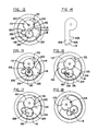
- FIG. 5 shows a schematic diagram of the principal working elements of my invention.
- the lock consists of an outer case 2 which may be a cylinder containing the working parts.
- the multiplicity of levers 4 are pivoted at 6.
- Each lever has a notch 8 in the appropriate position for the lock to operate. Facing the working edges 10 of the levers 4 is a fence 12 operated by a push pin 14 the end of which is in a notch 49 in the outer casing 2.
- a small cylinder 18 is provided with a keyway slot 20 and a key 22 can be inserted into this slot 20 when the cylinder 18 is in the correct initial position as shown in Figures 1 and 5. This is determined by the plate 24 which is fixed to the outside case 2. Thus, the key 22 can enter the lock or be removed from it in only one position.
- Geared to the cylinder 18 containing the key slot 20 is another cylinder 32 ( Figure 3) which has a sector 34 cut out as shown in the Figures 5 to 12. It is designed so that the working portions of the key 22 can enter this cut-out section 34 as the cylinders 18 and 32 rotate with each other. In the final position shown in Figure 8, the two cylinders 18 and 32 have rotated so as to trap the key 22 and/or its slot 20 so as to isolate them from the rest of the mechanisms in the main cylinder 36 ( Figure 8).
- cam section 38 ( Figure 5) which serves two functions. In the position of Figure 8 it contacts cylinder 18, thus acting to provide a better seal between space containing the key 22 and the working elements of the lock. Its second function is to reset the levers 4 as will be explained below.
- levers 4 can be as large as desired, depending on the size of the lock and the precision of construction that can be economically achieved. For example, eight or ten levers present no special problem and each lever can have five to ten possible positions. It is obvious that with normal tolerances of key construction and other mechanical uncertainties, the number of possible positions of each element has to be kept to some reasonable value. Five or six notch positions are very easy to accomplish in an ordinary lock. If the lock is made larger, the number of possible positions can be greatly increased.
- some of the sectors 4 can have more than one notch 8 and this is well understood in the prior art. It should also be noted that if the fence 12 is narrow, the number of possible positions can be larger. This is also true if the fence 12 has very sharp corners and the notches 8 have equally sharp corners. Then, even a small amount of misalignment between the notches and the fence prevents the fence from entering. This action is also well understood in the art.
- FIG. 15 A method of making a key turn disks directly is shown in Figures 15 and 16.
- the key 106 has raised portions, or bits, 108 of various heights and the key 106 can enter suitable notches 102 in the disks 110, and as the key 106 ( Figure 15) tuns, each disk 110 is moved through an appropriate angle.
- a high bit 108 moves the disk through a large angle, and a lower bit 108 moves a disk 110 through a smaller angle, and where there is no raised key section 112 the disk 110 stands still.
- the key shown in Figure 14 is therefore of three bit heights, 0,1 and 2,as shown.
- Each disk 110 is provided with a notch 100 into which a fence 114 can enter.
- the operation of the lock is similar to that of Figures 5 to 12.
- I show a different arrangement of pin interlocks to assure that the key 106 is trapped and isolated from disks 110 before the lock cylinder 116 can be turned.
- the pin 118 is bifurcated into two arms 120 and 122.
- Arm 120 is designed to enter hole 124 as the key 106 starts to turn the cylinder 116 counterclockwise to open the lock.
- Arm 122 is terminated in fence 114.
- the lengths of the two arms 120 and 122 are so proportioned that arm 120 is closer to the cylinder 126 than fence 114, at the end of arm 122, is to the disks 110. This is done so that the arm 120 must enter hole 124 before the fence 114 can determine whether the disks 110 were set correctly.
- the key 106 must turn the cylinder 126 to the position shown in Figure 16 before the fence 114 can cause the lock to open. In this position ( Figure 16) the key is isolated from the lock opening mechanism as was done in the prior-described embodiment.
- two cylinders 126 and 128 are geared together. Cylinder 128 has a sector 130 cut out so as to form part of the isolation chamber for the key 106.
- separator plates 132 are located between the disks 110 so that turning one disk does not move another.
- the fence 114 enters the notches 100 and the inner cylinder 116 can rotate, being no longer prevented from doing so by the pointed pin 118.
- Figure 17 shows the positions of the lock components if a pick is used to turn the cylinders 126 and 128 into the positions shown.
- the arm 120 can enter the hole 124 in cylinder 126, but the fence 114 cannot enter the notches in the incorrectly set disks. In this configuration there is no physical path available to the pick to reach the discs from outside the lock.
- Figure 18 shows the lock after it has been unlocked by a proper key.
- the lock in the case of a lock where elements are set by a key which then, in effect, is removed from further cooperation with the lock, the lock can be considered to be a combination lock.
- the action of a fence entering levers or disks in my lock is not different from that which occurs in a conventional combination lock. It is no easier to test the position of the levers or discs of my lock than it would be to test the position of disks in a conventional combination lock.
- a key can set a much larger number of elements than a dial, such a key lock offers greater protection against surreptitious tampering than the conventional combination lock. A naive question arises as to why not use many more disks in a conventional lock.
- FIG. 19 to 24 Another embodiment is shown in Figures 19 to 24.
- Its settable elements 200 which can be conventional levers, are set by a key 202 as before, but instead of the key 202 being isolated from the levers 200 by a trapping mechanism, the isolation is accomplished by removing the key 202 from the lock entirely and then closing the key slot 204 completely before any attempt can be made to test whether the levers 200 (or other elements) have been set correctly.
- FIG. 19 to 24 a lock having an outside rigid case 206, an inner rotatable cylinder 208 whose top 210 is fitted closely to the upper plate 212 of the case 206. I show a space between them in Figure 21 for clarity only.
- the inner cylinder 208 has a shaft 214 protruding through the top 212 of the lock.
- a knob 216 mounted on the shaft 214 provides the means by which the inner cylinder 208 can be rotated.
- Figure 22 is taken roughly along plane 22-22 of Figure 21.
- the key slot 204 in the top 212 of case 206 is aligned with a similar key slot 218 in the inner cylinder's top plate 210.
- the key 202 such as shown in Figure 20, can be inserted into the lock. It is then turned counterclockwise (viewed from above) approximately 45° to set the levers 200.
- the key 202 after setting the levers 200 is shown by dotted lines in Figure 19.
- the inner cylinder 208 cannot be turned by the knob 216 because the key itself prevents this.
- the key 202 turned clockwise because of the shape of the spring pin 220, (See Figure 22).
- the knob 216 can be turned counterclockwise. This automatically closes the key slot 218 because the two slots 204 and 218 are no longer aligned.
- the new position of the slot 218 in the inner cylinder is as shown in Figure 24. If the levers 200 had been set correctly, a fence 222 operated by the pin 220 acted upon by cam surface 224, enters the notches 226 in the levers 200, as in Figure 23.
- the inner cylinder 208 can now continue turning counterclockwise. It can then operate the rest of a conventional lock mechanism that need not be shown here.
- the knob 16 When it is desired to close the lock, the knob 16 is turned clockwise but before the key slots 204 and 218 become aligned, pin 220 passes down the cam surface 224, fence 22 is withdrawn from the lever notches 226 and the levers 200 can now be reset.
- a vertical rod 228 seen in Figures 21, 22 and 23. It is mounted on plate 230 pivoted at pin 232 mounted on and concentric with the inner cylinder 208.
- a ball detent 234 operated by a spring 236 mounted in the outer, stationary body cylinder of the lock 206 presses against the plate 230 so that as the inner cylinder 208 is rotated clockwise the plate 230 is held back by friction because of the detent 234.
- the rod 228 acts to reset all the levers 200 back to their initial position before the two key slots 204 and 218 are aligned.
- the lock is now ready for another operation.
- the plate can have a serrated edge and the ball detent can be replaced by a pointed pin to increase the forces between them.
- the embodiment shown is by way of an example only and ratchets of various types are well known to the art so that the plate 230 can be held back as the inner cylinder is rotated clockwise (looking from above).
- FIGs 25 and 26 show still another embodiment of my invention.
- the design is similar to the first embodiment, as shown in Figures 1 to 12, and the drawings are simplified schematics taken just below the front plate of the lock as was done in Figure 5.
- the lock has an outside body cylinder 300 and an inner cylinder 302. To open the lock the inner cylinder 302 must be rotated. This is identical in operation with a great many locks used throughout the world.
- a set of levers 304 that must be correctly set by a key 306 so that a fence 308 should be able to enter notches 310 in these sectors 304.
- a key cylinder 312 is located in the inner cylinder 302, and is provided with a key slot 314.
- the key 306 that can be identical to key 22 as shown in Figure 4, can be inserted through a suitable opening 20 in the top late 24 of the lock as shown in Figures 1 and 3.
- this last embodiment does not contain a second cylinder (32 of Figures 3 and 5) to isolate the key 306 after it has set the sectors 304. Instead, I use a swinging plate 316 pivoted on shaft 318. The plate 316 is driven by a small diameter pinion gear 320 affixed to shaft 318. This gear 320 is acted upon by a short rack 322 that is a part of pin 324.
- the resetting of the levers 304 is accomplished in a manner somewhat similar to that of the first embodiment ( Figures 3 to 12), except that the key cylinder 312 itself has a cam 326 at its lower end for this purpose.
- the cam 326 acts on a sliding pin 328 mounted for lengthwise movement in the base of the cylinder 302.
- a vertical rod 330 is fastened to the pin 328 at its left end as seen in Figures 25 and 26, and this vertical rod 330 resets the levers 304 when the key cylinder is rotated clockwise to its initial position as seen in Figure 25.
- the key cylinder 312 is provided with a small hole 332 into which pin 334 must enter before the lock can be opened.
- a proper key 306 is inserted into the key slot 314 in the key cylinder 312.
- the key 306 is turned counterclockwise about 300 degrees till it is stopped by the solid parts of the inner cylinder 302 as shown in Figure 26.
- the inner cylinder 302 is now free to continue rotation.
- the fence pin 336 reaches the cam surface 346 of the wide notch 348 in the outer case 300, and because the sectors 304 had been correctly set, as stated, the fence 308 enters the notches 310 and the lock can be opened.
Landscapes
- Lock And Its Accessories (AREA)
Applications Claiming Priority (2)
| Application Number | Priority Date | Filing Date | Title |
|---|---|---|---|
| US06/796,070 US4599877A (en) | 1985-11-08 | 1985-11-08 | Key lock with key isolation |
| US796070 | 1985-11-08 |
Publications (2)
| Publication Number | Publication Date |
|---|---|
| EP0227236A2 true EP0227236A2 (de) | 1987-07-01 |
| EP0227236A3 EP0227236A3 (de) | 1988-06-08 |
Family
ID=25167196
Family Applications (1)
| Application Number | Title | Priority Date | Filing Date |
|---|---|---|---|
| EP19860307992 Withdrawn EP0227236A3 (de) | 1985-11-08 | 1986-10-15 | Schloss, in dem der Schlüssel von den Zuhaltungen getrennt und isoliert wird |
Country Status (3)
| Country | Link |
|---|---|
| US (1) | US4599877A (de) |
| EP (1) | EP0227236A3 (de) |
| CA (1) | CA1283792C (de) |
Families Citing this family (6)
| Publication number | Priority date | Publication date | Assignee | Title |
|---|---|---|---|---|
| US4739639A (en) * | 1986-09-25 | 1988-04-26 | Cathirgamathamby Balasingam | Auto-directing lever lock |
| US4796448A (en) * | 1986-10-22 | 1989-01-10 | Jacob Rabinow | Lock with reference plate |
| US4796447A (en) * | 1987-07-09 | 1989-01-10 | Jacob Rabinow | Lock with key isolation using transfer tumblers |
| US5671623A (en) * | 1995-12-04 | 1997-09-30 | Hsu; Yun-Tung | Lock assembly with a curved keyway and a flexible key for actuation thereof |
| DE102010038105B4 (de) * | 2010-10-11 | 2012-05-24 | André Haake | Verfahren zur Kodierung eines Schlosses und Rohteil zur Durchführung dieses Verfahrens |
| US20180010365A1 (en) * | 2016-06-23 | 2018-01-11 | Felix Zolotinsky | Mechanical lock and method of operation thereof |
Family Cites Families (16)
| Publication number | Priority date | Publication date | Assignee | Title |
|---|---|---|---|---|
| US473857A (en) * | 1892-04-26 | Eugene c | ||
| US615206A (en) * | 1898-11-29 | Webster davis | ||
| US412867A (en) * | 1889-10-15 | Key-hole guard | ||
| US180255A (en) * | 1876-07-25 | Improvement in latch-locks | ||
| US412997A (en) * | 1889-10-15 | taylor | ||
| US1702430A (en) * | 1922-12-05 | 1929-02-19 | Jules A Fremon | Lock |
| US1904882A (en) * | 1929-04-20 | 1933-04-18 | August F W Viehweger | Burglarproof lock |
| US2179947A (en) * | 1936-04-01 | 1939-11-14 | Miller Samuel | Lock |
| US2528964A (en) * | 1945-12-07 | 1950-11-07 | Lurtz Carl | Antipick keylock mechanism |
| US2696727A (en) * | 1951-05-02 | 1954-12-14 | Schlabach Raymond | Antipick lock |
| US3172283A (en) * | 1962-02-23 | 1965-03-09 | Rabinow Jacob | Combination lock with security mechanism |
| AT270430B (de) * | 1966-01-04 | 1969-04-25 | Viro Innocenti Spa | Schließzylinder für rechte und linke Zylinderschlösser |
| US3367155A (en) * | 1966-05-16 | 1968-02-06 | Gen Motors Corp | Lock cylinder assembly |
| US3367156A (en) * | 1966-05-25 | 1968-02-06 | Gen Motors Corp | Lock cylinder assembly |
| US4111019A (en) * | 1977-02-22 | 1978-09-05 | Hall & Myers | Pickproof lock |
| US4485648A (en) * | 1982-09-27 | 1984-12-04 | Jacob Rabinow | Key lock with a flying sidebar |
-
1985
- 1985-11-08 US US06/796,070 patent/US4599877A/en not_active Expired - Fee Related
-
1986
- 1986-09-11 CA CA 518037 patent/CA1283792C/en not_active Expired - Lifetime
- 1986-10-15 EP EP19860307992 patent/EP0227236A3/de not_active Withdrawn
Also Published As
| Publication number | Publication date |
|---|---|
| CA1283792C (en) | 1991-05-07 |
| EP0227236A3 (de) | 1988-06-08 |
| US4599877A (en) | 1986-07-15 |
Similar Documents
| Publication | Publication Date | Title |
|---|---|---|
| US3605463A (en) | Pickproof cylinder lock | |
| US4325240A (en) | Locking mechanism | |
| US4282731A (en) | Pin-tumbler-type lock having antipick security action | |
| US3499302A (en) | Cylinder lock | |
| EP1013858A1 (de) | Kombinationsvorhängeschloss | |
| US4249469A (en) | Safe having combination locking mechanisms | |
| CA2097002C (en) | Pin tumbler locks and keys therefor | |
| US5177466A (en) | Lock structure with a warning device | |
| US3447348A (en) | Combination locker locks | |
| US4599877A (en) | Key lock with key isolation | |
| US3486353A (en) | Lock mechanisms and keys therefor | |
| US4031730A (en) | Tamperproof lock and method | |
| US20040182120A1 (en) | Locker Lock | |
| US3906761A (en) | Disabling mechanism for a combination lock | |
| GB2041440A (en) | Magnetic lock | |
| US4151731A (en) | Pick resistant cylinder lock | |
| US3928993A (en) | Pickproof cylinder lock | |
| US3772904A (en) | Lock with changeable guard and locking keys | |
| US3786658A (en) | Restrictive manipulation limited try mechanism for a combination lock | |
| CA1227941A (en) | Locks | |
| US3533253A (en) | Changeable combination padlock | |
| US5052205A (en) | Lock cylinder having a slide plate with one or more rows of pin tumblers and key therefor | |
| US4320637A (en) | Key removable cylinder assembly from locket | |
| US3402581A (en) | Key operated lock | |
| US20240218697A1 (en) | Door locking device |
Legal Events
| Date | Code | Title | Description |
|---|---|---|---|
| PUAI | Public reference made under article 153(3) epc to a published international application that has entered the european phase |
Free format text: ORIGINAL CODE: 0009012 |
|
| AK | Designated contracting states |
Kind code of ref document: A2 Designated state(s): CH DE GB LI |
|
| PUAL | Search report despatched |
Free format text: ORIGINAL CODE: 0009013 |
|
| AK | Designated contracting states |
Kind code of ref document: A3 Designated state(s): CH DE GB LI |
|
| 17P | Request for examination filed |
Effective date: 19880915 |
|
| 17Q | First examination report despatched |
Effective date: 19890627 |
|
| STAA | Information on the status of an ep patent application or granted ep patent |
Free format text: STATUS: THE APPLICATION HAS BEEN WITHDRAWN |
|
| 18W | Application withdrawn |
Withdrawal date: 19900706 |
|
| R18W | Application withdrawn (corrected) |
Effective date: 19900706 |