EP0226969B1 - Device for making a reaction mixture from at least two components of a synthetic material - Google Patents
Device for making a reaction mixture from at least two components of a synthetic material Download PDFInfo
- Publication number
- EP0226969B1 EP0226969B1 EP86117282A EP86117282A EP0226969B1 EP 0226969 B1 EP0226969 B1 EP 0226969B1 EP 86117282 A EP86117282 A EP 86117282A EP 86117282 A EP86117282 A EP 86117282A EP 0226969 B1 EP0226969 B1 EP 0226969B1
- Authority
- EP
- European Patent Office
- Prior art keywords
- gas
- feed
- component
- line
- components
- Prior art date
- Legal status (The legal status is an assumption and is not a legal conclusion. Google has not performed a legal analysis and makes no representation as to the accuracy of the status listed.)
- Expired - Lifetime
Links
Images

Classifications
-
- B—PERFORMING OPERATIONS; TRANSPORTING
- B29—WORKING OF PLASTICS; WORKING OF SUBSTANCES IN A PLASTIC STATE IN GENERAL
- B29B—PREPARATION OR PRETREATMENT OF THE MATERIAL TO BE SHAPED; MAKING GRANULES OR PREFORMS; RECOVERY OF PLASTICS OR OTHER CONSTITUENTS OF WASTE MATERIAL CONTAINING PLASTICS
- B29B7/00—Mixing; Kneading
- B29B7/74—Mixing; Kneading using other mixers or combinations of mixers, e.g. of dissimilar mixers ; Plant
- B29B7/76—Mixers with stream-impingement mixing head
- B29B7/7615—Mixers with stream-impingement mixing head characterised by arrangements for controlling, measuring or regulating, e.g. for feeding or proportioning the components
- B29B7/7621—Mixers with stream-impingement mixing head characterised by arrangements for controlling, measuring or regulating, e.g. for feeding or proportioning the components involving introducing a gas or another component in at least one of the components
-
- B—PERFORMING OPERATIONS; TRANSPORTING
- B01—PHYSICAL OR CHEMICAL PROCESSES OR APPARATUS IN GENERAL
- B01F—MIXING, e.g. DISSOLVING, EMULSIFYING OR DISPERSING
- B01F23/00—Mixing according to the phases to be mixed, e.g. dispersing or emulsifying
- B01F23/20—Mixing gases with liquids
- B01F23/23—Mixing gases with liquids by introducing gases into liquid media, e.g. for producing aerated liquids
Definitions
- the invention relates to a device according to the preamble of patent claim 1.
- Such a device is known from DE-OS 34 16 442.
- a measuring device is provided in the ring line or in the bypass, which determines the gas content in the corresponding plastic component and thus regulates the gas loading itself.
- the measuring device reacts not only to the gas load but also to other additives in the plastic component, e.g. Water, fiberglass and other additives.
- the measurement is falsified by these additives.
- the invention is therefore based on the object of creating a device according to the preamble of claim 1, in which the measurement of the gas load is carried out more precisely and in particular is as independent as possible of further additives in the corresponding plastic component.
- the second measuring device which is connected in parallel with the first, but which operates under higher pressure.
- the first measuring device normally works at tank pressure, whereas the pressure under which the second measuring device connected in parallel is so high that the gases taken up are practically completely compressed, i.e. have gone into solution so that they are no longer registered by this second measuring device. Only the aggregates are recorded. If the measured values of the two measuring devices or the corresponding measurement signals are compared with one another in a device, for example a computer or a comparator circuit, it is then easily possible to calculate the actual gas load exactly, so that errors caused by more or less high levels Proportions of aggregates can be avoided.
- capacitive measuring probes which are known per se and are commercially available, have proven to be particularly useful as measuring devices.
- such measuring probes as are suitable for the continuous level measurement are used.
- These consist essentially of an electrode head, in which the electronics insert is also installed, and the actual electrodes as a measuring part, which can be designed, for example, in the form of a tube with a central rod.
- the capacitive measurement is based on the determination of the dielectric constant of the plastic components, which changes due to additives such as glass fibers, water or dispersed gas bubbles.
- Other measuring devices that work according to other physical principles, for example density measuring devices, can also be used.
- the value calculated in the device for the gas loading of the component can be fed to a control device which, depending on an adjustable setpoint, actuates an actuator for a valve regulating the gas supply.
- a control device which, depending on an adjustable setpoint, actuates an actuator for a valve regulating the gas supply.
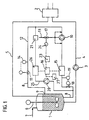
- a high-pressure mixing device with a storage container (1) for a component and a mixing head (2) is shown schematically in FIGS. 1 and 2.
- the storage container and mixing head are connected to one another via a feed line (4) containing a metering pump (3) and a return line (5).
- a stirrer (6) is indicated in the storage container.
- With (7) a gas supply line is designated, via which a certain container pressure is maintained.
- the storage container and the line system for the other component are not shown to simplify the drawing.
- a ring line (8) which is guided in a separate circuit is connected to the storage container (1) and opens into the storage container again at (9) (FIG. 1).
- a feed pump (10) and a throttle element (11) are provided in the ring line.
- the section (12) of the ring line between the feed pump and throttle element is designed as a compression zone.
- the component to be loaded with gas is circulated by the feed pump (10) before it is mixed with the other component.
- the gas is supplied via the gas feed line (13) into the suction area and / or pressure area of the feed pump, if necessary also directly into the feed pump.
- the measured value can be displayed directly and used to adjust the throttling device by hand. It is also possible to use the measured value for the automatic regulation of the throttle element via an adjusting device.
- the component circuit which is independent of the metering pump (3), makes it possible to continuously condition the component in the storage container (1) to a predetermined gas content, regardless of the operating state of the other mixing device.
- there are additional advantages for example by interruptions to the gas loading of one or both components, which are otherwise inevitable, can be avoided.
- a corresponding measuring device (15) is attached in the ring line (8) in front of the feed pump (10) to determine the gas content of the component.
- the measuring device is coupled to a device (16) which acts on a control device (23).
- a throttle valve (18) is provided in front of the measuring device (15), by means of which the component pressure can be reduced to a value below the tank pressure. This value is determined via the setpoint device (19). In this way, in addition to the gas fraction present in the component, the gas fraction dissolved in the component can also be partially or completely determined.
- the degree of gas loading of one or both components is determined in a bypass (25) which is drawn off from the ring line (8) and fed back to it.
- the bypass (25) contains a second measuring device (26) operating under high pressure, which is connected in parallel to the first measuring device (15).
- a pump (2O) and a preload valve (21) are provided in the bypass to increase the pressure of the plastic component.
- the values determined by the measuring device (26) are also fed to the device (16), compared with the measured values of the first measuring device (15) and the value of the gas load is calculated therefrom and displayed at (27).
- the control device (23) is connected to the device (16), in which the value of the gas load is compared with a predetermined target value. In the event of deviations from this comparison, the actuator (24) for a valve (17) is actuated by the control device.
- the gas loading of one or both plastic components takes place in a bypass (22) between the feed line (4) and the return line (5).
- a first measuring device (15) which is connected to the device (16), is provided for determining the gas content.
- the output of the device (16) is connected to the control device (23).
- the bypass further contains a throttle valve (18), a setpoint device (19), a feed pump (10) with a gas supply line (13), a valve (17) and an actuator (24), as well as a throttle device (11) and a measured value transmitter (14 ).
- the second measuring device (26) operating under high pressure is mounted downstream of the metering pump (3) in the feed line (4). The pressure increase in the plastic component required for a more precise determination of the gas loading by the second measuring device is achieved with the aid of the metering pump (3) and with nozzles present in the mixing head (2).
- the two measuring devices (15) and (26) deliver corresponding signals which are compared in a control device (23) connected to the device (16) in order to calculate the actual gas loading regardless of the proportion of further additives in the plastic component.
- the further construction of this device corresponds to the embodiment shown in FIG. 1 and described above.
- the actual gas content of a plastic component can be determined with high accuracy or can be determined extremely precisely by means of a corresponding regulation.
Description
Die Erfindung betrifft eine Vorrichtung nach dem Oberbegriff des Patentanspruchs 1.The invention relates to a device according to the preamble of patent claim 1.
Eine derartige Vorrichtung ist aus der DE-OS 34 16 442 bekannt. Bei dem in dieser Offenlegungsschrift beschriebenen Verfahren und der entsprechenden Vorrichtung ist in der Ringleitung bzw. in dem Bypass ein Meßgerät vorgesehen, das den Gasgehalt in der entsprechenden Kunststoffkomponente feststellt und so die Gasbeladung selbst regelt.Such a device is known from DE-OS 34 16 442. In the method and the corresponding device described in this published specification, a measuring device is provided in the ring line or in the bypass, which determines the gas content in the corresponding plastic component and thus regulates the gas loading itself.
Es hat sich nun herausgestellt, daß bei einigen Anwendungsfällen diese Art der Messung noch nicht zufriedenstellend ist. Das Meßgerät reagiert nämlich nicht nur auf die Gasbeladung sondern auch auf andere Zuschlagstoffe in der Kunststoffkomponente, wie z.B. Wasser, Glasfasern und andere Zusätze. Durch diese Zuschlagstoffe wird die Messung verfälscht.It has now been found that this type of measurement is not yet satisfactory in some applications. The measuring device reacts not only to the gas load but also to other additives in the plastic component, e.g. Water, fiberglass and other additives. The measurement is falsified by these additives.
Der Erfindung liegt daher die Aufgabe zugrunde, eine Vorrichtung nach dem Oberbegriff des Anspruches 1 zu schaffen, bei der die Messung der Gasbeladung exakter erfolgt und insbesondere möglichst unabhängig von weiteren Zuschlagstoffen in der entsprechenden Kunststoffkomponente ist.The invention is therefore based on the object of creating a device according to the preamble of claim 1, in which the measurement of the gas load is carried out more precisely and in particular is as independent as possible of further additives in the corresponding plastic component.
Diese Aufgabe wird durch das Kennzeichen des Anspruches 1 gelöst.This object is achieved by the characterizing part of claim 1.
Erfindungsgemäß ist also ein zweites Meßgerät vorhanden, das dem ersten parallel geschaltet ist, das aber unter höherem Druck arbeitet. Das erste Meßgerät arbeitet normalerweise bei Tankdruck, wohingegen der Druck, unter dem das zweite parallel geschaltete Meßgerät arbeitet, so hoch liegt, daß die aufgenommenen Gase praktisch vollständig komprimiert, d.h. in Lösung gegangen sind, so daß sie von diesem zweiten Meßgerät nicht mehr registriert werden. Erfaßt werden lediglich die Zuschlagstoffe. Werden die Meßwerte der beiden Meßgeräte bzw. die entsprechenden Meßsignale in einer Einrichtung, beispielsweise einem Rechner oder einer Komperatorschaltung, miteinander verglichen, so ist es dann ohne weiteres möglich, die wirkliche Gasbeladung exakt zu berechnen, so daß Fehler, bedingt durch mehr oder weniger hohe Anteile an Zuschlagstoffen, vermieden werden.According to the invention, there is therefore a second measuring device which is connected in parallel with the first, but which operates under higher pressure. The first measuring device normally works at tank pressure, whereas the pressure under which the second measuring device connected in parallel is so high that the gases taken up are practically completely compressed, i.e. have gone into solution so that they are no longer registered by this second measuring device. Only the aggregates are recorded. If the measured values of the two measuring devices or the corresponding measurement signals are compared with one another in a device, for example a computer or a comparator circuit, it is then easily possible to calculate the actual gas load exactly, so that errors caused by more or less high levels Proportions of aggregates can be avoided.
Als besonders zweckmäßig haben sich als Meßgeräte sog. kapazitive Meßsonden herausgestellt, welche an sich bekannt und handelsüblich sind. Geeignet sind beispielsweise solche Meßsonden, wie sie für die kotinuierliche Füllstandsmessung Verwendung finden. Diese bestehen im wesentlichen aus einem Elektrodenkopf, in dem auch der Elektronikeinsatz eingebaut ist und den eigentlichen Elektroden als Meßteil, die z.B. in Form eines Rohres mit zentralem Stab ausgebildet sein können. Die kapazitive Messung beruht dabei auf der Bestimmung der Dielektrizitätskonstanten der Kunststoffkomponenten, die sich durch Zuschlagstoffe, wie Glasfasern, Wasser oder dispergierte Gasblasen verändert. Andere Meßgeräte, die nach anderen physikalischen Prinzipien arbeiten, z.B. Dichtemeßgeräte, sind ebenfalls einsetzbar.So-called capacitive measuring probes, which are known per se and are commercially available, have proven to be particularly useful as measuring devices. For example, such measuring probes as are suitable for the continuous level measurement are used. These consist essentially of an electrode head, in which the electronics insert is also installed, and the actual electrodes as a measuring part, which can be designed, for example, in the form of a tube with a central rod. The capacitive measurement is based on the determination of the dielectric constant of the plastic components, which changes due to additives such as glass fibers, water or dispersed gas bubbles. Other measuring devices that work according to other physical principles, for example density measuring devices, can also be used.
Nach einem weiteren Merkmal der Erfindung ist der in der Einrichtung errechnete Wert für die Gasbeladung der Komponente einem Regelgerät zuführbar, welches in Abhängigkeit von einem einstellbaren Sollwert ein Stellglied für ein die Gaszufuhr regelndes Ventil betätigt. Auf diese Weise läßt sich der Gasgehalt einer Komponente mit hoher Genauigkeit und ohne manuellen Eingriff einstellen.According to a further feature of the invention, the value calculated in the device for the gas loading of the component can be fed to a control device which, depending on an adjustable setpoint, actuates an actuator for a valve regulating the gas supply. In this way, the gas content of a component can be adjusted with high accuracy and without manual intervention.
Im folgenden wird die erfindungsgemäße Vorrichtung unter Hinweis auf die Zeichnungen näher erläutert.The device according to the invention is explained in more detail below with reference to the drawings.
In den Figuren 1 und 2 ist schematisch eine Hochdruckmischvorrichtung mit einem Vorratsbehälter (1) für eine Komponente und einem Mischkopf (2) dargestellt. Vorratsbehälter und Mischkopf sind über eine eine Dosierpumpe (3) enthaltende Zuführleitung (4) sowie eine Rückführleitung (5) miteinander verbunden. Im Vorratsbehälter ist ein Rührer (6) angedeutet. Mit (7) ist eine Gaszuleitung bezeichnet, über welche ein bestimmter Behälterdruck aufrechterhalten wird. Der Vorratsbehälter sowie das Leitungssystem für die andere Komponente sind zur Vereinfachung der zeichnerischen Darstellung nicht gezeigt.A high-pressure mixing device with a storage container (1) for a component and a mixing head (2) is shown schematically in FIGS. 1 and 2. The storage container and mixing head are connected to one another via a feed line (4) containing a metering pump (3) and a return line (5). A stirrer (6) is indicated in the storage container. With (7) a gas supply line is designated, via which a certain container pressure is maintained. The storage container and the line system for the other component are not shown to simplify the drawing.
An den Vorratsbehälter (1) ist eine in einem getrennten Kreislauf geführte Ringleitung (8) angeschlossen, die bei (9) wieder in den Vorratsbehälter mündet (Figur 1). In der Ringleitung sind eine Förderpumpe (1O) und ein Drosselorgan (11) vorgesehen. Der Abschnitt (12) der Ringleitung zwischen Förderpumpe und Drosselorgan ist als Kompressionszone ausgebildet.A ring line (8) which is guided in a separate circuit is connected to the storage container (1) and opens into the storage container again at (9) (FIG. 1). A feed pump (10) and a throttle element (11) are provided in the ring line. The section (12) of the ring line between the feed pump and throttle element is designed as a compression zone.
Die mit Gas zu beladene Komponente wird vor ihrer Vermischung mit der anderen Komponente durch die Förderpumpe (1O) im Kreislauf umgewälzt. Dabei erfolgt die Zufuhr des Gases über die Gaszuleitung (13) in den Saugbereich und/oder Druckbereich der Förderpumpe, gegebenenfalls auch direkt in die Förderpumpe. Durch die Förderpumpe sowie das Drosselorgan (11) wird der in der Kompressionszone (12) für eine wirkungsvolle Absorption des Gases erforderliche Druck eingestellt und mittels eines Meßwertgebers (14) gemessen. Der Meßwert kann direkt angezeigt und zur Einstellung des Drosselorgans von Hand verwendet werden. Es ist ebenso möglich, den Meßwert zur automatischen Regelung des Drosselorgans über eine Verstelleinrichtung zu verwenden.The component to be loaded with gas is circulated by the feed pump (10) before it is mixed with the other component. The gas is supplied via the gas feed line (13) into the suction area and / or pressure area of the feed pump, if necessary also directly into the feed pump. Through the feed pump and the throttle element (11) in the compression zone (12) for an effective Absorption of the gas required pressure set and measured by means of a sensor (14). The measured value can be displayed directly and used to adjust the throttling device by hand. It is also possible to use the measured value for the automatic regulation of the throttle element via an adjusting device.
Durch den von der Dosierpumpe (3) unabhängigen Komponentenkreislauf wird eine kontinuierliche Konditionierung der Komponente im Vorratsbehälter (1) auf einen vorgegebenen Gasgehalt, unabhängig vom Betriebszustand der übrigen Mischvorrichtung, möglich. Insbesondere bei Produktionsanlagen mit hohen Ausstoßleistungen und kurzen Pausenzeiten, in denen keine Vermischung mit der anderen Komponente stattfindet, ergeben sich zusätzliche Vorteile, indem z.B. sonst zwangsläufig erforderliche Unterbrechungen zur Gasbeladung einer oder beider Komponenten vermieden werden.The component circuit, which is independent of the metering pump (3), makes it possible to continuously condition the component in the storage container (1) to a predetermined gas content, regardless of the operating state of the other mixing device. In particular in the case of production plants with high output rates and short break times in which there is no mixing with the other component, there are additional advantages, for example by interruptions to the gas loading of one or both components, which are otherwise inevitable, can be avoided.
Zur Bestimmung des Gasgehalts der Komponente ist in der Ringleitung (8) vor der Förderpumpe (1O) ein entsprechendes Meßgerät (15) angebracht. Das Meßgerät ist mit einer Einrichtung (16) gekoppelt, die auf ein Regelgerät (23) wirkt.A corresponding measuring device (15) is attached in the ring line (8) in front of the feed pump (10) to determine the gas content of the component. The measuring device is coupled to a device (16) which acts on a control device (23).
Für eine Steigerung der Meßgenauigkeit der Gasbeladung ist vor dem Meßgerät (15) ein Drosselventil (18) vorgesehen, über welches der Komponentendruck auf einen Wert unterhalb des Behälterdruckes abgesenkt werden kann. Dieser Wert wird über den Sollwertgeber (19) bestimmt. Auf diese Weise sind neben dem in der Komponente dispergiert vorliegenden Gasanteil auch der in der Komponente gelöste Gasanteil teilweise oder vollständig erfaßbar.To increase the measuring accuracy of the gas load, a throttle valve (18) is provided in front of the measuring device (15), by means of which the component pressure can be reduced to a value below the tank pressure. This value is determined via the setpoint device (19). In this way, in addition to the gas fraction present in the component, the gas fraction dissolved in the component can also be partially or completely determined.
Weiterhin wird der Grad der Gasbeladung einer oder beider Komponenten in einem von der Ringleitung (8) ab- und auf sie wieder zugeführten Bypass (25) bestimmt. Hierfür enthält der Bypass (25) ein zweites unter hohem Druck arbeitendes Meßgerät (26), welches zu dem ersten Meßgerät (15) parallel geschaltet ist. Für die erforderliche Druckerhöhung der Kunststoffkomponente sind in dem Bypass eine Pumpe (2O) sowie ein Vorspannventil (21) vorgesehen. Die durch das Meßgerät (26) festgestellten Werte werden ebenfalls auf die Einrichtung (16) geführt, mit den Meßwerten des ersten Meßgerätes (15) verglichen und daraus der Wert der Gasbeladung errechnet und bei (27) angezeigt. An die Einrichtung (16) ist das Regelgerät (23) angeschlossen, in dem der Wert der Gasbeladung mit einem vorgegebenen Sollwert verglichen wird. Bei Abweichungen aus diesem Vergleich wird das Stellglied (24) für ein Ventil (17) durch das Regelgerät betätigt.Furthermore, the degree of gas loading of one or both components is determined in a bypass (25) which is drawn off from the ring line (8) and fed back to it. For this purpose, the bypass (25) contains a second measuring device (26) operating under high pressure, which is connected in parallel to the first measuring device (15). A pump (2O) and a preload valve (21) are provided in the bypass to increase the pressure of the plastic component. The values determined by the measuring device (26) are also fed to the device (16), compared with the measured values of the first measuring device (15) and the value of the gas load is calculated therefrom and displayed at (27). The control device (23) is connected to the device (16), in which the value of the gas load is compared with a predetermined target value. In the event of deviations from this comparison, the actuator (24) for a valve (17) is actuated by the control device.
Gemäß Figur 2 erfolgt die Gasbeladung einer oder beider Kunststoffkomponenten in einem Bypass (22) zwischen der Zuführleitung (4) und der Rückführleitung (5). Zur Bestimmung des Gasgehalts ist ein erstes Meßgerät (15) vorgesehen, welches mit der Einrichtung (16) verbunden ist. Der Ausgang der Einrichtung (16) ist auf das Regelgerät (23) geschaltet. Der Bypass enthält weiter ein Drosselventil (18), einen Sollwertgeber (19), eine Förderpumpe (1O) mit einer Gaszuleitung (13), einem Ventil (17) und einem Stellglied (24) sowie ein Drosselorgan (11) und einen Meßwertgeber (14). Das zweite unter hohem Druck arbeitende Meßgerät (26) ist stromab von der Dosierpumpe (3) in der Zuführleitung (4) angebracht. Die für eine genauere Bestimmung der Gasbeladung durch das zweite Meßgerät erforderliche Druckerhöhung der Kunststoffkomponente wird mit Hilfe der Dosierpumpe (3) und mit im Mischkopf (2) vorhandenen Düsen erreicht.According to FIG. 2, the gas loading of one or both plastic components takes place in a bypass (22) between the feed line (4) and the return line (5). A first measuring device (15), which is connected to the device (16), is provided for determining the gas content. The output of the device (16) is connected to the control device (23). The bypass further contains a throttle valve (18), a setpoint device (19), a feed pump (10) with a gas supply line (13), a valve (17) and an actuator (24), as well as a throttle device (11) and a measured value transmitter (14 ). The second measuring device (26) operating under high pressure is mounted downstream of the metering pump (3) in the feed line (4). The pressure increase in the plastic component required for a more precise determination of the gas loading by the second measuring device is achieved with the aid of the metering pump (3) and with nozzles present in the mixing head (2).
Die beiden Meßgeräte (15) und (26) liefern entsprechende Signale, die in einem an die Einrichtung (16) angeschlossenen Regelgerät (23) verglichen werden, um die tatsächliche Gasbeladung unabhängig von dem Anteil an weiteren Zuschlagstoffen in der Kunststoffkomponente zu berechnen. Der weitere Aufbau dieser Vorrichtung entspricht der in Figur 1 gezeigten und vorstehend beschriebenen Ausführungsform.The two measuring devices (15) and (26) deliver corresponding signals which are compared in a control device (23) connected to the device (16) in order to calculate the actual gas loading regardless of the proportion of further additives in the plastic component. The further construction of this device corresponds to the embodiment shown in FIG. 1 and described above.
Nach der Erfindung läßt sich der tatsächliche Gasgehalt einer Kunststoffkomponente mit hoher Genauigkeit ermitteln bzw. durch eine entsprechende Regelung äußerst exakt festlegen.According to the invention, the actual gas content of a plastic component can be determined with high accuracy or can be determined extremely precisely by means of a corresponding regulation.
Claims (3)
- Apparatus for producing a reaction mixture of two or more plastics components, in particular those based on polyurethane, comprising a stock tank (1) for each plastics component and a mixing head (2) which is connected to the stock tanks via feed lines (4) containing metering pumps (3) and return lines (5), as well as one or more gas feed lines (13) into the pipeline system of one or more components, which feed line ends in a ring line (8) provided with a feed pump (10) and connected to the stock tanks, or in a bypass (22) between the feed line and the return line, a first meter (15) for determining the gas content of the component being provided in the ring line or in the bypass upstream of the feed pump (10), wherein a second meter (26) operating under high pressure is connected in parallel with the first meter (15), and a unit (16) which compares the measured values from the two meters (15, 26), calculates the gas content from this and controls the gas supply is provided.
- Apparatus as claimed in claim 1, wherein the meters are capacitive measuring probes.
- Apparatus as claimed in claim 1, wherein the gas content of the component which is calculated in the unit (16) can be fed to a controller (23) which, as a function of a settable set-point value, actuates a final control element (24) for a valve (17) which regulates the gas feed.
Applications Claiming Priority (2)
| Application Number | Priority Date | Filing Date | Title |
|---|---|---|---|
| DE3544914 | 1985-12-19 | ||
| DE19853544914 DE3544914A1 (en) | 1985-12-19 | 1985-12-19 | DEVICE FOR PRODUCING A REACTION MIXTURE FROM AT LEAST TWO PLASTIC COMPONENTS |
Publications (3)
| Publication Number | Publication Date |
|---|---|
| EP0226969A2 EP0226969A2 (en) | 1987-07-01 |
| EP0226969A3 EP0226969A3 (en) | 1989-03-22 |
| EP0226969B1 true EP0226969B1 (en) | 1991-05-15 |
Family
ID=6288836
Family Applications (1)
| Application Number | Title | Priority Date | Filing Date |
|---|---|---|---|
| EP86117282A Expired - Lifetime EP0226969B1 (en) | 1985-12-19 | 1986-12-11 | Device for making a reaction mixture from at least two components of a synthetic material |
Country Status (3)
| Country | Link |
|---|---|
| EP (1) | EP0226969B1 (en) |
| JP (1) | JPS62148515A (en) |
| DE (2) | DE3544914A1 (en) |
Families Citing this family (3)
| Publication number | Priority date | Publication date | Assignee | Title |
|---|---|---|---|---|
| EP0317801B1 (en) * | 1987-11-07 | 1995-01-11 | Phoenix Aktiengesellschaft | Process for preparing soft integral polyurethane foam articles |
| US5082142A (en) * | 1989-08-04 | 1992-01-21 | Nordson Corporation | Method and apparatus for applying non-chemically foamed multi-component curable polymers |
| DE4235970C1 (en) * | 1992-10-26 | 1993-11-25 | Bayer Ag | Device for producing a foam-forming reaction mixture |
Family Cites Families (4)
| Publication number | Priority date | Publication date | Assignee | Title |
|---|---|---|---|---|
| DE2317152B2 (en) * | 1973-04-05 | 1977-06-30 | Maschinenfabrik Hennecke Gmbh, 5090 Leverkusen | METHOD AND DEVICE FOR PRODUCING FOAM, IN PARTICULAR POLYURETHANE FOAM, FROM A FLOWABLE REACTION MIXTURE |
| GB2125308A (en) * | 1982-07-30 | 1984-03-07 | Polyrim Mfg | Apparatus for nucleating a liquid chemical constituent of a reaction injection molding system |
| DE3244037A1 (en) * | 1982-11-27 | 1984-05-30 | Bayer Ag, 5090 Leverkusen | METHOD AND DEVICE FOR PRODUCING A FLOWABLE, MIXTURE OF FLOWABLE COMPONENTS COMPRISING TO FOAM |
| DE3416442A1 (en) * | 1983-05-07 | 1984-11-08 | Basf Ag, 6700 Ludwigshafen | Process and device for producing a reactive mixture of at least two components for the production of foams |
-
1985
- 1985-12-19 DE DE19853544914 patent/DE3544914A1/en not_active Withdrawn
-
1986
- 1986-12-03 JP JP61286869A patent/JPS62148515A/en active Pending
- 1986-12-11 DE DE8686117282T patent/DE3679296D1/en not_active Expired - Lifetime
- 1986-12-11 EP EP86117282A patent/EP0226969B1/en not_active Expired - Lifetime
Also Published As
| Publication number | Publication date |
|---|---|
| DE3679296D1 (en) | 1991-06-20 |
| EP0226969A3 (en) | 1989-03-22 |
| DE3544914A1 (en) | 1987-06-25 |
| EP0226969A2 (en) | 1987-07-01 |
| JPS62148515A (en) | 1987-07-02 |
Similar Documents
| Publication | Publication Date | Title |
|---|---|---|
| EP0239720B1 (en) | Process and apparatus for preparing a fluid foaming reaction mixture from fluid components | |
| EP0344501A1 (en) | Method and device for continuously charging a liquid reactive component with a gas for making a foamy reactive mixture | |
| DE2543302A1 (en) | METHOD AND DEVICE FOR PREPARING REACTION MIXTURES FROM LIQUID REACTION COMPONENTS, IN PARTICULAR FOR THE PRODUCTION OF POLYURETHANE FOAMS | |
| DE2724132C3 (en) | Method and apparatus for producing a foam-forming reaction mixture | |
| EP0940189A2 (en) | Powder coating installation and method for supplying and mixing powder in this installation | |
| EP0597374B1 (en) | Method and device for mixing gases | |
| EP0238796A2 (en) | Apparatus and method for the manufacturing of a plastic material with definite properties, especially a polypropylene with a definite molecular structure | |
| EP0226969B1 (en) | Device for making a reaction mixture from at least two components of a synthetic material | |
| EP0095657B1 (en) | Process for the automatic control of foundry sand plants | |
| DE2432609C3 (en) | Method and device for supplying the required additional water quantity for the production of concrete | |
| DE3100322A1 (en) | Process and appliance for preparing a homogeneous mixture | |
| DE3024493C2 (en) | ||
| DE3416442C2 (en) | ||
| DE1598996C3 (en) | Device for the automatic comparison of the octane number of a test fuel with that of a reference fuel | |
| DE4235970C1 (en) | Device for producing a foam-forming reaction mixture | |
| EP0440208B1 (en) | Method and apparatus for improved continuous separation of sour milk into whey and curd | |
| DE102020110201A1 (en) | Dosing device for dosing liquids | |
| DE2556245C2 (en) | Mixing device for a foam extinguisher | |
| DE3536992C1 (en) | Device for mixing liquids | |
| DE3807414C2 (en) | ||
| DE3920994C2 (en) | Device for producing a reaction mixture from at least two components for the production of foams | |
| DE3047857A1 (en) | FILTER STRAND PRODUCTION | |
| DE3326961A1 (en) | NUCLEATING DEVICE | |
| EP1258721B1 (en) | Method for determining the gas content of a fluid | |
| DE4244616A1 (en) | Additive dosing appts. with two sources |
Legal Events
| Date | Code | Title | Description |
|---|---|---|---|
| PUAI | Public reference made under article 153(3) epc to a published international application that has entered the european phase |
Free format text: ORIGINAL CODE: 0009012 |
|
| AK | Designated contracting states |
Kind code of ref document: A2 Designated state(s): DE FR GB IT |
|
| RAP1 | Party data changed (applicant data changed or rights of an application transferred) |
Owner name: ELASTOGRAN POLYURETHANE GMBH |
|
| PUAL | Search report despatched |
Free format text: ORIGINAL CODE: 0009013 |
|
| AK | Designated contracting states |
Kind code of ref document: A3 Designated state(s): DE FR GB IT |
|
| 17P | Request for examination filed |
Effective date: 19890304 |
|
| 17Q | First examination report despatched |
Effective date: 19900219 |
|
| GRAA | (expected) grant |
Free format text: ORIGINAL CODE: 0009210 |
|
| AK | Designated contracting states |
Kind code of ref document: B1 Designated state(s): DE FR GB IT |
|
| ITF | It: translation for a ep patent filed |
Owner name: ING. C. GREGORJ S.P.A. |
|
| REF | Corresponds to: |
Ref document number: 3679296 Country of ref document: DE Date of ref document: 19910620 |
|
| GBT | Gb: translation of ep patent filed (gb section 77(6)(a)/1977) | ||
| ET | Fr: translation filed | ||
| PLBE | No opposition filed within time limit |
Free format text: ORIGINAL CODE: 0009261 |
|
| STAA | Information on the status of an ep patent application or granted ep patent |
Free format text: STATUS: NO OPPOSITION FILED WITHIN TIME LIMIT |
|
| 26N | No opposition filed | ||
| PGFP | Annual fee paid to national office [announced via postgrant information from national office to epo] |
Ref country code: FR Payment date: 19921111 Year of fee payment: 7 |
|
| PGFP | Annual fee paid to national office [announced via postgrant information from national office to epo] |
Ref country code: GB Payment date: 19921201 Year of fee payment: 7 |
|
| PGFP | Annual fee paid to national office [announced via postgrant information from national office to epo] |
Ref country code: DE Payment date: 19921219 Year of fee payment: 7 |
|
| PG25 | Lapsed in a contracting state [announced via postgrant information from national office to epo] |
Ref country code: GB Effective date: 19931211 |
|
| GBPC | Gb: european patent ceased through non-payment of renewal fee |
Effective date: 19931211 |
|
| PG25 | Lapsed in a contracting state [announced via postgrant information from national office to epo] |
Ref country code: FR Effective date: 19940831 |
|
| PG25 | Lapsed in a contracting state [announced via postgrant information from national office to epo] |
Ref country code: DE Effective date: 19940901 |
|
| REG | Reference to a national code |
Ref country code: FR Ref legal event code: ST |
|
| PG25 | Lapsed in a contracting state [announced via postgrant information from national office to epo] |
Ref country code: IT Free format text: LAPSE BECAUSE OF NON-PAYMENT OF DUE FEES;WARNING: LAPSES OF ITALIAN PATENTS WITH EFFECTIVE DATE BEFORE 2007 MAY HAVE OCCURRED AT ANY TIME BEFORE 2007. THE CORRECT EFFECTIVE DATE MAY BE DIFFERENT FROM THE ONE RECORDED. Effective date: 20051211 |