EP0226933B1 - Werkzeug zum Anziehen und Lösen einer Rohrverbindung - Google Patents
Werkzeug zum Anziehen und Lösen einer Rohrverbindung Download PDFInfo
- Publication number
- EP0226933B1 EP0226933B1 EP19860117102 EP86117102A EP0226933B1 EP 0226933 B1 EP0226933 B1 EP 0226933B1 EP 19860117102 EP19860117102 EP 19860117102 EP 86117102 A EP86117102 A EP 86117102A EP 0226933 B1 EP0226933 B1 EP 0226933B1
- Authority
- EP
- European Patent Office
- Prior art keywords
- key
- tool
- nut
- tubes
- frame
- Prior art date
- Legal status (The legal status is an assumption and is not a legal conclusion. Google has not performed a legal analysis and makes no representation as to the accuracy of the status listed.)
- Expired - Lifetime
Links
Images

Classifications
-
- B—PERFORMING OPERATIONS; TRANSPORTING
- B23—MACHINE TOOLS; METAL-WORKING NOT OTHERWISE PROVIDED FOR
- B23P—METAL-WORKING NOT OTHERWISE PROVIDED FOR; COMBINED OPERATIONS; UNIVERSAL MACHINE TOOLS
- B23P19/00—Machines for simply fitting together or separating metal parts or objects, or metal and non-metal parts, whether or not involving some deformation; Tools or devices therefor so far as not provided for in other classes
- B23P19/04—Machines for simply fitting together or separating metal parts or objects, or metal and non-metal parts, whether or not involving some deformation; Tools or devices therefor so far as not provided for in other classes for assembling or disassembling parts
- B23P19/06—Screw or nut setting or loosening machines
- B23P19/061—Screw or nut setting or loosening machines for pipes or pipe-couplings
-
- B—PERFORMING OPERATIONS; TRANSPORTING
- B25—HAND TOOLS; PORTABLE POWER-DRIVEN TOOLS; MANIPULATORS
- B25B—TOOLS OR BENCH DEVICES NOT OTHERWISE PROVIDED FOR, FOR FASTENING, CONNECTING, DISENGAGING, OR HOLDING
- B25B21/00—Portable power-driven screw or nut setting or loosening tools; Attachments for drilling apparatus serving the same purpose
- B25B21/004—Portable power-driven screw or nut setting or loosening tools; Attachments for drilling apparatus serving the same purpose of the ratchet type
- B25B21/005—Portable power-driven screw or nut setting or loosening tools; Attachments for drilling apparatus serving the same purpose of the ratchet type driven by a radially acting hydraulic or pneumatic piston
Definitions
- the invention relates to a tool for tightening / loosening a tube connection, one of which is provided at its end with a coaxial external thread and a lock nut secured to the tube, while the the other is provided at its associated end with a shoulder and a coaxial nut trapped behind this shoulder and capable of engaging on said thread.
- the tool comprises a key cooperating with said nut, a counter-key integral with a frame of the tool cooperating with said lock nut, and motor means making it possible to rotate the key relative to the counter-key around the axis of the tubes.
- Document GB-A 2 046 155 discloses an automatic tightening / loosening tool for connecting tubes using a sleeve which is screwed by an internal thread onto the two tubes to be connected, and locknuts also screwed onto the tubes and locking the sleeve in position.
- the tool is designed to tighten the locknuts and for this purpose comprises a key, a counter-key and motor means making it possible to rotate the key relative to the counter-key.
- remote manipulators can be used, which grip the nut and the lock nut and perform a relative rotation of the two for tightening or loosening the connection, in a way imitating a manual operation.
- tools such as wrenches with long arms must be used, which are applied to the nut and locknut by the manipulator.
- Such an operation is complicated and also requires the presence of the remote manipulator for the entire tightening or loosening operation.
- the invention therefore aims to design an automatic tool for tightening or loosening a coaxial nut trapped behind a shoulder of one of the tubes on a corresponding coaxial thread of the other tube.
- the tool as specified above which is characterized by the fact that the cylindrical surface of the nut has a plurality of grooves distributed regularly and oriented parallel to the axis of the tubes, while the wrench has a shape complementary to an angular sector of this surface of the nut, that the key is mounted through a pneumatic retraction cylinder on a tilting key support, that this support is guided on a frame of the tool so that the tilting movement takes place around the axis of the tubes when the drive means mounted on said frame act on said support.
- At least one pair of arms is provided capable of gripping one of the tubes at a distance from its end, this pair being mounted on said frame and being able to be carried using motor means, in the gripping position or in the release position.
- this pair being mounted on said frame and being able to be carried using motor means, in the gripping position or in the release position.
- a reference washer is provided on at least one of the tubes, this washer serving to position the tool axially.
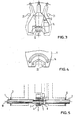
- FIG. 5 The type of tube connection to which the tool according to the invention applies is shown in FIG. 5.
- One of the tubes, 1, is provided with a nut 3, which is trapped behind a shoulder 4.
- the other tube 2 ends in a coaxial thread 5, which cooperates with the internal thread of the nut 3.
- Behind the thread 5, a lock nut 6 is welded to the tube 2, which serves to prevent the rotation of a tool when a tightening or loosening torque is applied to the nut 3.
- the contours of this tool are drawn by broken lines in this figure. We see that this tool extends between a washer 7 secured to the tube 1 at a distance from its end, and a washer 8 secured to the other tube 2 at a distance from its end.
- the lock nut 6 has a conventional hexagonal section, while the cylindrical surface of the nut 3 is provided with a plurality of grooves 9, regularly distributed and oriented parallel to the axis 6 of the two tubes 1 and 2.
- the outer surface of this nut 3 therefore has the shape of a toothed wheel, in which a corresponding key 12 meshes.
- FIGS. 1 and 2 The tool whose partial contours are indicated in fig. 5, is shown in detail in FIGS. 1 and 2, the view according to FIG. 5 corresponding to that of FIG. 2.
- This tool is mounted on a hollow frame 11.
- the key 12 cooperating with the nut 3 is mounted through a double-acting pneumatic cylinder 13 on a support 14.
- This support can tilt around the axis 10 of the tubes and it is guided in its tilting movement on the frame 11 by three screws 15, which are integral with the support 14 and which slide in a circular slot 16 formed in the frame 11.
- the tilting is controlled by reversible motor means constituted by two pneumatic cylinders 17 and 18, which face each other and whose pistons are connected by a common rod 19.
- the end of the tilting support 14 enters a notch 20 of the rod so that the movement of the rod 19 causes the support 14 to tilt about 30 ° around its tilting axis which coincides with the axis 10 of the tubes 1 and 2.
- FIG. 3 we see the support 14 with the key 12 and the actuator 13 in dotted lines in the two extreme positions and in continuous lines in its symmetrical position between these two extreme positions.
- the end of the piston stroke is on the bottom of cylinders 17 and 18.
- the shape of the key 12 is adapted to a sector of the cylindrical surface of the nut 3, as best seen in FIG. 3. This key 12 can be moved perpendicular to the axis 10 by the double-acting cylinder 13, which is mounted on the support 14.
- a counter key 22 capable of cooperating with the lock nut 6 is integral with the frame. As seen in fig. 4, this counter-key is located on the end of the frame 11.
- Bolts 21 join the end parts of the frame 11 and thus make the frame rigid.
- the elements described so far are sufficient to accomplish the desired function. It therefore suffices to apply the frame to the connection by engaging the lock key 22 on the lock nut 6, and to alternately control the drive means 18 and the actuator 13 according to a cycle such that the key 12 is lowered on the nut 3, the support 14 switches from one extreme position to the other (see fig. 3), the key is retracted, the support switches to its other extreme position using the drive means 17 and so on.
- means are provided for holding the tool on the connection during the tightening or loosening operation.
- These means consist of two pairs of arms 23, 24; 25, 26.
- the two arms of each pair are articulated on the frame each using a screwed axle 27, 28.
- a spring 29 spreads the ends of the arms of each pair, while two pneumatic cylinders 30 and 31 provide a force antagonistic to that of the spring 29.
- the arms extend at one end to the zone of the tubes, where they each terminate in a gripping element 32, 33; 34 (the gripping element of the arm 26 is not visible in the figures).
- the gripping elements are adapted to the outside diameter of the tubes 1 and 2.
- a remote manipulator brings the tool closer to the connection, while being guided by the washers 7 and 8.
- the jacks 30 and 31 of each pair of arms are de-energized and the gripping elements are consequently discarded.
- the counter-key 22 slides on the lock nut 6. If necessary, this is obtained by a slight rotation of the tool around the axis 10.
- the actuators 30 and 31 are controlled to close the arms and grip the two tubes on either side of the end of the tubes 1 and 2. Then, the double-acting actuator 13 is controlled to lower the key 12 on the nut 3.
- the tool does not require any permanent assistance by a remote manipulator; it takes up little space at the level of the tubes to be connected, which allows it to also be used in a compact bundle of tubes. Thanks to the distance between the notch 20 and the axis 10, it is possible to overcome high tightening torques using pneumatic cylinders 17 and 18.
- pneumatic motor means can be replaced by hydraulic or electric means.
Landscapes
- Engineering & Computer Science (AREA)
- Mechanical Engineering (AREA)
- Manipulator (AREA)
- Earth Drilling (AREA)
Claims (4)
Applications Claiming Priority (2)
| Application Number | Priority Date | Filing Date | Title |
|---|---|---|---|
| LU86210 | 1985-12-12 | ||
| LU86210A LU86210A1 (fr) | 1985-12-12 | 1985-12-12 | Outil de serrage/desserrage d'une connexion de tubes |
Publications (2)
| Publication Number | Publication Date |
|---|---|
| EP0226933A1 EP0226933A1 (de) | 1987-07-01 |
| EP0226933B1 true EP0226933B1 (de) | 1990-09-12 |
Family
ID=19730603
Family Applications (1)
| Application Number | Title | Priority Date | Filing Date |
|---|---|---|---|
| EP19860117102 Expired - Lifetime EP0226933B1 (de) | 1985-12-12 | 1986-12-09 | Werkzeug zum Anziehen und Lösen einer Rohrverbindung |
Country Status (5)
| Country | Link |
|---|---|
| EP (1) | EP0226933B1 (de) |
| DE (1) | DE3674165D1 (de) |
| ES (1) | ES2017623B3 (de) |
| GR (1) | GR3002518T3 (de) |
| LU (1) | LU86210A1 (de) |
Families Citing this family (3)
| Publication number | Priority date | Publication date | Assignee | Title |
|---|---|---|---|---|
| FR2655586B1 (fr) * | 1989-12-12 | 1995-01-20 | Renault | Appareil pour le raccordement par vissage de deux elements de tuyauterie. |
| GB9319346D0 (en) * | 1993-09-18 | 1993-11-03 | Fusion Group Plc | Pipe coupling |
| CN112388294A (zh) * | 2020-09-18 | 2021-02-23 | 海天塑机集团有限公司 | 一种扩口管接头拧紧机 |
Family Cites Families (4)
| Publication number | Priority date | Publication date | Assignee | Title |
|---|---|---|---|---|
| US3668949A (en) * | 1968-11-26 | 1972-06-13 | Deep Oil Technology Inc | Power wrench for making underwater pipe connections |
| DE2016352A1 (de) * | 1970-04-06 | 1971-10-28 | Cooper Industries, Inc., Houston, Tex. (V-StA.) | Rohrschlüssel |
| JPS5934782Y2 (ja) * | 1977-11-25 | 1984-09-26 | オ−エヌ工業株式会社 | 鋼管と継手の接続機構 |
| GB2046155B (en) * | 1979-04-11 | 1983-01-26 | Sumitomo Metal Ind | Method and apparatus for tightening nuts |
-
1985
- 1985-12-12 LU LU86210A patent/LU86210A1/fr unknown
-
1986
- 1986-12-09 DE DE8686117102T patent/DE3674165D1/de not_active Expired - Lifetime
- 1986-12-09 ES ES86117102T patent/ES2017623B3/es not_active Expired - Lifetime
- 1986-12-09 EP EP19860117102 patent/EP0226933B1/de not_active Expired - Lifetime
-
1990
- 1990-11-08 GR GR90400891T patent/GR3002518T3/el unknown
Also Published As
| Publication number | Publication date |
|---|---|
| GR3002518T3 (en) | 1993-01-25 |
| LU86210A1 (fr) | 1987-01-13 |
| DE3674165D1 (de) | 1990-10-18 |
| ES2017623B3 (es) | 1991-03-01 |
| EP0226933A1 (de) | 1987-07-01 |
Similar Documents
| Publication | Publication Date | Title |
|---|---|---|
| CA2128564C (fr) | Dispositif de nettoyage d'un cylindre | |
| FR2631868A1 (fr) | Dispositif et procede de vissage et de devissage d'un ecrou sur un element de liaison | |
| EP0254630A1 (de) | Verbindungsvorrichtung zur schnellen Demontage unter Last | |
| BE1005350A3 (fr) | Treuil a levier. | |
| CA1147581A (fr) | Dispositif pour appliquer un effort de deformation sur une piece | |
| EP0267109B1 (de) | Automatische Schweissroboterelektrodenwechselvorrichtung | |
| FR2717548A1 (fr) | Dispositif tendeur de goujons, notamment pour le boulonnage de couvercles et en particulier de cuves sous pression de réacteurs. | |
| EP0330551B1 (de) | Automatischer Objektgreifer | |
| EP0226933A1 (de) | Werkzeug zum Anziehen und Lösen einer Rohrverbindung | |
| EP0490798B1 (de) | Kran, insbesondere für die Handhabung | |
| EP0398815A1 (de) | Vorrichtung zum Ein- und Ausbauen von Spiralfedern | |
| FR2687343A1 (fr) | Dispositif de desserrage ou de serrage d'un ecrou visse sur un organe filete. | |
| FR2564019A1 (fr) | Pince d'alignement interne | |
| EP0243943B1 (de) | Automatisches Gerät zum Festziehen oder Lösen von Schraubbolzen einer Flanschverbindung zwischen zwei Rohrleitungen | |
| FR2746050A1 (fr) | Dispositif de decoupe longitudinale d'un tube | |
| FR2622138A1 (fr) | Outil de prehension notamment pour une fiche de connecteur de cable par telemanipulation | |
| FR2693674A1 (fr) | Accouplement automatique de changement d'outil. | |
| FR3110104A1 (fr) | dispositif d’interface pour bras rotatif robotisé , procédé de commande , dispositif d’intervention | |
| FR2747381A1 (fr) | Dispositif de transfert d'une charge par poussee et traction dans un meme plan | |
| FR2723545A1 (fr) | Poignee articulee pour la main de travail d'un robot | |
| EP0148679A1 (de) | Montagevorrichtung von einem Dreh- oder Fräswerkzeughalter zu einem Spindelträger einer Werkzeugmaschine | |
| BE1014382A5 (fr) | Mandrin de retenue pour le serrage d'un tube de verre. | |
| FR2766117A1 (fr) | Outil pour vissages multiples | |
| FR2750411A1 (fr) | Grue de chantier a pivot inferieur comprenant un chariot | |
| FR2707539A1 (fr) | Poinçonneuse manuelle. |
Legal Events
| Date | Code | Title | Description |
|---|---|---|---|
| PUAI | Public reference made under article 153(3) epc to a published international application that has entered the european phase |
Free format text: ORIGINAL CODE: 0009012 |
|
| AK | Designated contracting states |
Kind code of ref document: A1 Designated state(s): BE DE ES FR GB GR IT NL |
|
| 17P | Request for examination filed |
Effective date: 19871215 |
|
| 17Q | First examination report despatched |
Effective date: 19890503 |
|
| GRAA | (expected) grant |
Free format text: ORIGINAL CODE: 0009210 |
|
| AK | Designated contracting states |
Kind code of ref document: B1 Designated state(s): BE DE ES FR GB GR IT NL |
|
| PGFP | Annual fee paid to national office [announced via postgrant information from national office to epo] |
Ref country code: FR Payment date: 19901018 Year of fee payment: 5 |
|
| REF | Corresponds to: |
Ref document number: 3674165 Country of ref document: DE Date of ref document: 19901018 |
|
| ITF | It: translation for a ep patent filed | ||
| GBT | Gb: translation of ep patent filed (gb section 77(6)(a)/1977) | ||
| PGFP | Annual fee paid to national office [announced via postgrant information from national office to epo] |
Ref country code: BE Payment date: 19901205 Year of fee payment: 5 |
|
| PGFP | Annual fee paid to national office [announced via postgrant information from national office to epo] |
Ref country code: GR Payment date: 19901214 Year of fee payment: 5 |
|
| PGFP | Annual fee paid to national office [announced via postgrant information from national office to epo] |
Ref country code: DE Payment date: 19901218 Year of fee payment: 5 |
|
| PGFP | Annual fee paid to national office [announced via postgrant information from national office to epo] |
Ref country code: ES Payment date: 19901228 Year of fee payment: 5 |
|
| ITTA | It: last paid annual fee | ||
| PGFP | Annual fee paid to national office [announced via postgrant information from national office to epo] |
Ref country code: NL Payment date: 19901231 Year of fee payment: 5 |
|
| PLBE | No opposition filed within time limit |
Free format text: ORIGINAL CODE: 0009261 |
|
| STAA | Information on the status of an ep patent application or granted ep patent |
Free format text: STATUS: NO OPPOSITION FILED WITHIN TIME LIMIT |
|
| 26N | No opposition filed | ||
| PGFP | Annual fee paid to national office [announced via postgrant information from national office to epo] |
Ref country code: GB Payment date: 19911028 Year of fee payment: 6 |
|
| PG25 | Lapsed in a contracting state [announced via postgrant information from national office to epo] |
Ref country code: BE Effective date: 19911231 |
|
| BERE | Be: lapsed |
Owner name: COMMUNAUTE EUROPEENNE DE L'ENERGIE ATOMIQUE EURAT Effective date: 19911231 |
|
| PG25 | Lapsed in a contracting state [announced via postgrant information from national office to epo] |
Ref country code: GR Free format text: THE PATENT HAS BEEN ANNULLED BY A DECISION OF A NATIONAL AUTHORITY Effective date: 19920630 |
|
| PG25 | Lapsed in a contracting state [announced via postgrant information from national office to epo] |
Ref country code: NL Effective date: 19920701 |
|
| NLV4 | Nl: lapsed or anulled due to non-payment of the annual fee | ||
| PG25 | Lapsed in a contracting state [announced via postgrant information from national office to epo] |
Ref country code: FR Effective date: 19920831 |
|
| PG25 | Lapsed in a contracting state [announced via postgrant information from national office to epo] |
Ref country code: DE Effective date: 19920901 |
|
| REG | Reference to a national code |
Ref country code: GR Ref legal event code: FG4A Free format text: 3002518 |
|
| REG | Reference to a national code |
Ref country code: FR Ref legal event code: ST |
|
| PG25 | Lapsed in a contracting state [announced via postgrant information from national office to epo] |
Ref country code: GB Effective date: 19921209 |
|
| PG25 | Lapsed in a contracting state [announced via postgrant information from national office to epo] |
Ref country code: ES Free format text: LAPSE BECAUSE OF NON-PAYMENT OF DUE FEES Effective date: 19921210 |
|
| GBPC | Gb: european patent ceased through non-payment of renewal fee |
Effective date: 19921209 |
|
| REG | Reference to a national code |
Ref country code: GR Ref legal event code: MM2A Free format text: 3002518 |
|
| REG | Reference to a national code |
Ref country code: ES Ref legal event code: FD2A Effective date: 19930113 |
|
| PG25 | Lapsed in a contracting state [announced via postgrant information from national office to epo] |
Ref country code: IT Free format text: LAPSE BECAUSE OF NON-PAYMENT OF DUE FEES;WARNING: LAPSES OF ITALIAN PATENTS WITH EFFECTIVE DATE BEFORE 2007 MAY HAVE OCCURRED AT ANY TIME BEFORE 2007. THE CORRECT EFFECTIVE DATE MAY BE DIFFERENT FROM THE ONE RECORDED. Effective date: 20051209 |