EP0226790A2 - Unitary solid-state laser - Google Patents
Unitary solid-state laser Download PDFInfo
- Publication number
- EP0226790A2 EP0226790A2 EP86115576A EP86115576A EP0226790A2 EP 0226790 A2 EP0226790 A2 EP 0226790A2 EP 86115576 A EP86115576 A EP 86115576A EP 86115576 A EP86115576 A EP 86115576A EP 0226790 A2 EP0226790 A2 EP 0226790A2
- Authority
- EP
- European Patent Office
- Prior art keywords
- laser
- housing
- lamp
- laser medium
- medium
- Prior art date
- Legal status (The legal status is an assumption and is not a legal conclusion. Google has not performed a legal analysis and makes no representation as to the accuracy of the status listed.)
- Granted
Links
Images


Classifications
-
- H—ELECTRICITY
- H01—ELECTRIC ELEMENTS
- H01S—DEVICES USING THE PROCESS OF LIGHT AMPLIFICATION BY STIMULATED EMISSION OF RADIATION [LASER] TO AMPLIFY OR GENERATE LIGHT; DEVICES USING STIMULATED EMISSION OF ELECTROMAGNETIC RADIATION IN WAVE RANGES OTHER THAN OPTICAL
- H01S3/00—Lasers, i.e. devices using stimulated emission of electromagnetic radiation in the infrared, visible or ultraviolet wave range
- H01S3/02—Constructional details
- H01S3/025—Constructional details of solid state lasers, e.g. housings or mountings
-
- H—ELECTRICITY
- H01—ELECTRIC ELEMENTS
- H01S—DEVICES USING THE PROCESS OF LIGHT AMPLIFICATION BY STIMULATED EMISSION OF RADIATION [LASER] TO AMPLIFY OR GENERATE LIGHT; DEVICES USING STIMULATED EMISSION OF ELECTROMAGNETIC RADIATION IN WAVE RANGES OTHER THAN OPTICAL
- H01S3/00—Lasers, i.e. devices using stimulated emission of electromagnetic radiation in the infrared, visible or ultraviolet wave range
- H01S3/02—Constructional details
- H01S3/04—Arrangements for thermal management
- H01S3/042—Arrangements for thermal management for solid state lasers
-
- H—ELECTRICITY
- H01—ELECTRIC ELEMENTS
- H01S—DEVICES USING THE PROCESS OF LIGHT AMPLIFICATION BY STIMULATED EMISSION OF RADIATION [LASER] TO AMPLIFY OR GENERATE LIGHT; DEVICES USING STIMULATED EMISSION OF ELECTROMAGNETIC RADIATION IN WAVE RANGES OTHER THAN OPTICAL
- H01S3/00—Lasers, i.e. devices using stimulated emission of electromagnetic radiation in the infrared, visible or ultraviolet wave range
- H01S3/09—Processes or apparatus for excitation, e.g. pumping
- H01S3/091—Processes or apparatus for excitation, e.g. pumping using optical pumping
- H01S3/0915—Processes or apparatus for excitation, e.g. pumping using optical pumping by incoherent light
- H01S3/092—Processes or apparatus for excitation, e.g. pumping using optical pumping by incoherent light of flash lamp
- H01S3/093—Processes or apparatus for excitation, e.g. pumping using optical pumping by incoherent light of flash lamp focusing or directing the excitation energy into the active medium
-
- H—ELECTRICITY
- H01—ELECTRIC ELEMENTS
- H01S—DEVICES USING THE PROCESS OF LIGHT AMPLIFICATION BY STIMULATED EMISSION OF RADIATION [LASER] TO AMPLIFY OR GENERATE LIGHT; DEVICES USING STIMULATED EMISSION OF ELECTROMAGNETIC RADIATION IN WAVE RANGES OTHER THAN OPTICAL
- H01S3/00—Lasers, i.e. devices using stimulated emission of electromagnetic radiation in the infrared, visible or ultraviolet wave range
- H01S3/02—Constructional details
- H01S3/04—Arrangements for thermal management
- H01S3/0405—Conductive cooling, e.g. by heat sinks or thermo-electric elements
-
- H—ELECTRICITY
- H01—ELECTRIC ELEMENTS
- H01S—DEVICES USING THE PROCESS OF LIGHT AMPLIFICATION BY STIMULATED EMISSION OF RADIATION [LASER] TO AMPLIFY OR GENERATE LIGHT; DEVICES USING STIMULATED EMISSION OF ELECTROMAGNETIC RADIATION IN WAVE RANGES OTHER THAN OPTICAL
- H01S3/00—Lasers, i.e. devices using stimulated emission of electromagnetic radiation in the infrared, visible or ultraviolet wave range
- H01S3/02—Constructional details
- H01S3/04—Arrangements for thermal management
- H01S3/0407—Liquid cooling, e.g. by water
Definitions
- This invention relates to an optically-pumped solid-state laser whose laser medium and pump lamp are both embedded in a transparent solid housing.
- Radecki et al. in U. S. Patent 4,170,763, disclosed a conductively cooled laser pumping assembly in which the laser rod is supported by clamps that connect the ends of the rod to a heat conductive body.
- a unitary laser comprises
- the laser medium may have any suitable shape; e.g., rod, slab, etc.
- the medium e.g., rod, slab, etc.
- the laser rod and pump lamp are embedded in the housing, the laser of the present invention is simple, compact and rugged.
- embedded we mean that the rod and lamp are substantially surrounded by the housing on all sides, except possibly for the ends.
- the present invention provides a solid-state laser that has a unitary structure; i.e., the elements of the pump chamber - laser medium, pump lamp, and optical resonator - are a unit.
- the laser is simple, compact, and rugged.
- Fig. 1 depicts a separate envelope structure lla for lamp 11; however, housing 10 may serve as the lamp envelope.
- the pump lamp envelope lla may have a filter coating 16, to eliminate unwanted spectral components of the lamp output.
- a suitably chosen coating 16 will reflect back into the lamp those wavelengths (infrared and ultraviolet, for example) that do not efficiently excite the laser rod.
- a bonding agent 17 may surround the pump lamp and/or the laser rod. Greater efficiency can often be achieved by having an optional reflective coating or reflective element 18 around housing 10. Silver, of course, is a good reflecting material.
- F ig. 2 is a side view of an embodiment of the laser that includes radial cooling fins 20 that extend outward from housing 10.
- Fig. 3 in an end-on view, depicts an embodiment in which the cooling provided by fins 20 is augmented by a flow of coolant between the fins 20 and around the outside of housing 10.
- the coolant flow is directed through a shroud 30, which includes a baffle 31 that extends between the fins and deflects the coolant out of the shroud.
- Flowing a cooling fluid, such as air or water, over the outside of the housing places far fewer constraints on the system then does the conventional method of flowing fluid over the laser rod or lamp envelope.
- fluid cools the laser rod or lamp directly, its optical properties are important, and it must be stable despite being subjected to higher temperatures and radiation levels. Extreme cleanliness is essential, and any residue from the fluid can have a strong detrimental effect on laser performance.
- Fig 4 is a sectional view taken along the line 4-4 in Fig 1. It shows circular cross sections for housing 10, pump lamp 11, and laser rod 12. Also shown are filter coating 16 and reflective coating 18.
- the housing comprises two semicylindrical sections joined at surface 40. Such a "clam shell” structure facilitates removal and replacement of the pump lamp and laser rod and reduces thermal stresses. Alternatively, the housing may simply be of one piece, with cavities for the lamp and rod.
- Fig 5 is a sectional view of another embodiment of the present invention.
- the diameter of laser rod 12 is slightly smaller than that of its cavity in housing 10, leaving an annular gap 50.
- the laser rod may be supported by support 51, which optionally may include a conventional heater 52.
- the configuration shown in Fig 5, with heater 52, is particularly preferred when it is desired to operate the laser medium - alexandrite, for example - at an elevated temperature.
- the heater permits the user to bring the laser rod to an elevated temperature before lasing is begun, and gap 50 provides insulation to minimize the heat being conducted away by housing 10.
- an alexandrite laser having that structure can provide efficient (i.e., high-temperature) operation from the onset of lasing.
- the laser rod, pump lamp, and housing all heat up.
- laser media like alexandrite and emerald, whose output efficiency are not diminished at elevated temperatures, are preferred.
- high temperature operation would cause excessive stresses to build up if the thermal expansion coefficient of the housing is substantially different from that of the laser rod or pump lamp envelope materials.
- the laser rod and lamp envelope have thermal expansion coefficients similar to that of the housing. The thermal expansion coefficient difference that can be tolerated depends on the temperature at which the element (lamp or laser rod) will operate, the clearance between the element and the cavity wall, and the strength of the element and housing.
- lamp envelope and housing materials An important criterion for the choice of lamp envelope and housing materials is that they transmit in the wavelength region of the laser pump bands.
- materials that are suitable are certain glasses, fused silica, quartz, chrysoberyl, and sapphire.
- Sapphire and fused silica are preferred envelope materials, because they are suitable and are available commercially.
- Sapphire is a preferred housing material because of its superior thermal shock resistance.
- Glass moldings are also suitable for housings.
- the relevant parameters that guide the choice of materials in a particular instance - e.g., transmission spectra, thermal conductivity, and thermal expansion coefficient - are tabulated in reference works such as the American Institute of Physics Handbook, published by McGraw-Hill.
- the need to replace lamps and laser rods dictates a clam shell structure and no bonding agent.
- a bonding agent it is convenient to first provide it as a powder, surrounding the laser rod or lamp envelope in the housing cavity, and to then thermally fuse it.
- the criteria for bonding agents like those for the housing and lamp envelope, include high optical transmission in the spectral region of interest and good match of thermal expansion coefficient.
- the bonding agent should have a melting point that is low enough that the agent can be melted (and solidified) without damaging the laser medium, lamp, or housing.
- the bonding agent should not deteriorate during exposure to the heat and radiation generated by the lamp. Low melting glasses; certain polymers, such as silicone elastomers; and other similar materials, well known in the art, are suitable bonding agents.
Abstract
Description
- This invention relates to an optically-pumped solid-state laser whose laser medium and pump lamp are both embedded in a transparent solid housing.
- For many solid-state laser applications, a simple, compact, and rugged structure is desirable or even essential. In general, such a structure cannot be achieved if it is necessary to cool the laser medium with flowing gas or liquid. To avoid the need for fluid cooling, lasers using conduction cooling have been disclosed.
- Radecki et al., in U. S. Patent 4,170,763, disclosed a conductively cooled laser pumping assembly in which the laser rod is supported by clamps that connect the ends of the rod to a heat conductive body.
- Guch, in U. S. Patent 4,429,394, disclosed a conduction cooled solid-state laser that has a gap between a laser crystal and pump lamp mounted in a solid housing.
- In accordance with the present invention, a unitary laser comprises
- (a) a transparent, thermally-conductive solid housing,
- (b) a laser medium that has two opposite ends and is embedded in a first cavity in the housing,
- (c) a pump lamp for exciting the laser medium that is embedded in a second cavity in the housing, and
- (d) reflectors adjacent to the opposite ends of the laser medium that define an optical resonant cavity and support coherent radiation laser emitted by the laser medium. Preferably, the laser medium is alexandrite or emerald; the housing and lamp envelope are preferably sapphire.
- The laser medium may have any suitable shape; e.g., rod, slab, etc. For convenience, we refer to the medium as a "rod." Because the laser rod and pump lamp are embedded in the housing, the laser of the present invention is simple, compact and rugged. By "embedded" we mean that the rod and lamp are substantially surrounded by the housing on all sides, except possibly for the ends.
-
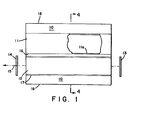
- Fig. 1 is a diagramatic illustration in partial cross section of a laser apparatus of the present invention.
- Fig. 2 is a side view of another embodiment of a laser of this invention.
- Fig. 3 is an end-on view, partially cut away, of a cooled laser of this invention.
- Fig. 4 is a cross-sectional view of the apparatus of Fig. 1.
- Fig. 5 is a cross-sectional view of another apparatus of the present invention.
- The present invention provides a solid-state laser that has a unitary structure; i.e., the elements of the pump chamber - laser medium, pump lamp, and optical resonator - are a unit. As a result of the unitary structure, the laser is simple, compact, and rugged.
- The construction of the pump chamber is shown schematically in Fig 1. Embedded in
transparent housing 10 ispump lamp 11 andlaser rod 12.Total reflector 13 andpartial reflector 14 are positioned along the axis oflaser medium 12. Lasing action is evidenced by the emission ofcoherent radiation 15. Note that Fig. 1 depicts a separate envelope structure lla forlamp 11; however,housing 10 may serve as the lamp envelope. Depending on the emission characteristics of the pump lamp, and the absorption characteristics of the laser rod, it may be advantageous that the pump lamp envelope lla have afilter coating 16, to eliminate unwanted spectral components of the lamp output. A suitably chosencoating 16 will reflect back into the lamp those wavelengths (infrared and ultraviolet, for example) that do not efficiently excite the laser rod. Furthermore, elimination of the ultraviolet component can prevent solarization of the laser rod. Optionally, abonding agent 17 may surround the pump lamp and/or the laser rod. Greater efficiency can often be achieved by having an optional reflective coating orreflective element 18 aroundhousing 10. Silver, of course, is a good reflecting material. - Fig. 2 is a side view of an embodiment of the laser that includes
radial cooling fins 20 that extend outward fromhousing 10. - Fig. 3, in an end-on view, depicts an embodiment in which the cooling provided by
fins 20 is augmented by a flow of coolant between thefins 20 and around the outside ofhousing 10. The coolant flow is directed through ashroud 30, which includes a baffle 31 that extends between the fins and deflects the coolant out of the shroud. Flowing a cooling fluid, such as air or water, over the outside of the housing places far fewer constraints on the system then does the conventional method of flowing fluid over the laser rod or lamp envelope. When fluid cools the laser rod or lamp directly, its optical properties are important, and it must be stable despite being subjected to higher temperatures and radiation levels. Extreme cleanliness is essential, and any residue from the fluid can have a strong detrimental effect on laser performance. - Fig 4 is a sectional view taken along the line 4-4 in Fig 1. It shows circular cross sections for
housing 10,pump lamp 11, andlaser rod 12. Also shown arefilter coating 16 andreflective coating 18. In the embodiment shown, the housing comprises two semicylindrical sections joined atsurface 40. Such a "clam shell" structure facilitates removal and replacement of the pump lamp and laser rod and reduces thermal stresses. Alternatively, the housing may simply be of one piece, with cavities for the lamp and rod. - Fig 5 is a sectional view of another embodiment of the present invention. In that embodiment, the diameter of
laser rod 12 is slightly smaller than that of its cavity inhousing 10, leaving anannular gap 50. Thus, conductive heat flow betweenrod 12 andhousing 10 is greatly reduced. The laser rod may be supported bysupport 51, which optionally may include aconventional heater 52. The configuration shown in Fig 5, withheater 52, is particularly preferred when it is desired to operate the laser medium - alexandrite, for example - at an elevated temperature. The heater permits the user to bring the laser rod to an elevated temperature before lasing is begun, andgap 50 provides insulation to minimize the heat being conducted away byhousing 10. Thus, an alexandrite laser having that structure can provide efficient (i.e., high-temperature) operation from the onset of lasing. - During laser operation, the laser rod, pump lamp, and housing all heat up. Thus, laser media like alexandrite and emerald, whose output efficiency are not diminished at elevated temperatures, are preferred. Unless there is a gap between the laser rod or lamp and the cavity that contains it, high temperature operation would cause excessive stresses to build up if the thermal expansion coefficient of the housing is substantially different from that of the laser rod or pump lamp envelope materials. Thus, for high power operation, it is preferred that the laser rod and lamp envelope have thermal expansion coefficients similar to that of the housing. The thermal expansion coefficient difference that can be tolerated depends on the temperature at which the element (lamp or laser rod) will operate, the clearance between the element and the cavity wall, and the strength of the element and housing.
- An important criterion for the choice of lamp envelope and housing materials is that they transmit in the wavelength region of the laser pump bands. Typical of materials that are suitable are certain glasses, fused silica, quartz, chrysoberyl, and sapphire. Sapphire and fused silica are preferred envelope materials, because they are suitable and are available commercially. Sapphire is a preferred housing material because of its superior thermal shock resistance. Glass moldings are also suitable for housings. The relevant parameters that guide the choice of materials in a particular instance - e.g., transmission spectra, thermal conductivity, and thermal expansion coefficient - are tabulated in reference works such as the American Institute of Physics Handbook, published by McGraw-Hill.
- If the laser is intended to have a long lifetime, then the need to replace lamps and laser rods dictates a clam shell structure and no bonding agent. If a bonding agent is used, it is convenient to first provide it as a powder, surrounding the laser rod or lamp envelope in the housing cavity, and to then thermally fuse it. The criteria for bonding agents, like those for the housing and lamp envelope, include high optical transmission in the spectral region of interest and good match of thermal expansion coefficient. In addition, the bonding agent should have a melting point that is low enough that the agent can be melted (and solidified) without damaging the laser medium, lamp, or housing. Finally, the bonding agent should not deteriorate during exposure to the heat and radiation generated by the lamp. Low melting glasses; certain polymers, such as silicone elastomers; and other similar materials, well known in the art, are suitable bonding agents.
Claims (10)
Applications Claiming Priority (2)
| Application Number | Priority Date | Filing Date | Title |
|---|---|---|---|
| US809606 | 1985-12-16 | ||
| US06/809,606 US4734913A (en) | 1985-12-16 | 1985-12-16 | Unitary solid-state laser |
Publications (3)
| Publication Number | Publication Date |
|---|---|
| EP0226790A2 true EP0226790A2 (en) | 1987-07-01 |
| EP0226790A3 EP0226790A3 (en) | 1988-03-16 |
| EP0226790B1 EP0226790B1 (en) | 1992-06-24 |
Family
ID=25201763
Family Applications (1)
| Application Number | Title | Priority Date | Filing Date |
|---|---|---|---|
| EP86115576A Expired EP0226790B1 (en) | 1985-12-16 | 1986-11-10 | Unitary solid-state laser |
Country Status (6)
| Country | Link |
|---|---|
| US (2) | US4734913A (en) |
| EP (1) | EP0226790B1 (en) |
| JP (1) | JPS62145886A (en) |
| AU (1) | AU591533B2 (en) |
| CA (1) | CA1285058C (en) |
| DE (1) | DE3685808T2 (en) |
Cited By (9)
| Publication number | Priority date | Publication date | Assignee | Title |
|---|---|---|---|---|
| WO1990000321A1 (en) * | 1988-06-27 | 1990-01-11 | Allied-Signal Inc. | Improved unitary solid-state laser |
| US4894837A (en) * | 1988-11-18 | 1990-01-16 | Spectra-Physics | Absorbing filter in pump cavity for control of beam quality |
| DE4303956A1 (en) * | 1993-02-10 | 1994-08-11 | Wolfgang Deutscher | laser |
| EP0694951A1 (en) * | 1994-07-20 | 1996-01-31 | Patent-Treuhand-Gesellschaft für elektrische Glühlampen mbH | Unit with lamp |
| EP0694950A1 (en) * | 1994-07-20 | 1996-01-31 | Patent-Treuhand-Gesellschaft für elektrische Glühlampen mbH | Lamp-reflector unit |
| WO1996009799A1 (en) * | 1994-09-29 | 1996-04-04 | Lokki S.A. | Pulsed-emission laser apparatus for medical use |
| WO1998006156A1 (en) * | 1996-08-07 | 1998-02-12 | Lumonics Inc. | Multiple element, folded beam laser |
| US5867518A (en) * | 1996-08-07 | 1999-02-02 | Lumonics Inc. | Multiple element laser pumping chamber |
| US5867519A (en) * | 1996-08-07 | 1999-02-02 | Lumonics Inc. | Multiple element, folded beam laser |
Families Citing this family (12)
| Publication number | Priority date | Publication date | Assignee | Title |
|---|---|---|---|---|
| US4734913A (en) * | 1985-12-16 | 1988-03-29 | Allied Corporation | Unitary solid-state laser |
| JPH02186685A (en) * | 1989-01-13 | 1990-07-20 | Tosoh Corp | Solid-state laser oscillation device |
| US4933946A (en) * | 1989-08-14 | 1990-06-12 | Allied-Signal Inc. | Conductively cooled solid-state slab laser |
| US4949346A (en) * | 1989-08-14 | 1990-08-14 | Allied-Signal Inc. | Conductively cooled, diode-pumped solid-state slab laser |
| JPH0410587A (en) * | 1990-04-27 | 1992-01-14 | Herutsu Kogyo Kk | Excitation of solid-state laser material |
| DE4022818A1 (en) * | 1990-07-18 | 1992-01-23 | Deutsche Forsch Luft Raumfahrt | SOLID LASER |
| US5331652A (en) * | 1993-03-22 | 1994-07-19 | Alliedsignal Inc. | Solid state laser having closed cycle gas cooled construction |
| JPH0766473A (en) * | 1993-08-26 | 1995-03-10 | Matsushita Electric Ind Co Ltd | Gas laser oscillator |
| JP2001117041A (en) * | 1999-10-19 | 2001-04-27 | Ricoh Co Ltd | Optical scanner and image forming device |
| US20040132228A1 (en) * | 2002-12-17 | 2004-07-08 | Honeywell International Inc. | Method and system for fabricating an OLED |
| US20040219390A1 (en) * | 2003-01-23 | 2004-11-04 | Honeywell International, Inc. | Benzoxazinone and quinazolinone derivatives |
| US20100054289A1 (en) | 2008-08-29 | 2010-03-04 | Cobolt Ab | Solid-state laser |
Citations (6)
| Publication number | Priority date | Publication date | Assignee | Title |
|---|---|---|---|---|
| US3471801A (en) * | 1964-12-31 | 1969-10-07 | Hughes Aircraft Co | Thermally controlled solid-state laser |
| GB1181021A (en) * | 1966-03-31 | 1970-02-11 | American Optical Corp | Improvements in or relating to laser Structures |
| US3676798A (en) * | 1969-10-13 | 1972-07-11 | Sperry Rand Corp | Cooling system for lasing media |
| GB1334009A (en) * | 1971-05-19 | 1973-10-17 | Gen Electric Co Ltd | Laser devices |
| US4429394A (en) * | 1981-11-09 | 1984-01-31 | Gte Products Corporation | Conduction cooled solid state laser |
| US4525842A (en) * | 1984-02-24 | 1985-06-25 | Myers John D | Laser device and method |
Family Cites Families (13)
| Publication number | Priority date | Publication date | Assignee | Title |
|---|---|---|---|---|
| US3455666A (en) * | 1966-05-06 | 1969-07-15 | American Optical Corp | Method of making laser components |
| US3500238A (en) * | 1967-03-06 | 1970-03-10 | American Optical Corp | Laser assemblies and the like |
| US3528030A (en) * | 1967-08-16 | 1970-09-08 | Honeywell Inc | Laser cavity comprising severable elements respectively carrying the laser rod and pumping source |
| US3626319A (en) * | 1970-04-14 | 1971-12-07 | Warner Lambert Pharmaceutical | Laser structures and the like |
| US3805186A (en) * | 1972-11-29 | 1974-04-16 | American Optical Corp | Unitary glass laser assembly |
| US4096450A (en) * | 1977-04-22 | 1978-06-20 | Hughes Aircraft Company | Conductively cooled flashlamp |
| US4170763A (en) * | 1978-01-03 | 1979-10-09 | Gte Sylvania Incorporated | Conductively cooled laser pumping assembly |
| US4199735A (en) * | 1978-07-03 | 1980-04-22 | Gte Sylvania Incorporated | Optical compensation for thermal lensing in conductively cooled laser rod |
| JPS5543266A (en) * | 1978-09-22 | 1980-03-27 | Chuji Saito | Power generator utilizing thermal difference between solar heat and cool water |
| US4601038A (en) * | 1982-01-18 | 1986-07-15 | Gte Government Systems Corporation | Conduction cooled solid state laser |
| JPS60239077A (en) * | 1984-05-11 | 1985-11-27 | Toshiba Corp | Solid-state laser oscillator |
| US4637028A (en) * | 1984-08-02 | 1987-01-13 | Hughes Aircraft Company | Conductively cooled laser rod |
| US4734913A (en) * | 1985-12-16 | 1988-03-29 | Allied Corporation | Unitary solid-state laser |
-
1985
- 1985-12-16 US US06/809,606 patent/US4734913A/en not_active Expired - Lifetime
-
1986
- 1986-11-10 EP EP86115576A patent/EP0226790B1/en not_active Expired
- 1986-11-10 DE DE8686115576T patent/DE3685808T2/en not_active Expired - Lifetime
- 1986-11-17 AU AU65312/86A patent/AU591533B2/en not_active Ceased
- 1986-12-12 CA CA000525127A patent/CA1285058C/en not_active Expired - Lifetime
- 1986-12-16 JP JP61299813A patent/JPS62145886A/en active Pending
-
1987
- 1987-06-16 US US07/062,940 patent/US4835786A/en not_active Expired - Lifetime
Patent Citations (6)
| Publication number | Priority date | Publication date | Assignee | Title |
|---|---|---|---|---|
| US3471801A (en) * | 1964-12-31 | 1969-10-07 | Hughes Aircraft Co | Thermally controlled solid-state laser |
| GB1181021A (en) * | 1966-03-31 | 1970-02-11 | American Optical Corp | Improvements in or relating to laser Structures |
| US3676798A (en) * | 1969-10-13 | 1972-07-11 | Sperry Rand Corp | Cooling system for lasing media |
| GB1334009A (en) * | 1971-05-19 | 1973-10-17 | Gen Electric Co Ltd | Laser devices |
| US4429394A (en) * | 1981-11-09 | 1984-01-31 | Gte Products Corporation | Conduction cooled solid state laser |
| US4525842A (en) * | 1984-02-24 | 1985-06-25 | Myers John D | Laser device and method |
Non-Patent Citations (2)
| Title |
|---|
| IEEE JOURNAL OF QUANTUM ELECTRONICS, vol. QE-5, no. 5, May 1969, pages 238-241, IEEE Pac., New York, US; I. LIBERMAN et al.: " Efficient Nd: YAG CW lasers using alkali additive lamps" * |
| JOURNAL OF APPLIED PHYSICS, vol. 33, no. 9, September 1962, pages 2910-2911, American Institute of Physics, New York, US; M.G. Holland: "Thermal conductivity of several optical maser materials" * |
Cited By (11)
| Publication number | Priority date | Publication date | Assignee | Title |
|---|---|---|---|---|
| WO1990000321A1 (en) * | 1988-06-27 | 1990-01-11 | Allied-Signal Inc. | Improved unitary solid-state laser |
| US4894837A (en) * | 1988-11-18 | 1990-01-16 | Spectra-Physics | Absorbing filter in pump cavity for control of beam quality |
| DE4303956A1 (en) * | 1993-02-10 | 1994-08-11 | Wolfgang Deutscher | laser |
| EP0694951A1 (en) * | 1994-07-20 | 1996-01-31 | Patent-Treuhand-Gesellschaft für elektrische Glühlampen mbH | Unit with lamp |
| EP0694950A1 (en) * | 1994-07-20 | 1996-01-31 | Patent-Treuhand-Gesellschaft für elektrische Glühlampen mbH | Lamp-reflector unit |
| WO1996009799A1 (en) * | 1994-09-29 | 1996-04-04 | Lokki S.A. | Pulsed-emission laser apparatus for medical use |
| FR2725315A1 (en) * | 1994-09-29 | 1996-04-05 | Lokki Sa | LASER APPARATUS WITH PULSED EMISSION, USED IN THE MEDICAL FIELD |
| WO1998006156A1 (en) * | 1996-08-07 | 1998-02-12 | Lumonics Inc. | Multiple element, folded beam laser |
| US5867518A (en) * | 1996-08-07 | 1999-02-02 | Lumonics Inc. | Multiple element laser pumping chamber |
| US5867519A (en) * | 1996-08-07 | 1999-02-02 | Lumonics Inc. | Multiple element, folded beam laser |
| EP0986150A1 (en) * | 1996-08-07 | 2000-03-15 | Lumonics Inc. | Multiple element, folded beam laser |
Also Published As
| Publication number | Publication date |
|---|---|
| JPS62145886A (en) | 1987-06-29 |
| CA1285058C (en) | 1991-06-18 |
| US4835786A (en) | 1989-05-30 |
| AU6531286A (en) | 1987-06-18 |
| AU591533B2 (en) | 1989-12-07 |
| EP0226790A3 (en) | 1988-03-16 |
| DE3685808D1 (en) | 1992-07-30 |
| US4734913A (en) | 1988-03-29 |
| DE3685808T2 (en) | 1992-12-24 |
| EP0226790B1 (en) | 1992-06-24 |
Similar Documents
| Publication | Publication Date | Title |
|---|---|---|
| US4734913A (en) | Unitary solid-state laser | |
| US4949346A (en) | Conductively cooled, diode-pumped solid-state slab laser | |
| US4096450A (en) | Conductively cooled flashlamp | |
| US5353293A (en) | Hybrid cooled ion laser | |
| EP0422122B1 (en) | Improved unitary solid-state laser | |
| JPS62262480A (en) | Laser device | |
| US8270443B2 (en) | Diode-pumped cavity | |
| US3437950A (en) | Ion laser having a metal tube shrink-fitted onto the ceramic discharge tube | |
| WO2002065596A2 (en) | Method and system for cooling a laser gain medium | |
| JPH05167143A (en) | Semiconductor laser equipment | |
| US6266352B1 (en) | Laser oscillation apparatus | |
| US4933946A (en) | Conductively cooled solid-state slab laser | |
| US5781573A (en) | High power solid state laser and method of increasing power using same | |
| US3582822A (en) | Laser flash tube | |
| EP0078941A1 (en) | Light-emitting-diode-pumped alexandrite laser | |
| CA2026006C (en) | Assembly for arranging optical components of a laser | |
| EP0431619A2 (en) | Laser device | |
| JPH1187813A (en) | Solid laser oscillator | |
| US3764935A (en) | Laser pump enclosure | |
| EP0510157A1 (en) | Laser apparatus | |
| JP4003726B2 (en) | Solid state laser apparatus and laser processing apparatus | |
| US5682399A (en) | Ion laser tube with a discharge tubule adopted for a high discharge current and a high laser output | |
| JP3951782B2 (en) | Semiconductor laser pumped solid state laser amplifier, semiconductor laser pumped solid state laser apparatus, and semiconductor laser cooling method in semiconductor laser pumped solid state laser amplifier | |
| JPS6310917B2 (en) | ||
| JPH0569963U (en) | Solid-state laser medium and solid-state laser device using the same |
Legal Events
| Date | Code | Title | Description |
|---|---|---|---|
| PUAI | Public reference made under article 153(3) epc to a published international application that has entered the european phase |
Free format text: ORIGINAL CODE: 0009012 |
|
| AK | Designated contracting states |
Kind code of ref document: A2 Designated state(s): DE FR GB NL |
|
| PUAL | Search report despatched |
Free format text: ORIGINAL CODE: 0009013 |
|
| AK | Designated contracting states |
Kind code of ref document: A3 Designated state(s): DE FR GB NL |
|
| 17P | Request for examination filed |
Effective date: 19880614 |
|
| 17Q | First examination report despatched |
Effective date: 19900406 |
|
| RAP1 | Party data changed (applicant data changed or rights of an application transferred) |
Owner name: ALLIED-SIGNAL INC. (A DELAWARE CORPORATION) |
|
| GRAA | (expected) grant |
Free format text: ORIGINAL CODE: 0009210 |
|
| AK | Designated contracting states |
Kind code of ref document: B1 Designated state(s): DE FR GB NL |
|
| REF | Corresponds to: |
Ref document number: 3685808 Country of ref document: DE Date of ref document: 19920730 |
|
| ET | Fr: translation filed | ||
| PLBE | No opposition filed within time limit |
Free format text: ORIGINAL CODE: 0009261 |
|
| STAA | Information on the status of an ep patent application or granted ep patent |
Free format text: STATUS: NO OPPOSITION FILED WITHIN TIME LIMIT |
|
| 26N | No opposition filed | ||
| PGFP | Annual fee paid to national office [announced via postgrant information from national office to epo] |
Ref country code: GB Payment date: 19951009 Year of fee payment: 10 |
|
| PGFP | Annual fee paid to national office [announced via postgrant information from national office to epo] |
Ref country code: FR Payment date: 19951116 Year of fee payment: 10 |
|
| PGFP | Annual fee paid to national office [announced via postgrant information from national office to epo] |
Ref country code: DE Payment date: 19951129 Year of fee payment: 10 |
|
| PGFP | Annual fee paid to national office [announced via postgrant information from national office to epo] |
Ref country code: NL Payment date: 19960924 Year of fee payment: 11 |
|
| PG25 | Lapsed in a contracting state [announced via postgrant information from national office to epo] |
Ref country code: GB Effective date: 19961110 |
|
| GBPC | Gb: european patent ceased through non-payment of renewal fee |
Effective date: 19961110 |
|
| PG25 | Lapsed in a contracting state [announced via postgrant information from national office to epo] |
Ref country code: FR Effective date: 19970731 |
|
| PG25 | Lapsed in a contracting state [announced via postgrant information from national office to epo] |
Ref country code: DE Effective date: 19970801 |
|
| REG | Reference to a national code |
Ref country code: FR Ref legal event code: ST |
|
| PG25 | Lapsed in a contracting state [announced via postgrant information from national office to epo] |
Ref country code: NL Free format text: LAPSE BECAUSE OF NON-PAYMENT OF DUE FEES Effective date: 19980601 |
|
| NLV4 | Nl: lapsed or anulled due to non-payment of the annual fee |
Effective date: 19980601 |