EP0225563B1 - Vorrichtung zum Abgeben von Fasern und Maschine zum Plazieren von Fasern - Google Patents
Vorrichtung zum Abgeben von Fasern und Maschine zum Plazieren von Fasern Download PDFInfo
- Publication number
- EP0225563B1 EP0225563B1 EP86116586A EP86116586A EP0225563B1 EP 0225563 B1 EP0225563 B1 EP 0225563B1 EP 86116586 A EP86116586 A EP 86116586A EP 86116586 A EP86116586 A EP 86116586A EP 0225563 B1 EP0225563 B1 EP 0225563B1
- Authority
- EP
- European Patent Office
- Prior art keywords
- fibre
- assembly
- slide
- placement head
- delivery assembly
- Prior art date
- Legal status (The legal status is an assumption and is not a legal conclusion. Google has not performed a legal analysis and makes no representation as to the accuracy of the status listed.)
- Expired - Lifetime
Links
Images


Classifications
-
- B—PERFORMING OPERATIONS; TRANSPORTING
- B29—WORKING OF PLASTICS; WORKING OF SUBSTANCES IN A PLASTIC STATE IN GENERAL
- B29C—SHAPING OR JOINING OF PLASTICS; SHAPING OF MATERIAL IN A PLASTIC STATE, NOT OTHERWISE PROVIDED FOR; AFTER-TREATMENT OF THE SHAPED PRODUCTS, e.g. REPAIRING
- B29C70/00—Shaping composites, i.e. plastics material comprising reinforcements, fillers or preformed parts, e.g. inserts
- B29C70/04—Shaping composites, i.e. plastics material comprising reinforcements, fillers or preformed parts, e.g. inserts comprising reinforcements only, e.g. self-reinforcing plastics
- B29C70/28—Shaping operations therefor
- B29C70/30—Shaping by lay-up, i.e. applying fibres, tape or broadsheet on a mould, former or core; Shaping by spray-up, i.e. spraying of fibres on a mould, former or core
- B29C70/38—Automated lay-up, e.g. using robots, laying filaments according to predetermined patterns
- B29C70/382—Automated fiber placement [AFP]
-
- B—PERFORMING OPERATIONS; TRANSPORTING
- B29—WORKING OF PLASTICS; WORKING OF SUBSTANCES IN A PLASTIC STATE IN GENERAL
- B29C—SHAPING OR JOINING OF PLASTICS; SHAPING OF MATERIAL IN A PLASTIC STATE, NOT OTHERWISE PROVIDED FOR; AFTER-TREATMENT OF THE SHAPED PRODUCTS, e.g. REPAIRING
- B29C53/00—Shaping by bending, folding, twisting, straightening or flattening; Apparatus therefor
- B29C53/56—Winding and joining, e.g. winding spirally
- B29C53/58—Winding and joining, e.g. winding spirally helically
- B29C53/60—Winding and joining, e.g. winding spirally helically using internal forming surfaces, e.g. mandrels
- B29C53/62—Winding and joining, e.g. winding spirally helically using internal forming surfaces, e.g. mandrels rotatable about the winding axis
- B29C53/66—Winding and joining, e.g. winding spirally helically using internal forming surfaces, e.g. mandrels rotatable about the winding axis with axially movable winding feed member, e.g. lathe type winding
-
- B—PERFORMING OPERATIONS; TRANSPORTING
- B29—WORKING OF PLASTICS; WORKING OF SUBSTANCES IN A PLASTIC STATE IN GENERAL
- B29C—SHAPING OR JOINING OF PLASTICS; SHAPING OF MATERIAL IN A PLASTIC STATE, NOT OTHERWISE PROVIDED FOR; AFTER-TREATMENT OF THE SHAPED PRODUCTS, e.g. REPAIRING
- B29C53/00—Shaping by bending, folding, twisting, straightening or flattening; Apparatus therefor
- B29C53/80—Component parts, details or accessories; Auxiliary operations
- B29C53/8008—Component parts, details or accessories; Auxiliary operations specially adapted for winding and joining
- B29C53/8016—Storing, feeding or applying winding materials, e.g. reels, thread guides, tensioners
-
- B—PERFORMING OPERATIONS; TRANSPORTING
- B65—CONVEYING; PACKING; STORING; HANDLING THIN OR FILAMENTARY MATERIAL
- B65H—HANDLING THIN OR FILAMENTARY MATERIAL, e.g. SHEETS, WEBS, CABLES
- B65H49/00—Unwinding or paying-out filamentary material; Supporting, storing or transporting packages from which filamentary material is to be withdrawn or paid-out
- B65H49/18—Methods or apparatus in which packages rotate
- B65H49/20—Package-supporting devices
- B65H49/32—Stands or frameworks
-
- B—PERFORMING OPERATIONS; TRANSPORTING
- B29—WORKING OF PLASTICS; WORKING OF SUBSTANCES IN A PLASTIC STATE IN GENERAL
- B29C—SHAPING OR JOINING OF PLASTICS; SHAPING OF MATERIAL IN A PLASTIC STATE, NOT OTHERWISE PROVIDED FOR; AFTER-TREATMENT OF THE SHAPED PRODUCTS, e.g. REPAIRING
- B29C70/00—Shaping composites, i.e. plastics material comprising reinforcements, fillers or preformed parts, e.g. inserts
- B29C70/04—Shaping composites, i.e. plastics material comprising reinforcements, fillers or preformed parts, e.g. inserts comprising reinforcements only, e.g. self-reinforcing plastics
- B29C70/28—Shaping operations therefor
- B29C70/54—Component parts, details or accessories; Auxiliary operations, e.g. feeding or storage of prepregs or SMC after impregnation or during ageing
- B29C70/545—Perforating, cutting or machining during or after moulding
-
- B—PERFORMING OPERATIONS; TRANSPORTING
- B65—CONVEYING; PACKING; STORING; HANDLING THIN OR FILAMENTARY MATERIAL
- B65H—HANDLING THIN OR FILAMENTARY MATERIAL, e.g. SHEETS, WEBS, CABLES
- B65H2701/00—Handled material; Storage means
- B65H2701/30—Handled filamentary material
- B65H2701/31—Textiles threads or artificial strands of filaments
-
- Y—GENERAL TAGGING OF NEW TECHNOLOGICAL DEVELOPMENTS; GENERAL TAGGING OF CROSS-SECTIONAL TECHNOLOGIES SPANNING OVER SEVERAL SECTIONS OF THE IPC; TECHNICAL SUBJECTS COVERED BY FORMER USPC CROSS-REFERENCE ART COLLECTIONS [XRACs] AND DIGESTS
- Y10—TECHNICAL SUBJECTS COVERED BY FORMER USPC
- Y10T—TECHNICAL SUBJECTS COVERED BY FORMER US CLASSIFICATION
- Y10T156/00—Adhesive bonding and miscellaneous chemical manufacture
- Y10T156/17—Surface bonding means and/or assemblymeans with work feeding or handling means
- Y10T156/1788—Work traversing type and/or means applying work to wall or static structure
Definitions
- the invention relates to fibre placement machines, and, in particular, relates to filament winding machines, wherein filaments or fibres are extended from a fibre creel assembly to a rotating form.
- Typical uses of filament winding machinery are to create reinforced cylindrical shapes for pressure vessels, rocket casings, etc.
- Certain prior art assemblies employ structures where the fibre support structure employs a vertically driven cross-slide, i.e. overhead to the horizontal rotating mandrel employed for work support, and the corresponding fibre creel assembly consisting of a plurality of fibre wound spools each threaded through a common payout eye, are carried overhead with the cross-slide.
- Other types of prior art assemblies employ a rotating work mandrel, in much the same manner as the cutting tool on a lathe.
- the horizontally-moving type machines are also provided with an overhead creel assembly to feed fibres to the payout eye.
- a fibre delivery assembly comprising an elongate, horizontally-extending support beam, a carriage supported by the support beam for movement relative thereto in a first direction parallel to the axis of the beam, a slide assembly supported by the carriage for movement relative thereto in a second direction substantially at right angles to said first direction, a fibre creel assembly and a fibre placement head.
- the fibre creel assembly is mounted on the carriage, and the fibre placement head is secured direct to the slide assembly, fibre strand being fed from the creel to the placement head through the slide assembly.
- Such a machine encounters difficulties when applying fibre to a large workpiece, and/or to a workpiece having a complicated three-dimensional shape.
- the fibre creel assembly is mounted on the slide assembly, and the fibre placement head is secured to the slide assembly through the intermediary of an articulable robot wrist whereby the placement head may be moved relative to the slide assembly about two mutually transverse axes, the fibre strands being fed from the creels directly to the placement head.
- the slide assembly may be mounted on the carriage through the intermediary of a unit by which the slide assembly may be moved vertically relative to the carriage, or the slide assembly may involve a part which may be moved pivotally about a substantially horizontal axis, specifically an axis extending parallel to the first direction, whereby limited substantially vertical movement of the payout means may be achieved.
- the robot wrist is capable of rotating the fibre payout means in three mutually inclined axis.
- the slide assembly is preferably elongate, with the fibre payout means mounted at one end portion, preferably that end portion which in use is adjacent to a workpiece to which fibre is to be applied, drive mechanism for the payout means being mounted at an opposite end portion of the slide assembly.
- the fibre payout means includes a cutter device to sever fibres drawn from the creel assembly, and mechanism to advance the severed end through an eye of the payout means.
- a fibre placement machine comprising a workpiece holding machine for supporting a workpiece, and a fibre delivery assembly of the kind set out in the last preceding paragraphs.
- the workpiece holding means comprises means for rotating the workpiece about a horizontal axis, and preferably a base upon which both the delivery assembly and the workpiece holding means are mounted, with the first direction of the fibre delivery means extending parallel to the axis of rotation of the workpiece holding means.
- the fibre placement machine 100 which is the preferred embodiment of this invention comprises a fibre placement assembly 300 and a workholding mechanism 200 mounted to the floor adjacent to the assembly 300, the floor 201 acting as a common base for the workholding mechanism 200 and the fibre placement assembly 300.
- the design is chosen for its modularity, but that in certain instances, the workholding mechanism 200 and fibre placement assembly 300 may be constructed on a unitary base structure, for example, a casting or weldment.
- the work holding mechanism 200 is not detailed, since it comprises any of a plurality of prior art units which have a drive box or boxes, capable of holding and (at desired intervals) rotating a plurality of work piece forms 11 a, 11 b.
- the machine 100 when the work is rotated, the machine 100 is referred to as a "filament winder". However, it will be obvious to those skilled in the art, that further description of the machine 100 provides for the placement of fibres on a variety of surfaces, for example: concave, convex and planar.
- the workpiece 11 a, 11 b forms are elongate, into the plane of the paper, and have their common axis 12 in a horizontal attitude (X-direction) to assist in loading and unloading the workpiece forms 11 a, 11b.
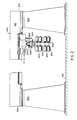
- the fibre placement assembly 300 comprises an overhead horizontal support beam 301, depicted in cross-section as being bifurcated, but it may be appreciated by those skilled in the art that the beam 301 may be hollow and box-like, or solid, and still function as a support unit.
- the support beams 301 is, in turn, supported at opposite ends 302, 303 (see Figure 2) by end support stanchions 304, 305 which are mounted on the floor 201.
- the cross-sectional view of Figure 1 shows that the front and back faces 306, 307 of the support beam 301 have parallel cylindrical bars 308 mounted thereto.
- the bearings 309 are carried in brackets 310 which are bolted to an underslung carriage 400- that is, passing beneath the support beam 301 - and thus, depending therefrom.
- the carriage 400 is provided with a drive box 401, drive motor 402, and rack and pinion (not shown) at the rear to propel the carriage 400 lengthwise down the support beam 301 in the "X"-direction.
- the carriage 400 supports a cross-slide 500, which has elongate, hollow housing 501, and is carried on a square way system 502 mounted in antifriction recirculating roller bearings 503, also available from the Thompson Co.
- the cross-slide 500 is oriented to move at 90° to the horizontal, X-direction axis 12 of the workpiece form holding mechanism 200.
- a drive motor 504 and ball screw 505 are provided to propel the cross-slide 500 normal to the support beam 301.
- the cross-slide housing 501 supports a fibre creel assembly 600 on its lowermost face, so that the fibre spools, or creels 601, are readily accessible to machine support personnel, for purposes of maintaining the integrity of the fibre systems and/or reloading the assembly 600.
- the fibre creels 601 are rotatable around horizontal shafts 602, extending outward from both sides of the creel assembly 600, parallel to the support beam 301.
- the motorised creel shafts 602 are held in bearings 603 and driven by a torque motor 604 so that fibre 13 or filament may be pulled from the creel 601 with a predetermined amount of fibre tension, and when slack occurs the torque motors 604 will back-drive to take up the slack, in a manner similar to that employed in composite tape-laying machines.
- a robotic wrist unit 700 is carried on the front face 506 of the cross-slide housing 501 and, whilst construction details have been omitted, the wrist unit may be purchased commercially from the Cincinnati Milacron Inc., the assignee of the present invention.
- the wrist unit is essentially the same as that depicted in U.S. 4,068,536 and the reader is referred to that patent for construction details.
- the end effector plate 701 is movable along triordinate axes, in accordance with internal drive gears and concentric tubes (not shown) which extend from the wrist unit 700 to the rear face 507 of the cross-slide housing 501, where the tubes are connected through a drive box 712 to a plurality of drive motors 713.
- the drive motors have the ability to drive ("roll") one, two, or three transversely-extending axes simultaneously to manipulate the end effector plate.
- the end effector plate 701 carries a tooling package, comprising a fibre payout unit 800, wherein a plurality of fibres 13 are pulled from the creel assembly 600, through a guide roller assembly 801, and ultimately, through a fibre payout eye 802.
- the fibre payout unit 800 has a compaction roller 803 which may be optionally employed at predetermined times to assist in impressing the fibres 13 against a workpiece from 11a, 11b. The operation of the payout unit will be described further in connection with Figures 6-11.
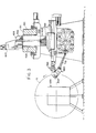
- FIGS 3 and 4 depict a second version of the present invention wherein a vertical, or "Y"-axis is established for moving the payout eye 802 in a vertical fashion relative to a workpiece form 11c.
- the support beam 302 is again depicted as being bifurcated, and a carriage 403, resembling an inverted “T", has a central carriage stem portion 404 extending therebetween to the topmost surface 311.
- the carriage stem portion has top and bottom open type ball bushings 405, and ball bars 406 are fitted to a vertically extending saddle unit 900 which is propelled by a ball screw drive 407 with respect to the carriage 403.
- the bottom section 901 of the saddle unit 900 serves to carry the cross-slide unit 500 in the manner depicted in Figure 1.
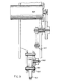
- FIG. 5 illustrates the creel assembly with the sideways-extending creels 601 of fibre, with individual fibres 13 being pulled through the guide roller assembly 801, and ultimately through a comb unit 804 to the fibre payout eye 802.
- Figures 6-11 refer to the fibre payout unit 800, and in the partial section of Figure 6, the unit 800 is shown mounted to the end effector plate of the wrist unit.
- the end effector 701 is rotatable around a first oblique roll axis 702 converging with the central longitudinal Z-axis of the cross-slide 500.
- the wrist unit 700 is also rotatable around the cross-slide unit Z-axis and the assembly is also rotatable around a second oblique axis 703 passing through the point of convergence 704 of the first axis 702 with the horizontal Z-axis.
- the side wall 805 of the payout unit 800 supports a torque motor 806 driving through a pair of sprockets 807, 808 to a pinion 809 in mesh with a rotatable gear sector 810.
- the gear sector 810 serves to rotate the guide roller assembly 801 through a drive shaft 811.
- the fibres are guided across short and long crossed rollers 812, 813; through internal camb unit 804, through a restart mechanism 830, past a fibre cutter device 832, and through the payout eye 802.
- the payout eye 802 is normally the last element in the unit 800, but, as depicted in Figure 6, compacting roller 803 has been actuated to impress fibres 13 on a laydown surface, similar to the technique utilised in some composite tape laying machine.
- the compacting roller 803 is carried on a pivot plate 814 supported on a pivot pin 815 extending between the walls 805, 816 of the payout unit 800.
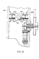
- the plate 814 is moved between retracted and advanced (shown solid) positions by a clevis-mounted cylinder 817 which is supported on side trunions 818 in bearings 819 located within the side walls 805, 816 of the payout unit 800 (see Figure 10).
- Figure 9 shows the bearing support system 820 for the compaction roller 803 with the roller shaft 821 geared to an output shaft 822 which is connected through a timing pulley/belt system 823 to a motor 824 for rotating compaction roller 803 when a new fibre placement is begun to achieve adhesion of the free ends of the fibres to the surface with minimal fibre slippage.
- the fibre cutter device 832 and the restart mechanism 830 provide the means for automatically controlling placement of fibres with discontinuities in the fibres.
- the cutter knife 834 shown leaving first free ends to be placed on the surface by further advance of the payout unit 800 and second free ends to begin a new fibre placement. Fibre placement beginning with the second free ends is started by use of the restart mechanism 830.
- the fibres are grasped above the second free ends thereof between grip belt 825 and 826 by advancement of the belt roller housings 838 and 840 effected by cylinders 842 and 844.
- the grip belts 825 and 826 are seen in end view in the belt roller housings 838 and 840 in Figure 11.
- the grip belts 825 and 826 are advanced over their respective rollers by the motor 846 through the drive train of pulleys and belts depicted in Figure 6.
- the second ends of the fibres are thus advanced through the payout eye 802 to the nip between the compaction roller 803 and the surface.
- cylinders 842 and 844 retract belt roller housings 838 and 840 to release the fibres from the grasp of grip belts 825 and 826 to permit fibre placement to continue.
- the cross-slide 312 comprises two members: a linearly movable subslide 312a supporting a pivotable housing 312b.
- the housing 312b has a pair of trunions 313 near its rearmost end which are supported in side bearings 314 within the sub- slide 312a.
- the front of the subslide 312a has a linear actuator 315 (for example, the ball screw and nut system shown), clevis-mounted at the ends to a subslide bracket 316 and pivot housing 312b.
- a substantially vertical movement of the payout eye 802 may be achieved without the necessity of providing a vertical slideway system.
- the small horizontal movement seen at the payout eye 802 while the pivot housing 312b is moved may be compensated-out by slight sub- slide movement effected by a machine control (not shown).
- the preferred embodiment utilises a robotic wrist unit 700 having three axes of roll movement
- various sub-movements may be utilised and found within other, simpler robot wrists.
- the payout eye 802 may be manipulated by a wrist having only smaller vertical movement.
- the robotic wrist may also be utilised to compensate for small unwanted components of movement, for example, Z-axis movement resulting from pivot motion of the pivotable housing 312b.
Claims (11)
dadurch gekennzeichnet, daß:
Applications Claiming Priority (2)
| Application Number | Priority Date | Filing Date | Title |
|---|---|---|---|
| US06/808,911 US4907754A (en) | 1985-12-13 | 1985-12-13 | Fiber placement machine |
| US808911 | 2001-03-14 |
Publications (3)
| Publication Number | Publication Date |
|---|---|
| EP0225563A2 EP0225563A2 (de) | 1987-06-16 |
| EP0225563A3 EP0225563A3 (en) | 1988-03-02 |
| EP0225563B1 true EP0225563B1 (de) | 1990-11-07 |
Family
ID=25200093
Family Applications (1)
| Application Number | Title | Priority Date | Filing Date |
|---|---|---|---|
| EP86116586A Expired - Lifetime EP0225563B1 (de) | 1985-12-13 | 1986-11-28 | Vorrichtung zum Abgeben von Fasern und Maschine zum Plazieren von Fasern |
Country Status (4)
| Country | Link |
|---|---|
| US (1) | US4907754A (de) |
| EP (1) | EP0225563B1 (de) |
| JP (1) | JPH0764473B2 (de) |
| DE (1) | DE3675507D1 (de) |
Families Citing this family (45)
| Publication number | Priority date | Publication date | Assignee | Title |
|---|---|---|---|---|
| US5022952A (en) * | 1985-12-13 | 1991-06-11 | Cincinnati Milacron Inc. | Fiber placement machine |
| DE3766525D1 (de) * | 1986-04-07 | 1991-01-17 | Hercules Inc | Faden-abwickelvorrichtung. |
| EP0355308B1 (de) * | 1988-08-25 | 1993-09-22 | Cincinnati Milacron Inc. | Auflegevorrichtung für Fasern |
| US5045147A (en) * | 1988-11-23 | 1991-09-03 | Hercules Incorporated | Filament winding system |
| CA2057201C (en) * | 1990-12-19 | 1998-05-19 | Vernon M. Benson | Multiple axes fiber placement machine |
| US5273602A (en) * | 1990-12-19 | 1993-12-28 | Hercules Incorporated | Ribbonizing method for selectively heating a respective one of a plurality of fiber tows |
| CA2057222C (en) * | 1990-12-19 | 1998-05-19 | Keith G. Shupe | Fiber placement delivery system |
| CA2057225C (en) * | 1990-12-19 | 1994-09-27 | John A. Johnson | Band fiber forming and placement delivery head |
| US5223072A (en) * | 1991-05-24 | 1993-06-29 | Cincinnati Milacron, Inc. | Intelligent servo-controlled fiber placement machine tensioner |
| DE69213875D1 (de) | 1991-07-31 | 1996-10-24 | Hercules Inc | In-situ-Aushärtungssystem |
| US5766357A (en) * | 1996-09-19 | 1998-06-16 | Alliant Techsystems Inc. | Apparatus for fiber impregnation |
| US5810271A (en) * | 1997-08-04 | 1998-09-22 | Rjs Corporation | Roller board and method for loading the same |
| US5979531A (en) * | 1997-10-01 | 1999-11-09 | Mcdonnell Douglas Corporation | Bi-directional fiber placement head |
| US6050315A (en) | 1998-04-30 | 2000-04-18 | Alliant Techsystems Inc. | Method and apparatus for producing fiber reinforced structures |
| US6026883A (en) * | 1998-04-30 | 2000-02-22 | Alliant Techsystems, Inc. | Self-contained apparatus for fiber element placement |
| US6149851A (en) * | 1998-04-30 | 2000-11-21 | Alliant Techsystems Inc. | Tooling apparatus and method for producing grid stiffened fiber reinforced structures |
| US6112792A (en) * | 1998-11-19 | 2000-09-05 | The Boeing Company | Fiber placement mid-span redirect |
| US6179945B1 (en) | 1998-12-30 | 2001-01-30 | Owens Corning Fiberglas Technology, Inc. | Process for filament winding composite workpieces |
| US6544367B1 (en) | 1999-02-01 | 2003-04-08 | Alliant Techsystems Inc. | Overwrap tape end-effector for fiber placement/winding machines |
| US6491773B1 (en) | 2000-01-24 | 2002-12-10 | Alliant Techsystems Inc. | Position-controlled tensioner system |
| CN1191981C (zh) * | 2000-06-13 | 2005-03-09 | 爱瑟瑞德合成物加拿大公司 | 将纤维件置入模型的通道的方法及纤维置入头 |
| AU2002216657A1 (en) | 2000-11-15 | 2002-05-27 | Toyota Motor Sales, U.S.A., Inc. | One-piece closed-shape structure and method of forming same |
| US6557702B1 (en) * | 2001-10-31 | 2003-05-06 | Skb Corporation | Golf club travel bag |
| US7226559B2 (en) * | 2000-12-08 | 2007-06-05 | Toyota Motor Sales, U.S.A., Inc. | Method for molding structures |
| WO2002070232A1 (en) * | 2001-03-02 | 2002-09-12 | Toyota Motor Sales, Usa, Inc. | Filament winding apparatus and methods of winding filament |
| ES2212878B1 (es) * | 2002-03-05 | 2005-07-16 | Manuel Torres Martinez | Cabezal multiaplicador de tiras de fibra. |
| US7559332B2 (en) * | 2002-07-02 | 2009-07-14 | Toyota Motor Sales U.S.A., Inc. | Media removal apparatus and methods of removing media |
| US7101452B2 (en) * | 2002-07-19 | 2006-09-05 | Toyota Motor Sales Usa, Inc. | Methods of debonding a composite tooling |
| US7217380B2 (en) * | 2002-07-22 | 2007-05-15 | Toyota Motor Sales, Usa, Inc. | Vibration apparatus and methods of vibration |
| US7101453B2 (en) * | 2002-09-04 | 2006-09-05 | Toyota Motor Sales U.S.A., Inc. | Pre-filled contained media volumes and methods of media filling using pre-filled contained media volumes |
| US7294220B2 (en) * | 2003-10-16 | 2007-11-13 | Toyota Motor Sales, U.S.A., Inc. | Methods of stabilizing and/or sealing core material and stabilized and/or sealed core material |
| US7353853B2 (en) * | 2005-05-03 | 2008-04-08 | Cincinnati Machine, Llc | Fiber placement machine |
| US7849903B2 (en) * | 2007-06-06 | 2010-12-14 | Cincinnati Machine, Llc | Motorized cut and feed head |
| FR2940175B1 (fr) | 2008-12-19 | 2013-04-12 | Hexcel Reinforcements | Tete pour l'application de fils de renfort sur une surface de depose |
| US20100200168A1 (en) * | 2009-02-06 | 2010-08-12 | Ingersoll Machine Tools, Inc. | Fiber delivery apparatus and system having a creel and fiber placement head sans fiber redirect |
| US20110117231A1 (en) * | 2009-11-19 | 2011-05-19 | General Electric Company | Fiber placement system and method with inline infusion and cooling |
| US8954180B2 (en) | 2010-08-06 | 2015-02-10 | Ingersoll Machine Tools, Inc. | Manufacturing process and apparatus having an interchangeable machine tool head with integrated control |
| US9126374B2 (en) | 2010-09-28 | 2015-09-08 | Russell B. Hanson | Iso-grid composite component |
| US8534338B2 (en) | 2010-10-15 | 2013-09-17 | Ingersoll Machine Tools, Inc. | Fiber delivery apparatus and system having a creel and fiber placement head with polar axis of rotation |
| US8911579B2 (en) | 2011-07-01 | 2014-12-16 | Adc Acquisition Company | Fluid medium non-contact consolidation |
| US8997818B2 (en) * | 2013-02-27 | 2015-04-07 | Fives Machining Systems, Inc. | Device for fabricating a composite structure |
| KR101422129B1 (ko) * | 2013-05-16 | 2014-07-22 | 재단법인 중소조선연구원 | 회전식 몰드를 이용한 고속 적층성형 장치 |
| KR101918353B1 (ko) * | 2016-10-04 | 2018-11-14 | 현대자동차주식회사 | 섬유토우 적층장치 |
| US10987871B2 (en) | 2017-03-08 | 2021-04-27 | General Atomics Aeronautical Systems, Inc. | Systems and methods for tool-less manufacturing of thermoplastic parts |
| US11478997B2 (en) * | 2019-09-12 | 2022-10-25 | The Boeing Company | Automated fiber placement system and associated method |
Family Cites Families (9)
| Publication number | Priority date | Publication date | Assignee | Title |
|---|---|---|---|---|
| US3146962A (en) * | 1961-03-15 | 1964-09-01 | Ici Ltd | Filament winding machine for mandrel having dome-shaped ends |
| US3378427A (en) * | 1964-06-26 | 1968-04-16 | Smith Corp A O | Apparatus for winding articles |
| US3363849A (en) * | 1965-02-10 | 1968-01-16 | Mcclean Anderson Inc | Filament winding apparatus |
| US3393918A (en) * | 1965-04-05 | 1968-07-23 | Styka Andrew | Filament wound resin reinforced structure and method |
| US3616078A (en) * | 1969-01-23 | 1971-10-26 | Rohr Corp | Apparatus and method for wrapping tape on multisided articles |
| US3853282A (en) * | 1972-12-06 | 1974-12-10 | Beloit Corp | Tensioning device |
| US4068536A (en) * | 1976-12-23 | 1978-01-17 | Cincinnati Milacron Inc. | Manipulator |
| US4324607A (en) * | 1978-05-24 | 1982-04-13 | Bandag Incorporated | Hose building machine |
| DE2933709A1 (de) * | 1979-08-21 | 1981-03-26 | Vereinigung zur Förderung des Instituts für Kunststoffverarbeitung in Industrie und Handwerk an der Rhein.-Westf. Technischen Hochschule Aachen eV, 52062 Aachen | Einrichtung zum fuehren eines wickelbandes an einer maschine zur herstellung von wickelkoerpern |
-
1985
- 1985-12-13 US US06/808,911 patent/US4907754A/en not_active Expired - Lifetime
-
1986
- 1986-11-28 DE DE8686116586T patent/DE3675507D1/de not_active Expired - Fee Related
- 1986-11-28 EP EP86116586A patent/EP0225563B1/de not_active Expired - Lifetime
- 1986-12-09 JP JP61293337A patent/JPH0764473B2/ja not_active Expired - Fee Related
Also Published As
| Publication number | Publication date |
|---|---|
| US4907754A (en) | 1990-03-13 |
| EP0225563A2 (de) | 1987-06-16 |
| JPH0764473B2 (ja) | 1995-07-12 |
| JPS62140977A (ja) | 1987-06-24 |
| DE3675507D1 (de) | 1990-12-13 |
| EP0225563A3 (en) | 1988-03-02 |
Similar Documents
| Publication | Publication Date | Title |
|---|---|---|
| EP0225563B1 (de) | Vorrichtung zum Abgeben von Fasern und Maschine zum Plazieren von Fasern | |
| US5022952A (en) | Fiber placement machine | |
| US5110395A (en) | Fiber placement head | |
| US4877193A (en) | Redirect roller apparatus for fiber placement machine | |
| US8151854B2 (en) | Fiber placement machine platform system having interchangeable head and creel assemblies | |
| US6096164A (en) | Multiple axes fiber placement machine | |
| EP1149039B1 (de) | Bandwickelendeffektor für faserauflege- oder -wickelmaschinen | |
| EP1658172B1 (de) | Automatisierte mehrkopf-verbundstofflaminiermaschine zur herstellung von grossen zylinderquerschnittsteilen | |
| US5431749A (en) | Tape laying head with curved tape laying capability and improved adaptive steering | |
| US4872619A (en) | Serco driven redirect roller apparatus for fiber placement machine | |
| US8210086B2 (en) | Braided reinforcement for aircraft fuselage frames and method of producing the same | |
| KR102437224B1 (ko) | 섬유 복합 구성품을 제조하기 위한 시스템 | |
| KR102414066B1 (ko) | 섬유 레잉 기계 | |
| JPH04341829A (ja) | デリバリーヘッド | |
| KR950002513B1 (ko) | 웨브의 분할권취장치 | |
| US5145543A (en) | Combination filament winding and tape laying apparatus and method for making and using the same | |
| DE3843488C2 (de) | ||
| JPS62290683A (ja) | フィラメント巻取り装置 | |
| EP0355308B1 (de) | Auflegevorrichtung für Fasern | |
| EP0823326B1 (de) | Verfahren und Vorrichtung zum fortlaufend multidirektional Laminieren | |
| JPH04336944A (ja) | 板材加工機 | |
| JP2002134345A (ja) | 一括搬送巻線装置および一括搬送巻線方法 | |
| KR20240037242A (ko) | 다수의 권취 헤드를 갖는 회전 지지체를 구비한 필라멘트 권취기 | |
| RU2056292C1 (ru) | Устройство для изготовления изделий из слоистых пластиков | |
| JPH04288939A (ja) | コイルばねの製造装置 |
Legal Events
| Date | Code | Title | Description |
|---|---|---|---|
| PUAI | Public reference made under article 153(3) epc to a published international application that has entered the european phase |
Free format text: ORIGINAL CODE: 0009012 |
|
| AK | Designated contracting states |
Kind code of ref document: A2 Designated state(s): DE FR GB IT |
|
| PUAL | Search report despatched |
Free format text: ORIGINAL CODE: 0009013 |
|
| AK | Designated contracting states |
Kind code of ref document: A3 Designated state(s): DE FR GB IT |
|
| 17P | Request for examination filed |
Effective date: 19880524 |
|
| 17Q | First examination report despatched |
Effective date: 19890405 |
|
| GRAA | (expected) grant |
Free format text: ORIGINAL CODE: 0009210 |
|
| AK | Designated contracting states |
Kind code of ref document: B1 Designated state(s): DE FR GB IT |
|
| ITF | It: translation for a ep patent filed |
Owner name: SOCIETA' ITALIANA BREVETTI S.P.A. |
|
| REF | Corresponds to: |
Ref document number: 3675507 Country of ref document: DE Date of ref document: 19901213 |
|
| ET | Fr: translation filed | ||
| PLBE | No opposition filed within time limit |
Free format text: ORIGINAL CODE: 0009261 |
|
| STAA | Information on the status of an ep patent application or granted ep patent |
Free format text: STATUS: NO OPPOSITION FILED WITHIN TIME LIMIT |
|
| 26N | No opposition filed | ||
| ITTA | It: last paid annual fee | ||
| PGFP | Annual fee paid to national office [announced via postgrant information from national office to epo] |
Ref country code: GB Payment date: 19931118 Year of fee payment: 8 |
|
| PGFP | Annual fee paid to national office [announced via postgrant information from national office to epo] |
Ref country code: DE Payment date: 19931123 Year of fee payment: 8 |
|
| PG25 | Lapsed in a contracting state [announced via postgrant information from national office to epo] |
Ref country code: GB Effective date: 19941128 |
|
| GBPC | Gb: european patent ceased through non-payment of renewal fee |
Effective date: 19941128 |
|
| PG25 | Lapsed in a contracting state [announced via postgrant information from national office to epo] |
Ref country code: DE Effective date: 19950801 |
|
| PGFP | Annual fee paid to national office [announced via postgrant information from national office to epo] |
Ref country code: FR Payment date: 19951109 Year of fee payment: 10 |
|
| PG25 | Lapsed in a contracting state [announced via postgrant information from national office to epo] |
Ref country code: FR Effective date: 19970731 |
|
| REG | Reference to a national code |
Ref country code: FR Ref legal event code: ST |
|
| PG25 | Lapsed in a contracting state [announced via postgrant information from national office to epo] |
Ref country code: IT Free format text: LAPSE BECAUSE OF NON-PAYMENT OF DUE FEES;WARNING: LAPSES OF ITALIAN PATENTS WITH EFFECTIVE DATE BEFORE 2007 MAY HAVE OCCURRED AT ANY TIME BEFORE 2007. THE CORRECT EFFECTIVE DATE MAY BE DIFFERENT FROM THE ONE RECORDED. Effective date: 20051128 |