EP0225138A1 - Heat conducting device - Google Patents
Heat conducting device Download PDFInfo
- Publication number
- EP0225138A1 EP0225138A1 EP86309112A EP86309112A EP0225138A1 EP 0225138 A1 EP0225138 A1 EP 0225138A1 EP 86309112 A EP86309112 A EP 86309112A EP 86309112 A EP86309112 A EP 86309112A EP 0225138 A1 EP0225138 A1 EP 0225138A1
- Authority
- EP
- European Patent Office
- Prior art keywords
- cold
- finger
- heat
- members
- heat conducting
- Prior art date
- Legal status (The legal status is an assumption and is not a legal conclusion. Google has not performed a legal analysis and makes no representation as to the accuracy of the status listed.)
- Withdrawn
Links
Images
Classifications
-
- F—MECHANICAL ENGINEERING; LIGHTING; HEATING; WEAPONS; BLASTING
- F25—REFRIGERATION OR COOLING; COMBINED HEATING AND REFRIGERATION SYSTEMS; HEAT PUMP SYSTEMS; MANUFACTURE OR STORAGE OF ICE; LIQUEFACTION SOLIDIFICATION OF GASES
- F25D—REFRIGERATORS; COLD ROOMS; ICE-BOXES; COOLING OR FREEZING APPARATUS NOT OTHERWISE PROVIDED FOR
- F25D19/00—Arrangement or mounting of refrigeration units with respect to devices or objects to be refrigerated, e.g. infrared detectors
- F25D19/006—Thermal coupling structure or interface
Definitions
- This invention relates to a device for conducting heat from one to another of two members between which the spacing may vary, for example, because of tolerances in manufacture of the apparatus comprising the two members and conducting assembly and/or because of relative movement of the two members during operation of the apparatus. More particularly, but not exclusively, the invention is concerned with heat conduction at very low temperatures in cryogenic apparatus, for example a Stirling-cycle cooling engine.
- Stirling-cycle cooling engines have potential benefits in the field of aerospace for cooling optical sensor components especially infra-red sensor components down to the very low temperatures at which they operate best.
- a relevant part is the device by which heat is conducted from the substrate or substrate support member of the optical sensor component which is to be cooled to the cold end of the Stirling-cycle engine cold finger (the cold finger is the element, usually elongate, within which the working fluid displacer moves and along which heat is transferred to cool one end and warm the other).
- the distance between the component and the cold finger may vary due to manufacturing tolerances from one to another engine unit, or it may vary with time within the same unit due say to expansion and contraction. Meanwhile highly efficient transfer between the two elements must be guaranteed. It has been proposed to fit between the component and cold finger a pad made of wire wool, somewhat like a small household scouring pad but of course made of material with high heat conductivity.
- the object of this invention is to provide a heat conducting device for use in the described situation which gives efficient transfer of heat without requiring any post-production adjustment. Accordingly, we provide between two members between which heat is to be transferred one or more resilient strips each made up of a plurality of thin laminae of thermally conductive metal, for example copper and the laminae being joined together at two spaced positions at which they are also fixed to respective ones of the members.
- the fixing of the laminae together and to the members may be by vacuum brazing.
- the or each strip is U-shaped, the two fixing position being at the ends of the limbs of the U-shape.
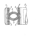
- the engine comprises a cold-finger 2, namely a hollow elongate cylinder containing a working fluid such as helium and a displacer (not shown) which is reciprocated within the cylinder while at the same time pressure variations are engendered within the working fluid, say by a separate piston and cylinder arrangement (not shown).
- a working fluid such as helium
- a displacer (not shown) which is reciprocated within the cylinder while at the same time pressure variations are engendered within the working fluid, say by a separate piston and cylinder arrangement (not shown).
- a separate piston and cylinder arrangement not shown.
- heat is drawn away from the illustrated cold end of the cold finger.
- the theory of Stirling-cycle cooling engines is well-known - further information about design and operation can be found in many publications.
- a gold-plated member 1 which is intended to support an infra-red sensitive transducer component (not shown). The component is to be cooled down to the very low temperature a few degrees Kelvin say, at which
- Insulation is provided by a Dewar flask enclosure (not shown).
- the items 1 and 2 are fixed to respective support elements (not shown) such that the spacing between the two may vary from one engine to another and /or, with time, in the same engine (due to expansion and contraction with temperature for example).
Landscapes
- Engineering & Computer Science (AREA)
- Chemical & Material Sciences (AREA)
- Combustion & Propulsion (AREA)
- Physics & Mathematics (AREA)
- Mechanical Engineering (AREA)
- Thermal Sciences (AREA)
- General Engineering & Computer Science (AREA)
- Radiation Pyrometers (AREA)
Applications Claiming Priority (2)
| Application Number | Priority Date | Filing Date | Title |
|---|---|---|---|
| GB08528558A GB2183810A (en) | 1985-11-20 | 1985-11-20 | Heat transfer device |
| GB8528558 | 1985-11-20 |
Publications (1)
| Publication Number | Publication Date |
|---|---|
| EP0225138A1 true EP0225138A1 (en) | 1987-06-10 |
Family
ID=10588496
Family Applications (1)
| Application Number | Title | Priority Date | Filing Date |
|---|---|---|---|
| EP86309112A Withdrawn EP0225138A1 (en) | 1985-11-20 | 1986-11-20 | Heat conducting device |
Country Status (4)
| Country | Link |
|---|---|
| EP (1) | EP0225138A1 (enExample) |
| JP (1) | JPH0633313Y2 (enExample) |
| DE (1) | DE8630980U1 (enExample) |
| GB (1) | GB2183810A (enExample) |
Citations (7)
| Publication number | Priority date | Publication date | Assignee | Title |
|---|---|---|---|---|
| US3609992A (en) * | 1969-06-21 | 1971-10-05 | Philips Corp | Hermetically sealed box for maintaining a semiconductor radiation detector at a very low temperature |
| US3851173A (en) * | 1973-06-25 | 1974-11-26 | Texas Instruments Inc | Thermal energy receiver |
| US3999403A (en) * | 1974-12-06 | 1976-12-28 | Texas Instruments Incorporated | Thermal interface for cryogen coolers |
| US4194119A (en) * | 1977-11-30 | 1980-03-18 | Ford Motor Company | Self-adjusting cryogenic thermal interface assembly |
| US4365982A (en) * | 1981-12-30 | 1982-12-28 | The United States Of America As Represented By The Secretary Of The Army | Cryogenic refrigerator |
| EP0127109A2 (en) * | 1983-05-24 | 1984-12-05 | Honeywell Inc. | Infrared energy receiver |
| EP0139335A2 (en) * | 1983-10-19 | 1985-05-02 | Koninklijke Philips Electronics N.V. | Infrared receiver having a cooled radiation detector |
Family Cites Families (4)
| Publication number | Priority date | Publication date | Assignee | Title |
|---|---|---|---|---|
| GB1375434A (enExample) * | 1971-01-28 | 1974-11-27 | ||
| JPS5345976A (en) * | 1976-10-07 | 1978-04-25 | Fujitsu Ltd | Cooler of semiconductor device |
| JPS5955296U (ja) * | 1982-10-05 | 1984-04-11 | 株式会社日本アルミ | 熱交換器 |
| JPS59103437U (ja) * | 1982-12-28 | 1984-07-12 | 日本電子株式会社 | 材料移動機構 |
-
1985
- 1985-11-20 GB GB08528558A patent/GB2183810A/en not_active Withdrawn
-
1986
- 1986-11-20 EP EP86309112A patent/EP0225138A1/en not_active Withdrawn
- 1986-11-20 DE DE19868630980 patent/DE8630980U1/de not_active Expired
- 1986-11-20 JP JP1986179051U patent/JPH0633313Y2/ja not_active Expired - Lifetime
Patent Citations (7)
| Publication number | Priority date | Publication date | Assignee | Title |
|---|---|---|---|---|
| US3609992A (en) * | 1969-06-21 | 1971-10-05 | Philips Corp | Hermetically sealed box for maintaining a semiconductor radiation detector at a very low temperature |
| US3851173A (en) * | 1973-06-25 | 1974-11-26 | Texas Instruments Inc | Thermal energy receiver |
| US3999403A (en) * | 1974-12-06 | 1976-12-28 | Texas Instruments Incorporated | Thermal interface for cryogen coolers |
| US4194119A (en) * | 1977-11-30 | 1980-03-18 | Ford Motor Company | Self-adjusting cryogenic thermal interface assembly |
| US4365982A (en) * | 1981-12-30 | 1982-12-28 | The United States Of America As Represented By The Secretary Of The Army | Cryogenic refrigerator |
| EP0127109A2 (en) * | 1983-05-24 | 1984-12-05 | Honeywell Inc. | Infrared energy receiver |
| EP0139335A2 (en) * | 1983-10-19 | 1985-05-02 | Koninklijke Philips Electronics N.V. | Infrared receiver having a cooled radiation detector |
Also Published As
| Publication number | Publication date |
|---|---|
| JPH0633313Y2 (ja) | 1994-08-31 |
| GB2183810A (en) | 1987-06-10 |
| GB8528558D0 (en) | 1985-12-24 |
| DE8630980U1 (de) | 1987-01-22 |
| JPS62147893U (enExample) | 1987-09-18 |
Similar Documents
| Publication | Publication Date | Title |
|---|---|---|
| US5349823A (en) | Integrated refrigerated computer module | |
| US4344302A (en) | Thermal coupling structure for cryogenic refrigeration | |
| TW448279B (en) | Cryogenic cooler with mechanically-flexible thermal interface | |
| US7647961B2 (en) | Heat pipe with axial and lateral flexibility | |
| US6327862B1 (en) | Stirling cycle cryocooler with optimized cold end design | |
| US4143520A (en) | Cryogenic refrigeration system | |
| US4858442A (en) | Miniature integral stirling cryocooler | |
| US5794450A (en) | Remotely located pulse tube for cooling electronics | |
| EP0225138A1 (en) | Heat conducting device | |
| US3118285A (en) | Thermo- | |
| Orlowska et al. | Measurement of losses in a Stirling cycle cooler | |
| US5853198A (en) | Thermal attachment device | |
| US3057940A (en) | Thermoelectric generator | |
| EP0576202A1 (en) | Refrigerator | |
| US5406801A (en) | Thermally operated refrigerator | |
| US3273347A (en) | Thermoelectric heat pump assembly | |
| JP2828948B2 (ja) | 再生熱交換器 | |
| EP1684561B1 (en) | Device permitting heat transfer, especially from a component or electronic card to a framework or to a heat dissipator linked to said framework | |
| GB2294362A (en) | Cryogenic device for optoelectronic and/or electronic equipment | |
| JPS6396455A (ja) | 極低温冷凍機の冷却部構造 | |
| WO1990011447A1 (en) | Device for utilizing heat via conversion into mechanical energy, in particular a cooling device | |
| JPH06221915A (ja) | 赤外線検知器 | |
| JPH0579446U (ja) | 赤外線検出装置 | |
| JPH06281497A (ja) | 赤外線検出装置 | |
| Gully et al. | A mechanical cooler for dual-temperature applications |
Legal Events
| Date | Code | Title | Description |
|---|---|---|---|
| PUAI | Public reference made under article 153(3) epc to a published international application that has entered the european phase |
Free format text: ORIGINAL CODE: 0009012 |
|
| 17P | Request for examination filed |
Effective date: 19861127 |
|
| AK | Designated contracting states |
Kind code of ref document: A1 Designated state(s): DE FR GB NL |
|
| STAA | Information on the status of an ep patent application or granted ep patent |
Free format text: STATUS: THE APPLICATION IS DEEMED TO BE WITHDRAWN |
|
| 18D | Application deemed to be withdrawn |
Effective date: 19871211 |
|
| RIN1 | Information on inventor provided before grant (corrected) |
Inventor name: LANE, KENNETH J.BRITISH AEROSPACE P. L. C. Inventor name: BAKER, MICHAEL J.BRITISH AEROSPACE P. L. C. |