EP0224767B1 - Device for adding a disinfectant or the like to the flushing water of a toilet - Google Patents
Device for adding a disinfectant or the like to the flushing water of a toilet Download PDFInfo
- Publication number
- EP0224767B1 EP0224767B1 EP86115707A EP86115707A EP0224767B1 EP 0224767 B1 EP0224767 B1 EP 0224767B1 EP 86115707 A EP86115707 A EP 86115707A EP 86115707 A EP86115707 A EP 86115707A EP 0224767 B1 EP0224767 B1 EP 0224767B1
- Authority
- EP
- European Patent Office
- Prior art keywords
- chamber
- layer
- opening
- water
- foot
- Prior art date
- Legal status (The legal status is an assumption and is not a legal conclusion. Google has not performed a legal analysis and makes no representation as to the accuracy of the status listed.)
- Expired - Lifetime
Links
- XLYOFNOQVPJJNP-UHFFFAOYSA-N water Substances O XLYOFNOQVPJJNP-UHFFFAOYSA-N 0.000 title claims description 35
- 239000000645 desinfectant Substances 0.000 title claims 2
- 238000011010 flushing procedure Methods 0.000 title claims 2
- 239000000463 material Substances 0.000 claims description 15
- 239000004033 plastic Substances 0.000 claims description 3
- 229920003023 plastic Polymers 0.000 claims description 3
- 239000002982 water resistant material Substances 0.000 claims description 3
- 238000004806 packaging method and process Methods 0.000 description 15
- 239000004480 active ingredient Substances 0.000 description 12
- 239000013543 active substance Substances 0.000 description 8
- 238000000034 method Methods 0.000 description 4
- 238000004090 dissolution Methods 0.000 description 2
- 238000004519 manufacturing process Methods 0.000 description 2
- 229920006255 plastic film Polymers 0.000 description 2
- 239000002985 plastic film Substances 0.000 description 2
- 239000010802 sludge Substances 0.000 description 2
- 239000004698 Polyethylene Substances 0.000 description 1
- 230000015572 biosynthetic process Effects 0.000 description 1
- 239000000969 carrier Substances 0.000 description 1
- 238000004891 communication Methods 0.000 description 1
- 239000003814 drug Substances 0.000 description 1
- 229940079593 drug Drugs 0.000 description 1
- 239000000945 filler Substances 0.000 description 1
- 239000013505 freshwater Substances 0.000 description 1
- 230000001771 impaired effect Effects 0.000 description 1
- 238000003780 insertion Methods 0.000 description 1
- 230000037431 insertion Effects 0.000 description 1
- 239000007788 liquid Substances 0.000 description 1
- 238000004643 material aging Methods 0.000 description 1
- 239000002184 metal Substances 0.000 description 1
- NJPPVKZQTLUDBO-UHFFFAOYSA-N novaluron Chemical compound C1=C(Cl)C(OC(F)(F)C(OC(F)(F)F)F)=CC=C1NC(=O)NC(=O)C1=C(F)C=CC=C1F NJPPVKZQTLUDBO-UHFFFAOYSA-N 0.000 description 1
- 239000000123 paper Substances 0.000 description 1
- 239000011101 paper laminate Substances 0.000 description 1
- -1 polyethylene Polymers 0.000 description 1
- 229920000573 polyethylene Polymers 0.000 description 1
- 229920000915 polyvinyl chloride Polymers 0.000 description 1
- 239000004800 polyvinyl chloride Substances 0.000 description 1
- 238000007789 sealing Methods 0.000 description 1
- 239000007787 solid Substances 0.000 description 1
- 239000000126 substance Substances 0.000 description 1
Images


Classifications
-
- E—FIXED CONSTRUCTIONS
- E03—WATER SUPPLY; SEWERAGE
- E03D—WATER-CLOSETS OR URINALS WITH FLUSHING DEVICES; FLUSHING VALVES THEREFOR
- E03D9/00—Sanitary or other accessories for lavatories ; Devices for cleaning or disinfecting the toilet room or the toilet bowl; Devices for eliminating smells
- E03D9/02—Devices adding a disinfecting, deodorising, or cleaning agent to the water while flushing
- E03D9/03—Devices adding a disinfecting, deodorising, or cleaning agent to the water while flushing consisting of a separate container with an outlet through which the agent is introduced into the flushing water, e.g. by suction ; Devices for agents in direct contact with flushing water
- E03D9/033—Devices placed inside or dispensing into the cistern
- E03D9/038—Passive dispensers, i.e. without moving parts
-
- E—FIXED CONSTRUCTIONS
- E03—WATER SUPPLY; SEWERAGE
- E03D—WATER-CLOSETS OR URINALS WITH FLUSHING DEVICES; FLUSHING VALVES THEREFOR
- E03D9/00—Sanitary or other accessories for lavatories ; Devices for cleaning or disinfecting the toilet room or the toilet bowl; Devices for eliminating smells
- E03D9/02—Devices adding a disinfecting, deodorising, or cleaning agent to the water while flushing
- E03D2009/024—Devices adding a disinfecting, deodorising, or cleaning agent to the water while flushing using a solid substance
Definitions
- the invention relates to a device according to the preamble of claim 1.
- a device of the type mentioned is known from US-A 4,455,692.
- This device consists of two layers 21, 22 of plastic material, of which one layer 21 is deep-drawn to define chambers 14, 17 or is formed accordingly by a different shape. Both layers 21 and 22 thus define chambers 14, 17, each Keep a distance from the edge of the basic element formed by the two layers 21, 22.
- this device In order to offer such a device for sale and to place it on shelves or the like, this device must be inserted into a packaging and the packaging is provided with a print representing its content
- the known device cannot be placed on a shelf or the like on packaging, but the device is also necessary for packaging in order to include the necessary instructions for use etc. in the form of printed texts.
- a device which consists of a chamber-shaped container, a lid and a suction lifter which can be used laterally.
- a fastening hook is formed on the container.
- this device is suitable for use in a cistern, it is conventionally provided with a packaging and offered to the buyer together with this packaging.
- This device also has the disadvantage of having additional packaging, so that for the purpose of using this device the packaging has to be torn open, thrown away and the device itself has to be inserted into the cistern.
- the invention has for its object to design a device of the type mentioned in such a way that it makes any additional packaging unnecessary.
- the device according to the invention has the advantage that the block-shaped or tablet-shaped active ingredient can be brought into the cistern of a toilet without contact and that in particular the use of a packaging which can be removed for the purpose of using the device is dispensed with.
- the packaging which is not necessary according to the invention means that the costs for the production of the packaging are eliminated and thus there is a substantial saving in the production of a device.
- the device according to the invention can be set up on a shelf and in this form can be introduced directly into the cistern of a toilet, the height of the fastening hook being inserted into the device according to a preferred embodiment.
- the device is provided with an inlet opening and an outlet opening, so that during the course of a rinsing process the water in the chamber, dissolved with the active ingredient material, can escape, preferably in a metered form, with the aid of a siphon tube and fresh water after the rinsing process via the filler opening the chamber can enter the cistern to further dissolve the drug material as the water level rises.
- the first material layer preferably consists of a transparent or opaque material on the one hand to determine whether the active substance block has been used up and on the other hand to convey the advertising prints on the second layer.
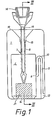
- Fig. 1 shows a preferred embodiment of the device. 2
- this device which is also referred to as a dispenser, has two layers, namely a first layer 1, which forms a chamber 2 for receiving an active substance block or the like by deep-drawing, and a second layer 3, which forms the rear side of the chamber 2 closes and is partially connected to the layer 1, parts of the layers 1 and 3 being parallel to one another with the exception of regions which are formed by the chamber 2 and channels or pipes to be described.
- the preferred embodiment of the device shown in FIG. 1 has layers 1 and 2 of equal area in plan view.
- layer 1 defines, in addition to chamber 2, a siphon tube 5 attached to the side and an upper inlet duct 6, which is vertical when the device is in use.
- a further opening 8 is provided on the side of the chamber 2 and enables a connection to the siphon tube 5.
- the siphon tube 5 is in the illustrated embodiment approximately from half the height of the chamber 2 extending vertically upwards and has approximately the height of the opening 7 or below the siphon section 10, to which an approximately vertically downwardly extending pipe section adjoins defines an outwardly facing opening 12.
- Layer 1 consists of a preferably transparent or translucent plastic material which can be shaped by a deep-drawing process in order to form the finished layer 1, which is provided with chambers, siphon pipe, etc. and which, after the deep-drawing process, coincides with or parallel to the material layer 3 - areas are firmly connected.
- the material layer 3 consists of a water-resistant material, for example water-resistant paper, plastic film, PVC, polyethylene, plastic-metal laminates or paper laminates. It is essential that the layer 3 does not dissolve when the device is used in the cistern of a toilet, and is at least largely resistant to chemicals.
- the layer 3 should have such surface properties that it can be provided with a print on the surface facing the layer 1 or preferably on its two surfaces in order to be able to provide prints, such as advertising texts, etc., on both surfaces.
- the lower surface, or a foot 14, of the chamber 2 is designed such that it protrudes at an angle of 90 ° from the lower edge 3a of the layer 3 or from the layer 3 runs obliquely downwards, as shown in FIG. 2.
- the foot 14a forms a pedestal, preferably at the same level as the edge 3a of the material layer 3, so that the entire device can preferably be kept standing upright on a shelf.
- the upper opening 7 of the chamber 2 opens into a vertical channel 6, which is provided for receiving a foot 16 of a fastening hook 18 and is used to prevent the entry of water into a cistern with increasing water level To allow water through the channel 6 and the opening 7 into the chamber 2, ie as soon as the water level in the cistern exceeds the upper edge labeled 19. This enables the entry of water into the chamber 2 and the action of water on an active substance block designated 21.
- the siphon tube 5 serving, as is known, to ensure a metered delivery of water dissolved with active ingredient.
- the foot 16 of the fastening hook is already inserted into the device when it is placed on the shelf.
- the foot 16 of the fastening hook 18 can be adjusted in height relative to the device, in order in this way to enable the upper edge 10 to be adjusted to the maximum water level in the cistern.
- the foot 16 is provided with lateral projections 15 which have a clear width which is selected to be slightly larger than the clear width of the channel 6, as a result of which the foot 16 is locked within the channel 6 after appropriate adjustment of the fastening hook 18 relative to the device. From Fig. 1 it can be seen that the chamber 2 is larger or higher than the active ingredient block 21. This ensures that a sufficient amount of water to dissolve the active ingredient block is introduced into the chamber 2.
- the foot 16 of the fastening hook 18 is in a separate from the chamber 2, one side, i.e. used from above open channel 22, which is thus not in communication with the chamber 2 and only fulfills the function of forming the receptacle for the foot 16 of the fastening hook 18.
- the chamber 2 containing the active substance block has an upwardly extending section 2a which is provided on its upper side with an inlet opening 7a; if the volume of the water to be fed into the chamber 2 is to be greater, a second, upwardly elongated chamber section 2b with an opening 7b can be provided, as indicated in FIG.
- a channel 22 for receiving the hook is preferably located centrally in the device between the two additional chamber sections 2a, 2b.
- the channel is located laterally next to the chamber section 2a and above the chamber 2, but it can in principle also be arranged next to the chamber 2 with a volume of any size relative to the active substance block 21.
- the two layers namely the first material layer 1 and the second layer 3, which forms the covering layer or sealing layer, are glued, welded or connected in some other way, namely in the. Areas in which layers 1 and 3 run parallel to one another and lie directly next to one another. There is therefore no fastening in areas within which the chamber 2, the chamber sections 2a, 2b or the channels or siphon tubes are formed.
- the invention thus provides a device for receiving an active substance block, which enables a metered dispensing of water dissolved with active substance when actuating a cistern, this device being used in the cistern as it is offered for sale on the shelf without any requirement additional packaging without the need to open the packaging and without the need to make the device with the fastening hook ready for operation.
- the device according to the invention can be used directly in a cistern, with the fastening hooks 18 only having to be adjusted relative to the device if necessary in order to ensure a coordination between the maximum water level in the cistern and the upper edge of the device for the purpose of water entering the device.
- the channel 6 is funnel-shaped in the direction of the upper edge.
- the foot 16 can be provided with a groove-like depression along its axis. This groove-shaped recess is provided for the introduction of water to the chamber 2 when the clear width and clear width of the channel 6 corresponds to the clear width and clear width of the foot 16 with the lateral detents or teeth 15, so that a safe introduction of water from the upper edge 19 forth into the chamber 2 is ensured via the groove-shaped depression running in the longitudinal direction of the foot 16; otherwise the water flow through the channel 6 would be at least severely impaired due to the cross section of the foot 16.
- the foot In order to allow an easy insertion of the foot 16 into the device, the foot is tapered at its underside, which enables the foot 16 to be used in the factory and at the same time prevents the foot 16 from being accidentally removed from the chamber 2 or the channel by the user 6 or 22 is pulled out.
- the operation of the device described is as follows. After inserting the device into the cistern of a toilet, the device is inserted into the cistern by the height-adjustable fastening hook in such a way that the upper edge 19 comes to lie slightly below the maximum water level of the cistern. After the cistern has been emptied or partially emptied, the water level in the cistern rises, the preferably vertical siphon tube section running downward from the siphon section 10 being gradually filled with water until the water level in the cistern exceeds the height of the siphon section. As a result, no water is introduced into the chamber 2 via the siphon section 10, so that the water level in the cistern continues to rise until it reaches its maximum level.
- the water level in the cistern exceeds a height which corresponds to the upper edge 19, the water enters the chamber 2 via the channels 6 and 22 and the opening 7, the chamber 2 filling up completely with water.
- the active ingredient block 21 is thereby dissolved. Any sludge arising due to the dissolution or dissolution of the active substance block 21 remains in the lower part of the chamber 2, i.e. in the area of the chamber 2 in which the active ingredient block 21 is located, thus in the embodiment shown below the opening 8 which is provided approximately in the center. If the cistern is actuated, the water level drops rapidly to a level which is below the lower edge 3a of the device .
- the first and second layers consist of a water-impermeable and at the same time water-resistant material, for example in the form of a solid plastic film, of which the film forming the second layer 3 is provided with advertising prints or the like.
- the second layer 3 is printed or printed before the two layers 1 and 3 are connected.
Description
Die Erfindung betrifft eine Vorrichtung entsprechend dem Oberbegriff des Patentanspruch 1.The invention relates to a device according to the preamble of
Eine Vorrichtung der eingangs genannten Art ist aus der US-A 4 455 692 bekannt. Diese Vorrichtung besteht aus zwer Schichten 21,"22 aus Kunststoffmaterial, von denen die eine Schicht 21 zur Festlegung von Kammern 14, 17 tiefgezogen oder durch andere Formgebung entsprechend ausgebildet ist. Beide Schichten 21 und 22 legen damit Kammern 14, 17 fest, die jeweils Abstand zur Kante des durch die beiden Schichten 21, 22 gebildeten Grundelements einhalten. Um eine solche Vorrichtung zum Verkauf anzubieten und in Regalen oder dergleichen aufzustellen, muß diese Vorrichtung in eine Verpackung eingesetzt werden und die Verpackung wird mit einem ihren Inhalt darstellenden Aufdruck versehen. Ohne Verpackung kann die bekannte Vorrichtung nicht in einem Regal oder dergleichen aufgestellt werden. Die Verpackung ist bei dieser Vorrichtung außerdem notwendig, um die erforderlichen Benutzungshinweise usw. in Form von gedruckten Texten aufzunehmen.A device of the type mentioned is known from US-A 4,455,692. This device consists of two
Aus dem DE-U 7 919 664 ist eine Vorrichtung bekannt, die aus einem kammerförmigen Behälter, einem Deckel und einem seitlich einsatzfähigen Saugheber besteht. Bei dieser Vorrichtung ist ein Befestigungshaken am Behälter angeformt. Obgleich sich diese Vorrichtung zum Einsatz in einen Spülkasten eignet, wird sie herkömmlicherweise mit einer Verpackung versehen und zusammen mit dieser Verpackung dem Käufer angeboten. Damit ist auch diese Vorrichtung mit dem Nachteil behaftet, eine zusätzliche Verpackung aufzuweisen, so daß zum Zwecke des Einsatzes dieser Vorrichtung die Verpackung aufgerissen, weggeworfen und die Vorrichtung selbst in den Spülkasten eingesetzt werden muß.From DE-U 7 919 664 a device is known which consists of a chamber-shaped container, a lid and a suction lifter which can be used laterally. In this device, a fastening hook is formed on the container. Although this device is suitable for use in a cistern, it is conventionally provided with a packaging and offered to the buyer together with this packaging. This device also has the disadvantage of having additional packaging, so that for the purpose of using this device the packaging has to be torn open, thrown away and the device itself has to be inserted into the cistern.
Der Erfindung liegt die Aufgabe zugrunde, eine Vorrichtung der eingangs genannten Art derart auszubilden, daß sie jegliche zusätzliche Verpackung entbehrlich macht.The invention has for its object to design a device of the type mentioned in such a way that it makes any additional packaging unnecessary.
Diese Aufgabe wird durch die Merkmale im kennzeichnenden Teil des Patentanspruchs 1 gelöst. Weitere Merkmale ergeben sich aus den Unteransprüchen.This object is achieved by the features in the characterizing part of
Die erfindungsgemäße Vorrichtung beinhaltet den Vorteil, daß der blockförmige oder tablettenförmige Wirkstoff berührungslos in den Spülkasten eines WC verbringbar ist und daß insbesondere die Verwendung einer zum Zwecke des Gebrauchs der Vorrichtung entfernbare Verpackung entfällt.The device according to the invention has the advantage that the block-shaped or tablet-shaped active ingredient can be brought into the cistern of a toilet without contact and that in particular the use of a packaging which can be removed for the purpose of using the device is dispensed with.
Die erfindungsgemäß nicht notwendige Verpackung führt dazu, daß die Kosten für die Herstellung der Verpackung entfallen und somit sich eine wesentliche Einsparung bei der Herstellung einer Vorrichtung ergibt.The packaging which is not necessary according to the invention means that the costs for the production of the packaging are eliminated and thus there is a substantial saving in the production of a device.
Besonders vorteilhaft ist, daß die erfindungsgemäße Vorrichtung in einem Regal aufstellbar ist und in dieser Form direkt in den Spülkasten eines WC eingebracht werden kann, wobei nach einer bevorzugten Ausführungsform der Befestigungshaken höhenverstellbar in die Vorrichtung eingesetzt ist.It is particularly advantageous that the device according to the invention can be set up on a shelf and in this form can be introduced directly into the cistern of a toilet, the height of the fastening hook being inserted into the device according to a preferred embodiment.
Die Vorrichtung ist mit einer Eintrittsöffnung und einer Austrittsöffnung versehen, so daß während des Ablaufes eines Spülvorganges das in der Kammer befindliche, mit dem Wirkstoffmaterial gelöste Wasser vorzugsweise in dosierter Form mit Hilfe eines Siphonrohres, austreten kann und nach dem Spülvorgang über die Einfüllöffnung frisches Wasser in die Kammer während des Anstiegs des Wasserniveaus im Spülkasten zum weiteren Auflösen des Wirkstoffmaterials eintreten kann.The device is provided with an inlet opening and an outlet opening, so that during the course of a rinsing process the water in the chamber, dissolved with the active ingredient material, can escape, preferably in a metered form, with the aid of a siphon tube and fresh water after the rinsing process via the filler opening the chamber can enter the cistern to further dissolve the drug material as the water level rises.
Besonders vorteilhaft ist die Verwendung eines Materials für die zweite Schicht, welches neben wasserbeständigen Eigenschaften das Vorsehen von Aufdrucken auf einer oder auf beiden Flächen dieses Materials ermöglicht. Damit können die notwendigen Werbeaufdrucke und dergleichen auf der Vorder- oder Rückseite der zweiten Schicht vorgesehen werden. Es entfallen zusätzliche Materialschichten oder verpackungen als Träger für Werbeaufdrucke usw. Die erste Materialschicht besteht vorzugsweise aus einem durchsichtigen oder opaken Material einerseits zur Feststellung, ob der Wirkstoffblock aufgebraucht ist und andererseits zur Vermittlung der Werbeaufdrucke auf der zweiten Schicht.It is particularly advantageous to use a material for the second layer which, in addition to water-resistant properties, enables prints to be provided on one or both surfaces of this material. The necessary advertising prints and the like can thus be provided on the front or back of the second layer. There are no additional layers of material or packaging as carriers for advertising prints, etc. The first material layer preferably consists of a transparent or opaque material on the one hand to determine whether the active substance block has been used up and on the other hand to convey the advertising prints on the second layer.
Im folgenden werden bevorzugte Ausführungsformen der Vorrichtung anhand der Zeichnung beschrieben. Es zeigen:
- Fig. 1 eine Draufsicht auf eine Vorrichtung,
- Fig. 2 eine Schnittansicht entlang der Linie II-II in Fig. 1, und
- Fig. 3 eine gegenüber Fig. 1 abgewandelte Ausführungsform.
- 1 is a plan view of a device,
- Fig. 2 is a sectional view taken along the line II-II in Fig. 1, and
- Fig. 3 shows a modified embodiment compared to FIG. 1.
Fig. 1 zeigt eine bevorzugte Ausführungsform der Vorrichtung. Diese Vorrichtung, die auch als Dispenser bezeichnet wird, weist nach Fig. 2 zwei Schichten auf, nämlich eine erste Schicht 1, die durch Tiefziehen eine Kammer 2 zur Aufnahme eines Wirkstoffblockes oder dergleichen bildet, und eine zweite Schicht 3, die die Rückseite der Kammer 2 abschließt und teilweise mit der Schicht 1 in Verbindung steht, wobei Teile der Schichten 1 und 3 parallel zueinander liegen mit Ausnahme solcher Bereiche, die durch die Kammer 2 und noch zu beschreibende Kanäle bzw. Rohre gebildet sind.Fig. 1 shows a preferred embodiment of the device. 2, this device, which is also referred to as a dispenser, has two layers, namely a
Die in Fig. 1 gezeigte bevorzugte Ausführungsform der Vorrichtung weist in Draufsicht flächengleiche Schichten 1 und 2 auf. Die Schicht 1 definiert neben der Kammer 2 bei dieser Ausführungsform ein seitlich angesetztes Siphonrohr 5 und einen oberen, im Gebrauch der Vorrichtung vertikal liegenden Eintrittskanal 6. An der oberseite der Kammer 2 ist grundsätzlich eine mit 7 angedeutete Öffnung vorgesehen, die bei der Ausführungsform nach Fig. 1 in den Kanal 6 mündet. Seitlich der Kammer 2 ist eine weitere Öffnung 8 vorgesehen, die eine Verbindung zum Siphonrohr 5 ermöglicht. Das Siphonrohr 5 ist bei der dargestellten Ausführungsform etwa von der halben Höhe der Kammer 2 vertikal nach oben verlaufend und weist etwa in der Höhe der Öffnung 7 oder darunter den Siphon abschnitt 10 auf, an den sich ein etwa vertikal nach unten erstreckender Rohrabschnitt anschließt, der eine nach außen weisende Öffnung 12 definiert.The preferred embodiment of the device shown in FIG. 1 has
Die Schicht 1 besteht aus einem vorzugsweise durchsichtigen oder durchscheinenden Kunststoffmaterial, das durch einen Tiefziehvorgang formbar ist, um die fertige, mit Kammern, Siphonrohr etc. versehene Schicht 1 zu bilden, welche nach dem Tiefziehvorgang mit der Materialschicht 3 in den sich deckenden bzw: parallelen-ßereichen fest verbunden wird. Die Materialschicht 3 besteht aus einem wasserbeständigen Material, beispielsweise wasserbeständigem Papier, Kunststoffolie, PVC, Polyäthylen, Kunstoff-Metall-Läminaten oder aus Papierlaminaten. Wesentlich ist, daß sich die Schicht 3 beim Einsatz der Vorrichtung in den Spülkasten eines WC durch das Wasser nicht auflöst, auch gegen Chemikalien zumindest weitgehend beständig ist. Außerdem soll die Schicht 3 solche Oberflächeneigenschaften haben, daß sie mit einem Druck versehen werden kann und zwar auf der zur Schicht 1 gewandten Fläche oder vorzugsweise auf ihren beiden Flächen, um auf beiden Flächen Drucke, wie Werbetexte usw. vorsehen zu können.
Um die Vorrichtung in einem Regal oder dergleichen aufstellen zu können, ist die untere Fläche, bzw. ein Fuß 14, der Kammer 2 so ausgebildet, daß er unter einem Winkel von 90° an der unteren Kante 3a der Schicht 3 absteht oder von der Schicht 3 nach unten schräg verläuft, wie dies in Fig. 2 gezeigt ist. Im letzteren Falle bildet der Fuß 14a einen Standfuß auf vorzugsweise gleichem Niveau zur Kante 3a der Materialschicht 3, so daß die gesamte Vorrichtung vorzugsweise senkrecht stehend in einem Regal aufbewahrt werden kann.In order to be able to set up the device on a shelf or the like, the lower surface, or a
Bei der Ausführungsform nach Fig. 1 und 2 mündet die obere Öffnung 7 der Kammer 2 in einen vertikalen Kanal 6, der zur Aufnahme eines Fußes 16 eines Befestigungshakens 18 vorgesehen ist und dazu dient, während des Einsatzes in einem Spülkasten mit ansteigendem Wasserspiegel den Eintritt von Wasser über den Kanal 6 und die Öffnung 7 in die Kammer 2 zu ermöglichen, d.h. sobald das Wasserniveau im Spülkasten die mit 19 bezeichnete obere Kante übersteigt. Dadurch wird der Eintritt von Wasser in die Kammer 2 ermöglicht und die Einwirkung von Wasser auf einen mit 21 bezeichneten Wirkstoffblock. Beim Entleeren des Spülkastens tritt das mit Wirkstoff gelöste Wasser über das Siphonrohr 5 und die Offnung 12 in den Spülkasten aus, wird also in das WC mit abgesogen, wobei das Siphonrohr 5 bekannterweise dazu dient, eine dosierte Abgabe von mit Wirkstoff gelöstem Wasser sicherzustellen.In the embodiment according to FIGS. 1 and 2, the upper opening 7 of the
Um die erfindungsgemäße Vorrichtung ohne weitere Maßnahmen in einem Spülkasten verwenden zu können, ist der Fuß 16 des Befestigungshakens bereits bei im Regal aufgestellter Vorrichtung in diese eingesetzt.In order to be able to use the device according to the invention in a cistern without further measures, the
Nach einer bevorzugten Ausführungsform läßt sich der Fuß 16 des Befestigungshakens 18 höhenverstellbar gegenüber der Vorrichtung verschieben, um auf diese Weise eine Angleichung der oberen Kante 10 auf den maximalen Wasserstabd im Spülkasten zu ermöglichen. Nach einer Ausführungsform ist zur höhenverstellbaren Arretierung des Fußes 16 des Befestigungshakens 18 der Fuß 16 mit seitlichen Vorsprüngen 15 versehen, die eine lichte Weite haben, welche geringfügig größer als die lichte Weite des Kanals 6 gewählt ist, wodurch ein Arretieren des Fußes 16 innerhalb des Kanals 6 nach entsprechender Einstellung des Befestigungshakens 18 gegenüber der Vorrichtung gegeben ist. Aus Fig. 1 ist erkennbar, daß die Kammer 2 größer bzw. höher ist als der Wirkstoffblock 21. Hierdurch wird erreicht, daß in die Kammer 2 eine zur Anlösung des Wirkstoffblockes ausreichende Wassermenge eingeführt wird.According to a preferred embodiment, the
Bei der in Fig. 3 gezeigten abgewandelten Ausführungsform ist der Fuß 16 des Befestigungshakens 18 in einem zur Kammer 2 separaten, einseitig, d.h. von oben offenen Kanal 22 eingesetzt, der somit nicht in Verbindung mit der Kammer 2 steht und lediglich die Funktion erfüllt, die Aufnahme für den Fuß 16 des Befestigungshakens 18 zu bilden. Um eine vorbestimmte Menge an Wasser in die Vorrichtung einleiten zu können, weist die den Wirkstoffblock enthaltende Kammer 2 einen sich nach oben erstreckenden Abschnitt 2a auf, der an seiner oberen Seite mit einer Eintrittsöffnung 7a versehen ist; soll das Volumen des in die Kammer 2 zuzuführenden Wassers größer sein, kann, wie in Fig. 3 angedeutet, eine zweiter, nach oben verlängerter Kammerabschnitt 2b mit einer Öffnung 7b vorgesehen sein; in diesem Fall liegt ein Kanal 22 zur Aufnahme des Hakens vorzugsweise mittig in der Vorrichtung zwischen den beiden zusätzlichen Kammerabschnitten 2a, 2b. Im ersten Fall liegt der Kanal seitlich neben dem Kammerabschnitt 2a und oberhalb der Kammer 2, er kann jedoch auch grundsätzlich neben der Kammer 2 mit zum Wirkstoffblock 21 beliebig größerem Volumen angeordnet sein.In the modified embodiment shown in Fig. 3, the
Obgleich es in den Zeichnungen nicht weiter dargestellt ist, ist ersichtlich, daß die beiden Schichten, nämlich die erste Materialschicht 1 und die zweite, die Abdeckschicht oder Verschlußschicht bildende Schicht 3 miteinander verklebt,verschweißt oder auf andere Weise verbunden sind, und zwar in den. Bereichen, in denen die Schichten 1 und 3 parallel zueinander und direkt nebeneinander liegend verlaufen. Keine Befestigung liegt somit vor in solchen Bereichen, innerhalb welchen die Kammer 2, die Kammerabschnitte 2a, 2b oder die Kanäle bzw. Siphonrohre gebildet sind.Although it is not shown in the drawings, it can be seen that the two layers, namely the
Die Erfindung schafft somit eine Vorrichtugng zur Aufnahme eines Wirkstoffblockes, die eine dosierte Ausgabe von mit Wirkstoff gelöstem Wasser beim Betätigen eines Spülkastens ermöglicht, wobei diese Vorrichtung so, wie sie im Regal zum Kauf angeboten wird, in den Spülkasten eingesetzt wird, ohne eine Erfordernis an zusätzlicher Verpackung, ohne die Notwendigkeit, Verpackung zu öffnen und ohne die Notwendigkeit, die Vorrichtung mit dem Befestigungshaken betriebsfertig zu machen. Die erfindungsgemäße Vorrichtung ist direkt in einem Spülkasten einsatzfähig, wobei lediglich im Bedarfsfall der Befestigungshaken 18 gegenüber der Vorrichtung verstellt werden muß, um eine Abstimmung zwischen dem maximalen Wasserstand im Spülkasten und der oberen Kante der Vorrichtung zum Zwecke des Eintritts von Wasser in die Vorrichtung sicherzustellen.The invention thus provides a device for receiving an active substance block, which enables a metered dispensing of water dissolved with active substance when actuating a cistern, this device being used in the cistern as it is offered for sale on the shelf without any requirement additional packaging without the need to open the packaging and without the need to make the device with the fastening hook ready for operation. The device according to the invention can be used directly in a cistern, with the
Nach einer bevorzugten Ausführungsform ist der Kanal 6 in Richtung auf die obere Kante trichterförmig erweitert. Der Fuß 16 kann mit einer nutartigen Vertiefung entlang seiner Achse versehen sein. Diese nutförmige Vertiefung ist zur Wassereinleitung zur Kammer 2 vorgesehen, wenn die lichte Weite und lichte Breite des -Kanals 6 der lichten Weite und lichten Breite des Fußes 16 mit den seitlichen Arretierungen bzw. Zähnen 15 entspricht, so daß eine sichere Einleitung von Wasser von der oberen Kante 19 her in die Kammer 2 über die in Längsrichtung des Fußes 16 verlaufende nutförmige Vertiefung gewährleistet ist; anderenfalls wäre der Wasserdurchfluß durch den Kanal 6 aufgrund des Querschnitts des Fußes 16 zumindest stark beeinträchtigt.According to a preferred embodiment, the
Um ein leichtes Einschieben des Fußes 16 in die Vorrichtung zu ermöglichen, ist der Fuß an seiner Unterseite pfeilförmig auslaufend ausgebildet, was den Ensatz des Fußes 16 fabrikseitig ermöglicht und gleichzeitig verhindert, daß der Fuß 16 vom Anwender versehentlich aus der Kammer 2 bzw. dem Kanal 6 oder 22 herausgezogen wird.In order to allow an easy insertion of the
Die Funktionsweise der beschriebenen Vorrichtung ist wie folgt. Nach dem Einsetzen der Vorrichtung in den Spülkasten eines WC wird die Vorrichtung durch den höhenverstellbaren Befestigungshaken derart in den Spülkasten eingesetzt, daß die obere Kante 19 geringfügig unterhalb des maximalen Wasserstandes des Spülkastens zu liegen kommt. Nach einem Entleeren oder teilweisen Entleeren des Spülkastens steigt der Wasserstand im Spülkasten an, wobei der vom Siphonabschnitt 10 nach unten verlaufende, vorzugsweise vertikale Siphonrohrabschnitt allmählich mit Wasser aufgefüllt wird, bis der Wasserstand im Spülkasten die Höhe des Siphonabschnittes überschreitet. Über den Siphonabschnitt 10 wird dadurch kein Wasser in die Kammer 2 eingeleitet, so daß der Wasserstand im Spülkasten weiter ansteigt, bis er sein maximales Niveau erreicht. Wenn der Wasserstand im Spülkasten eine Höhe überschreitet, die der oberen Kante 19 entspricht, tritt das Wasser über den Kanal 6 bzw. 22 und die Öffnung 7 in die Kammer 2 ein, wobei sich die Kammer 2 vollständig mit Wasser auffüllt. Dadurch wird der Wirkstoffblock 21 angelöst. Etwa entstehender Schlamm aufgrund der Auflösung oder Anlösung des Wirkstoffblockes 21 verbleibt in dem unteren Teil der Kammer 2, d.h. in dem Bereich der Kammer 2, in welchem der Wirkstoffblock 21 liegt, somit bei der dargestellten Ausführungsform unterhalb der etwa mittig vorgesehen Öffnung 8. Wird der Spülkasten betätigt, sinkt der Wasserstand rasch ab auf ein Niveau, das unterhalb der unteren Kante 3a der Vorrichtung liegt. Während der Entleerung oder teilweisen Entleerung des Spülkastens wird aus der Kammer 2 Flüssigkeit, die mit dem Wirkstoff gelöst ist, über das Siphonrohr 5 abgezogen, wobei sich die Kammer 2 bis zu einem Niveau von der Öffnung 7 her entleert, das durch die Öffnung 8 begrenzt ist. Auf diese Weise erfolgt eine Dosierung, wobei die dosierte Lösungsmenge praktisch dem Kammervolumen entspricht, das durch die beiden Öffnungen 7, 8 festgelegt ist. Die im Kanal 6 befindliche Wassermenge kann hierbei vernachlässigt werden. Die Ausbildung der Öffnung 8 zum Siphonrohr 5 oberhalb des Wirkstoffblockes 21 hat gleichzeitig zum Vorteil, daß am Boden der Kammer 2 befindlicher Lösungsschlamm des Wirkstoffblockes 21, somit Wirkstoff in konzentrierter Form, nicht oder nur in geringfügigster Menge, aus der Kammer 2 über das Siphonrohr 5 ausgegeben wird und auch das Siphonrohr 5 nicht verstopfen laßt.The operation of the device described is as follows. After inserting the device into the cistern of a toilet, the device is inserted into the cistern by the height-adjustable fastening hook in such a way that the
Bei der erfindungsgemäßen Vorrichtung bestehen die erste und zweite Schicht aus einem wasserundurchlässigen und gleichzeitig wasserbeständigen Material, beispielsweise in Form einer festen Kunststoffolie, von denen die die zweite Schicht 3 bildende Folie mit Werbedrucken oder dergleichen versehen ist. Das Aufdrucken oder Bedrucken der zweiten Schicht 3 erfolgt vor der Verbindung der beiden Schichten 1 und 3.In the device according to the invention, the first and second layers consist of a water-impermeable and at the same time water-resistant material, for example in the form of a solid plastic film, of which the film forming the
Claims (6)
Applications Claiming Priority (2)
| Application Number | Priority Date | Filing Date | Title |
|---|---|---|---|
| DE3542944 | 1985-12-04 | ||
| DE19853542944 DE3542944A1 (en) | 1985-12-04 | 1985-12-04 | DEVICE FOR ADDING DISINFECTANT OR THE LIKE IN THE WATER WATER IN A WC |
Publications (3)
| Publication Number | Publication Date |
|---|---|
| EP0224767A2 EP0224767A2 (en) | 1987-06-10 |
| EP0224767A3 EP0224767A3 (en) | 1987-08-19 |
| EP0224767B1 true EP0224767B1 (en) | 1990-02-07 |
Family
ID=6287659
Family Applications (1)
| Application Number | Title | Priority Date | Filing Date |
|---|---|---|---|
| EP86115707A Expired - Lifetime EP0224767B1 (en) | 1985-12-04 | 1986-11-12 | Device for adding a disinfectant or the like to the flushing water of a toilet |
Country Status (8)
| Country | Link |
|---|---|
| US (1) | US4707866A (en) |
| EP (1) | EP0224767B1 (en) |
| AU (1) | AU589705B2 (en) |
| CA (1) | CA1275352C (en) |
| DE (2) | DE3542944A1 (en) |
| ES (1) | ES2012758B3 (en) |
| GR (1) | GR3000364T3 (en) |
| PT (1) | PT83854B (en) |
Families Citing this family (13)
| Publication number | Priority date | Publication date | Assignee | Title |
|---|---|---|---|---|
| AU594572B2 (en) * | 1988-05-05 | 1990-03-08 | R & C Assets Pty Limited | Dispenser |
| US5073993A (en) * | 1990-07-12 | 1991-12-24 | Dewaal Peter K | Toilet bowl dispenser hanger |
| US6055679A (en) * | 1995-03-03 | 2000-05-02 | S. C. Johnson & Son, Inc. | Passive lavatory cleanser dispensing system |
| WO2005098153A1 (en) * | 2004-04-06 | 2005-10-20 | Mc Nabb, John, Russell | Cistern additive metering device |
| GB0522660D0 (en) * | 2005-11-07 | 2005-12-14 | Reckitt Benckiser Nv | Assembly and device |
| US20090170743A1 (en) | 2006-01-21 | 2009-07-02 | Reckitt Benckiser N.V. | Article |
| CA2633111A1 (en) * | 2006-01-21 | 2007-07-26 | Reckitt Benckiser N.V. | Dosage element and chamber |
| GB0621569D0 (en) * | 2006-10-30 | 2006-12-06 | Reckitt Benckiser Nv | Mounting device |
| GB0621572D0 (en) | 2006-10-30 | 2006-12-06 | Reckitt Benckiser Nv | Multi-dosing detergent delivery device |
| GB0710229D0 (en) * | 2007-05-30 | 2007-07-11 | Reckitt Benckiser Nv | Detergent dosing device |
| US10465366B2 (en) | 2014-05-27 | 2019-11-05 | As America, Inc. | Sanitaryware cleaning system |
| CR20160601A (en) | 2014-05-27 | 2017-07-19 | As Ip Holdco Llc | SANITARY CLEANING SYSTEM |
| CA3049027A1 (en) | 2017-01-25 | 2018-08-02 | As America, Inc. | Sanitaryware cleaning system |
Family Cites Families (19)
| Publication number | Priority date | Publication date | Assignee | Title |
|---|---|---|---|---|
| GB1219200A (en) * | 1968-05-29 | 1971-01-13 | Reckitt & Colmann Prod Ltd | Improvements in or relating to dispensing containers for use in flushing cisterns |
| FR2058493A5 (en) * | 1969-09-10 | 1971-05-28 | Soplaril Sa | |
| DE2155069A1 (en) * | 1971-11-05 | 1973-05-10 | Gundermann Unionpack | PACKAGING CONTAINERS FOR LIQUID AND PASTOESE SUBSTANCES |
| US3914805A (en) * | 1974-04-08 | 1975-10-28 | John E Dolan | Automatic room deodorizing device |
| US3953902A (en) * | 1975-01-17 | 1976-05-04 | Colgate-Palmolive Company | Water closet additive means |
| US4209863A (en) * | 1978-11-07 | 1980-07-01 | International Flavors & Fragrances Inc. | Process for aromatizing and/or deodorizing the environment surrounding the flush tank of a toilet |
| US4247070A (en) * | 1979-07-23 | 1981-01-27 | The Procter & Gamble Company | Tilt compensating hanger for toilet tank dispensing apparatus |
| US4436269A (en) * | 1980-11-28 | 1984-03-13 | The Procter & Gamble Company | Dispenser suspension means employing planar spring-loaded detent |
| US4462121A (en) * | 1982-03-19 | 1984-07-31 | The Procter & Gamble Company | Passageway resistant to capillary transport |
| FR2529598A1 (en) * | 1982-07-05 | 1984-01-06 | Lesieur Cotelle | DEVICE FOR DISPENSING A PRODUCT IN A RESERVOIR OF A WC HUNTING |
| FR2532347B1 (en) * | 1982-08-26 | 1987-02-20 | Oreal | DEVICE FOR THE DISPENSING OF WATER-SOLUBLE PRODUCTS IN A WATER FLUSH |
| NZ205595A (en) * | 1982-09-17 | 1987-06-30 | Reckitt & Colmann Prod Ltd | Dispensing device for suspension in toilet cistern |
| AU2309284A (en) * | 1983-01-06 | 1984-07-12 | American Home Products Corporation | Toilet bowl cleaning and disinfecting device |
| US4453278A (en) * | 1983-01-06 | 1984-06-12 | Knomark, Inc. | Chemical dispenser |
| US4485500A (en) * | 1983-01-06 | 1984-12-04 | Knomark, Inc. | Gas binding resistant chemical dispenser |
| US4455692A (en) * | 1983-05-09 | 1984-06-26 | The Drackett Company | Chemical dispenser safety hanger |
| FR2555144B1 (en) * | 1983-11-23 | 1986-04-18 | Rougemont Manufacture | COIL LINK ROLL, PACKAGED ON A DISPLAY, AND PROCESS FOR OBTAINING IT |
| FR2564502B1 (en) * | 1984-05-16 | 1986-10-24 | Oreal | DEVICE FOR THE DISPENSING OF WATER-SOLUBLE PRODUCTS IN A WATER FLUSH |
| US4581777A (en) * | 1985-03-29 | 1986-04-15 | The Drackett Company | Sealable dispenser and hanger |
-
1985
- 1985-12-04 DE DE19853542944 patent/DE3542944A1/en not_active Withdrawn
-
1986
- 1986-11-06 CA CA000522380A patent/CA1275352C/en not_active Expired - Lifetime
- 1986-11-07 AU AU64941/86A patent/AU589705B2/en not_active Ceased
- 1986-11-12 DE DE8686115707T patent/DE3668931D1/en not_active Expired - Lifetime
- 1986-11-12 EP EP86115707A patent/EP0224767B1/en not_active Expired - Lifetime
- 1986-11-12 ES ES86115707T patent/ES2012758B3/en not_active Expired - Lifetime
- 1986-12-02 PT PT83854A patent/PT83854B/en not_active IP Right Cessation
- 1986-12-03 US US06/937,256 patent/US4707866A/en not_active Expired - Fee Related
-
1990
- 1990-03-01 GR GR90400110T patent/GR3000364T3/en unknown
Also Published As
| Publication number | Publication date |
|---|---|
| PT83854A (en) | 1987-01-01 |
| EP0224767A2 (en) | 1987-06-10 |
| EP0224767A3 (en) | 1987-08-19 |
| ES2012758B3 (en) | 1990-04-16 |
| AU589705B2 (en) | 1989-10-19 |
| GR3000364T3 (en) | 1991-06-07 |
| PT83854B (en) | 1993-02-26 |
| AU6494186A (en) | 1987-06-11 |
| DE3542944A1 (en) | 1987-06-11 |
| US4707866A (en) | 1987-11-24 |
| CA1275352C (en) | 1990-10-23 |
| DE3668931D1 (en) | 1990-03-15 |
Similar Documents
| Publication | Publication Date | Title |
|---|---|---|
| EP0224767B1 (en) | Device for adding a disinfectant or the like to the flushing water of a toilet | |
| DE19912217C2 (en) | Device for dispensing active substances in the flushing water, especially in toilet bowls | |
| DE60128401T2 (en) | UNIT FOR PREPARING BEVERAGES FROM REFINABLE PRODUCTS | |
| WO2006136215A2 (en) | Flushing water guiding arrangement for a toilet bowl | |
| DE1961893A1 (en) | Bacterial barrier | |
| DE3304027A1 (en) | PASSIVE DELIVERY DEVICE | |
| DE19901457B4 (en) | Device for dispensing active substances into the flushing water of a toilet bowl or the like | |
| EP1458939B1 (en) | Device for feeding a liquid active ingredient into flushing water | |
| DE1815734A1 (en) | Device for storing and dispensing chemicals in a periodically emptied water container or the like. | |
| DE2037625B2 (en) | Deodorizing device | |
| EP1659227A1 (en) | Pressure flushing device | |
| DE19851754C2 (en) | Dosing device for dispensing a rinse water additive to a rinse water distributor | |
| DE102017127425B4 (en) | Drinking straw for the simplified production of a mixed drink | |
| EP0126966B1 (en) | Automatic dispenser for a water tank | |
| AT395450B (en) | DEVICE FOR DELIVERING A WATER-SOLUBLE AGENT INTO THE RINSING WATER | |
| EP1362538B1 (en) | Sink | |
| DE3728126A1 (en) | Metering device | |
| EP0204853A1 (en) | Device for the delivery of disinfectants and/or other agents to the flushing water of a toilet | |
| DE202008018400U1 (en) | System and capsule for preparing a drink | |
| DE8319782U1 (en) | DRINKING Trough FOR BIRD CAGE | |
| DE2742657C2 (en) | ||
| EP4290022A1 (en) | Pouring device, automatic deposit machine device with such a pouring device and method for the operation thereof | |
| EP0114569A1 (en) | Method for the supply of a device for dispensing measured quantities of a liquid soap, and device for carrying out the method | |
| DE102012209297B4 (en) | Water container of a sterilization device | |
| AT280901B (en) | Siphon valve for a liquid container |
Legal Events
| Date | Code | Title | Description |
|---|---|---|---|
| PUAI | Public reference made under article 153(3) epc to a published international application that has entered the european phase |
Free format text: ORIGINAL CODE: 0009012 |
|
| AK | Designated contracting states |
Kind code of ref document: A2 Designated state(s): AT BE CH DE ES FR GB GR IT LI NL SE |
|
| PUAL | Search report despatched |
Free format text: ORIGINAL CODE: 0009013 |
|
| AK | Designated contracting states |
Kind code of ref document: A3 Designated state(s): AT BE CH DE ES FR GB GR IT LI NL SE |
|
| 17P | Request for examination filed |
Effective date: 19871028 |
|
| 17Q | First examination report despatched |
Effective date: 19880802 |
|
| GRAA | (expected) grant |
Free format text: ORIGINAL CODE: 0009210 |
|
| AK | Designated contracting states |
Kind code of ref document: B1 Designated state(s): BE DE ES FR GB GR IT NL |
|
| ITF | It: translation for a ep patent filed |
Owner name: STUDIO FERRARIO |
|
| ET | Fr: translation filed | ||
| REF | Corresponds to: |
Ref document number: 3668931 Country of ref document: DE Date of ref document: 19900315 |
|
| GBT | Gb: translation of ep patent filed (gb section 77(6)(a)/1977) | ||
| REG | Reference to a national code |
Ref country code: GR Ref legal event code: FG4A Free format text: 3000364 |
|
| PLBE | No opposition filed within time limit |
Free format text: ORIGINAL CODE: 0009261 |
|
| STAA | Information on the status of an ep patent application or granted ep patent |
Free format text: STATUS: NO OPPOSITION FILED WITHIN TIME LIMIT |
|
| 26N | No opposition filed | ||
| PGFP | Annual fee paid to national office [announced via postgrant information from national office to epo] |
Ref country code: BE Payment date: 19910919 Year of fee payment: 6 |
|
| PGFP | Annual fee paid to national office [announced via postgrant information from national office to epo] |
Ref country code: GB Payment date: 19920814 Year of fee payment: 7 |
|
| PGFP | Annual fee paid to national office [announced via postgrant information from national office to epo] |
Ref country code: GR Payment date: 19920910 Year of fee payment: 7 |
|
| PGFP | Annual fee paid to national office [announced via postgrant information from national office to epo] |
Ref country code: FR Payment date: 19921123 Year of fee payment: 7 |
|
| PGFP | Annual fee paid to national office [announced via postgrant information from national office to epo] |
Ref country code: DE Payment date: 19921125 Year of fee payment: 7 |
|
| PG25 | Lapsed in a contracting state [announced via postgrant information from national office to epo] |
Ref country code: BE Effective date: 19921130 |
|
| PGFP | Annual fee paid to national office [announced via postgrant information from national office to epo] |
Ref country code: NL Payment date: 19921130 Year of fee payment: 7 Ref country code: ES Payment date: 19921130 Year of fee payment: 7 |
|
| BERE | Be: lapsed |
Owner name: GLOBOL-WERK G.M.B.H. Effective date: 19921130 |
|
| PG25 | Lapsed in a contracting state [announced via postgrant information from national office to epo] |
Ref country code: GB Effective date: 19931112 |
|
| PG25 | Lapsed in a contracting state [announced via postgrant information from national office to epo] |
Ref country code: ES Free format text: LAPSE BECAUSE OF NON-PAYMENT OF DUE FEES Effective date: 19931113 |
|
| PG25 | Lapsed in a contracting state [announced via postgrant information from national office to epo] |
Ref country code: GR Free format text: THE PATENT HAS BEEN ANNULLED BY A DECISION OF A NATIONAL AUTHORITY Effective date: 19940531 |
|
| PG25 | Lapsed in a contracting state [announced via postgrant information from national office to epo] |
Ref country code: NL Effective date: 19940601 |
|
| GBPC | Gb: european patent ceased through non-payment of renewal fee |
Effective date: 19931112 |
|
| NLV4 | Nl: lapsed or anulled due to non-payment of the annual fee | ||
| PG25 | Lapsed in a contracting state [announced via postgrant information from national office to epo] |
Ref country code: FR Effective date: 19940729 |
|
| PG25 | Lapsed in a contracting state [announced via postgrant information from national office to epo] |
Ref country code: DE Effective date: 19940802 |
|
| REG | Reference to a national code |
Ref country code: FR Ref legal event code: ST |
|
| REG | Reference to a national code |
Ref country code: GR Ref legal event code: MM2A Free format text: 3000364 |
|
| REG | Reference to a national code |
Ref country code: ES Ref legal event code: FD2A Effective date: 19941214 |
|
| PG25 | Lapsed in a contracting state [announced via postgrant information from national office to epo] |
Ref country code: IT Free format text: LAPSE BECAUSE OF NON-PAYMENT OF DUE FEES Effective date: 20051112 |