EP0223898B1 - Hydraulic lash adjusting device - Google Patents
Hydraulic lash adjusting device Download PDFInfo
- Publication number
- EP0223898B1 EP0223898B1 EP86102711A EP86102711A EP0223898B1 EP 0223898 B1 EP0223898 B1 EP 0223898B1 EP 86102711 A EP86102711 A EP 86102711A EP 86102711 A EP86102711 A EP 86102711A EP 0223898 B1 EP0223898 B1 EP 0223898B1
- Authority
- EP
- European Patent Office
- Prior art keywords
- spherical
- adjusting piston
- sliding shoe
- valve
- valve stem
- Prior art date
- Legal status (The legal status is an assumption and is not a legal conclusion. Google has not performed a legal analysis and makes no representation as to the accuracy of the status listed.)
- Expired
Links
Images

Classifications
-
- F—MECHANICAL ENGINEERING; LIGHTING; HEATING; WEAPONS; BLASTING
- F01—MACHINES OR ENGINES IN GENERAL; ENGINE PLANTS IN GENERAL; STEAM ENGINES
- F01L—CYCLICALLY OPERATING VALVES FOR MACHINES OR ENGINES
- F01L1/00—Valve-gear or valve arrangements, e.g. lift-valve gear
- F01L1/46—Component parts, details, or accessories, not provided for in preceding subgroups
-
- F—MECHANICAL ENGINEERING; LIGHTING; HEATING; WEAPONS; BLASTING
- F01—MACHINES OR ENGINES IN GENERAL; ENGINE PLANTS IN GENERAL; STEAM ENGINES
- F01L—CYCLICALLY OPERATING VALVES FOR MACHINES OR ENGINES
- F01L1/00—Valve-gear or valve arrangements, e.g. lift-valve gear
- F01L1/20—Adjusting or compensating clearance
- F01L1/22—Adjusting or compensating clearance automatically, e.g. mechanically
- F01L1/24—Adjusting or compensating clearance automatically, e.g. mechanically by fluid means, e.g. hydraulically
- F01L1/2411—Adjusting or compensating clearance automatically, e.g. mechanically by fluid means, e.g. hydraulically by means of a hydraulic adjusting device located between the valve stem and rocker arm
-
- F—MECHANICAL ENGINEERING; LIGHTING; HEATING; WEAPONS; BLASTING
- F01—MACHINES OR ENGINES IN GENERAL; ENGINE PLANTS IN GENERAL; STEAM ENGINES
- F01L—CYCLICALLY OPERATING VALVES FOR MACHINES OR ENGINES
- F01L1/00—Valve-gear or valve arrangements, e.g. lift-valve gear
- F01L1/12—Transmitting gear between valve drive and valve
- F01L1/18—Rocking arms or levers
- F01L2001/187—Clips, e.g. for retaining rocker arm on pivot
Definitions
- the invention relates to a hydraulic lash adjuster, in which a hydraulic compensation element is housed in a bore of a rocker arm or similar actuating element extending in the extension of the shaft of an engine valve, the longitudinally displaceable adjusting piston of which ends in a spherical projection towards the valve stem, between which and the flat end face of the valve stem Sliding shoe is arranged, which on the one hand has a spherical cap in which the spherical projection of the adjusting piston engages, and which on the other hand is supported with a flat surface on the end face of the valve stem.
- sliding shoes serve to create contact surfaces between the adjusting piston on the one hand and the valve stem on the other hand, by means of which wear is reduced and the lubrication conditions are improved.
- a sliding block is simply inserted between the spherical projection of the adjusting piston and the end face of the valve stem, where it is held in place during operation by the meshing of the spherical projection and the spherical cap.
- such a slide shoe has already been provided with a captive lock by allowing it to engage with a flanged edge in a circumferential groove in the valve stem. As a result, it is securely attached to the end of the valve stem when the rocker arms are removed and cannot be lost.
- the disadvantage here is that the engine manufacturer has to keep different valves in stock if he also produces valve controls with mechanical valve clearance adjustment in addition to valve controls with hydraulic lash adjusters (DE-OS 33 04 398).
- Brackets for such sliding shoes have also already been made, which are to be regarded as a kind of reversal of the previously described embodiment, in which the sliding shoe engages behind a reduction in diameter of the spherical projection on the adjusting piston with a flange.
- the invention has for its object to provide a secure mounting of the slide shoe on the hydraulic compensating element, without the need for an extension of the adjusting piston, and without changes to the valve stem being required.
- a cage part extends from a point lying behind the ball projection, which extends in the direction of the valve stem and ends there in radially inwardly directed holding zones which cover the outer lateral surface of the slide shoe or projections of this lateral surface in such a way reach behind that the sliding shoe is held captive against the adjusting piston with free angular mobility.
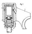
- a hydraulic compensating element 2 is mounted in the rocker arm 1 in a known manner, the adjusting piston 3 of which ends in a ball projection 5 at its end facing the valve stem 4.
- the sliding block 7 is arranged, in whose spherical cap 8 the spherical projection 5 of the adjusting piston 3 engages, and the flat end face 9 of which cooperates with the end face 6 of the valve stem 4.
- the outer surface of the sliding shoe 7 has a radially projecting collar 10 at its end facing the adjusting piston 3.
- a cage part 11 is molded into its circumferential groove 12 at its upper end for attachment to the adjusting piston 3.
- the cage part 11 is drawn in to the holding zones 13, which lie on an inner diameter which is smaller than the diameter of the collar 10.
- the distance of the holding zones 13 from the collar 10 in the axial direction is chosen so that the slide shoe 7 can pivot within the angular movements occurring during operation without hitting the holding zones 13. In this way, a secure mounting of the slide shoe 7 is ensured without its free adjustability being hindered by any adjacent components.
- the variant of the subject of the application shown in FIG. 2 differs from that of FIG. 1 only in that the slide shoe 14 provided here has an outer circumferential surface 15 which is formed as part of a spherical surface, the center of which coincides with the center of the spherical projection 5.
- the holding zones 13 of the cage part 11 end below the transverse plane 16 passing through the center of the spherical projection, as a result of which secure holding of the sliding block 14 and its free angular mobility is ensured.
Description
Die Erfindung betrifft eine hydraulische Spielausgleichsvorrichtung, bei der in einer in Verlängerung des Schaftes eines Motorventils verlaufenden Bohrung eines Kipphebels oder ähnlichen Betätigungsorganes ein hydraulisches Ausgleichselement untergebracht ist, dessen längsverschiebbarer Einstellkolben zum Ventilschaft hin in einem Kugelvorsprung endet, zwischen dem und der planen Stirnfläche des Ventilschaftes ein Gleitschuh angeordnet ist, der einerseits eine Kugelkalotte aufweist, in die der Kugelvorsprung des Einstellkolbens eingreift, und der andererseits sich mit einer Planfläche an der Stimfläche des Ventilschaftes abstützt.The invention relates to a hydraulic lash adjuster, in which a hydraulic compensation element is housed in a bore of a rocker arm or similar actuating element extending in the extension of the shaft of an engine valve, the longitudinally displaceable adjusting piston of which ends in a spherical projection towards the valve stem, between which and the flat end face of the valve stem Sliding shoe is arranged, which on the one hand has a spherical cap in which the spherical projection of the adjusting piston engages, and which on the other hand is supported with a flat surface on the end face of the valve stem.
Die Anordnung derartiger Gleitschuhe ist bekannt. Sie dienen dazu, zwischen dem Einstellkolben einerseits und dem Ventilschaft andererseits Berührungsflächen zu schaffen, durch welche der Verschleiß vermindert und die Schmierverhältnisse verbessert werden. Bei einer bekannten Ausführung ist ein solcher Gleitschuh einfach zwischen den Kugelvorsprung des Einstellkolbens und die Stirnfläche des Ventilschaftes eingelegt, wo er während des Betriebes durch das Ineinandergreifen von Kugelvorsprung und Kalotte an Ort und Stelle gehalten wird. Bei der Demontage der Kipphebei besteht jedoch die Gefahr, daß der Gleitschuh in den Motorblock fällt, von wo er nur sehr schwierig wieder entfernt werden kann (DE-OS 31 18 466).The arrangement of such sliding shoes is known. They serve to create contact surfaces between the adjusting piston on the one hand and the valve stem on the other hand, by means of which wear is reduced and the lubrication conditions are improved. In a known embodiment, such a sliding block is simply inserted between the spherical projection of the adjusting piston and the end face of the valve stem, where it is held in place during operation by the meshing of the spherical projection and the spherical cap. When dismantling the tipping hoist, however, there is a risk that the slide shoe will fall into the engine block, from where it can be removed only with great difficulty (DE-OS 31 18 466).
Bei einer anderen Ausführung hat man einen solchen Gleitschuh bereits mit einer Verliersicherung versehen, indem man ihn mit einem umgebördelten Rand in eine umlaufende Nut des Ventilschaftes eingreifen ließ. Dadurch ist er auch bei der Demontage der Kipphebel sicher am Ventilschaftende befestigt und kann nicht verlorengehen. Nachteilig ist hierbei, daß der Motorenhersteller unterschiedliche Ventile auf Lager halten muß, wenn er neben Ventilsteuerungen mit hydraulischen Spielausgleichsvorrichtungen auch Ventilsteuerungen mit mechanischer Ventilspieleinstellung herstellt (DE-OS 33 04 398).In another embodiment, such a slide shoe has already been provided with a captive lock by allowing it to engage with a flanged edge in a circumferential groove in the valve stem. As a result, it is securely attached to the end of the valve stem when the rocker arms are removed and cannot be lost. The disadvantage here is that the engine manufacturer has to keep different valves in stock if he also produces valve controls with mechanical valve clearance adjustment in addition to valve controls with hydraulic lash adjusters (DE-OS 33 04 398).
Es wurden auch schon Halterungen für derartige Gleitschuhe ausgeführt, die als eine Art Umkehrung der vorher beschriebenen Ausführung anzusehen sind, bei der nämlich der Gleitschuh mit einer Einbördelung hinter eine Durchmesserverringerung des Kugelvorsprungs am Einstellkolben greift. Diese bedingt jedoch, daß der Kugelvorsprung am Einstellkolben deutlich verlängert werden muß, um den axial erforderlichen Raum für diese Durchmesserverringerung zu schaffen. Diese zusätzlich erforderliche Einbaulänge steht jedoch in vielen Fällen nicht zur Verfügung.Brackets for such sliding shoes have also already been made, which are to be regarded as a kind of reversal of the previously described embodiment, in which the sliding shoe engages behind a reduction in diameter of the spherical projection on the adjusting piston with a flange. However, this means that the ball projection on the adjusting piston must be extended significantly in order to create the axially required space for this diameter reduction. In many cases, however, this additional installation length is not available.
Der Erfindung liegt die Aufgabe zugrunde, eine sichere Halterung des Gleitschuhs am hydraulischen Ausgleichselement zu schaffen, ohne daß es einer Verlängerung des Einstellkolbens bedürfte, und ohne daß Änderungen am Ventilschaft erforderlich sind.The invention has for its object to provide a secure mounting of the slide shoe on the hydraulic compensating element, without the need for an extension of the adjusting piston, and without changes to the valve stem being required.
Diese Aufgabe wird nach der Erfindung dadurch gelöst, daß am Einstellkolben von einer hinter dem Kugelvorsprung liegenden Stelle ein Käfigteil ausgeht, das sich in Richtung zum Ventilschaft erstreckt und dort in radial einwärts gerichteten Haltezonen endet, die die Außenmantelfläche des Gleitschuhes bzw. Vorsprünge dieser Mantelfläche derart hintergreifen, daß der Gleitschuh bei freier Winkelbeweglichkeit gegenüber dem Einstellkolben verliersicher an diesem gehalten ist.This object is achieved according to the invention in that on the adjusting piston a cage part extends from a point lying behind the ball projection, which extends in the direction of the valve stem and ends there in radially inwardly directed holding zones which cover the outer lateral surface of the slide shoe or projections of this lateral surface in such a way reach behind that the sliding shoe is held captive against the adjusting piston with free angular mobility.
In den Unteransprüchen sind vorteilhafte Ausgestaltungen der erfindungsgemäßen Vorrichtung wiedergegeben.Advantageous refinements of the device according to the invention are given in the subclaims.
In den Zeichnungen sind zwei Ausführungsbeispiele der Erfindung im Längsschnitt dargestellt.In the drawings, two embodiments of the invention are shown in longitudinal section.
In Fig. 1 ist in dem Kipphebel 1 in bekannter Weise ein hydraulisches Ausgleichselement 2 gelagert, dessen Einstellkolben 3 an seinem dem Ventilschaft 4 zugekehrten Ende in einem Kugelvorsprung 5 endet. Zwischen diesem Kugelvorsprung 5 und der planen Stirnfläche 6 des Ventilschaftes 4 ist der Gleitschuh 7 angeordnet in dessen Kugelkalotte 8 der Kugelvorsprung 5 des Einstellkolbens 3 eingreift, und dessen plane Stirnfläche 9 mit der Stirnfläche 6 des Ventilschaftes 4 zusammenwirkt.In Fig. 1, a hydraulic compensating element 2 is mounted in the rocker arm 1 in a known manner, the adjusting piston 3 of which ends in a ball projection 5 at its end facing the valve stem 4. Between this spherical projection 5 and the flat end face 6 of the valve stem 4, the sliding block 7 is arranged, in whose spherical cap 8 the spherical projection 5 of the adjusting piston 3 engages, and the flat end face 9 of which cooperates with the end face 6 of the valve stem 4.
Die äußere Mantefläche des Gleitschuhes 7 weist an ihrem dem Einstellkolben 3 zugewandten Ende einen radial vorspringenden Bund 10 auf. Ein Käfigteil 11 ist zu seiner Befestigung am Eintellkolben 3 an seinem oberen Ende in die Umfangsnut 12 eingeformt. An seinem unteren Ende ist das Käfigteil 11 zu den Haltezonen 13 eingezogen, die auf einem Innendurchmesser liegen, der kleiner ist, als der Durchmesser des Bundes 10. Der Abstand der Haltezonen 13 von dem Bund 10 in axialer Richtung ist so gewählt, daß der Gleitschuh 7 innerhalb der im Betrieb auftretenden Winkelbewegungen schwenken kann, ohne an den Haltezonen 13 anzustoßen. Auf diese Weise ist eine sichere Halterung des Gleitschuhes 7 gewährleistet, ohne daß dessen freie Einstellbarkeit durch irgendwelche angrenzenden Bauteile behindert wäre.The outer surface of the sliding shoe 7 has a radially projecting
Die in Fig. 2 dargestellte Variante des Anmeldungsgegenstandes unterscheidet sich von der nach Fig. 1 lediglich dadurch, daß der hier vorgesehene Gleitschuh 14 eine äußere Mantelfläche 15 aufweist, die als Teil einer Kugeloberfläche ausgebildet ist, deren Mittelpunkt mit dem Mittelpunkt des Kugelvorsprunges 5 zusammenfällt. Die Haltezonen 13 des Käfigteiles 11 enden unterhalb der durch den Mittelpunkt des Kugelvorsprunges gehenden Querebene 16, wodurch eine sichere Halterung des Gleitschuhes 14 ebenso wie dessen freie Winkelbeweglichkeit gewährleistet ist.The variant of the subject of the application shown in FIG. 2 differs from that of FIG. 1 only in that the
Um die angestrebte Funktion zu erfüllen, ist es nicht unbedingt erforderlich, daß sich der Bund 10 oder die Kugelfläche 15 über den gesamten Umfang des Gleitschuhes erstrecken. Es genügt vielmehr, wenn z. B. drei um jeweils 120° versetzte Vorsprünge vorgesehen sind. Dasselbe gilt sinngemäß für die Haltezonen 13 des Käfigteiles 11.In order to fulfill the desired function, it is not absolutely necessary for the
Claims (4)
Applications Claiming Priority (2)
| Application Number | Priority Date | Filing Date | Title |
|---|---|---|---|
| DE19853541198 DE3541198A1 (en) | 1985-11-21 | 1985-11-21 | HYDRAULIC GAME COMPENSATION DEVICE |
| DE3541198 | 1985-11-21 |
Publications (2)
| Publication Number | Publication Date |
|---|---|
| EP0223898A1 EP0223898A1 (en) | 1987-06-03 |
| EP0223898B1 true EP0223898B1 (en) | 1989-11-08 |
Family
ID=6286493
Family Applications (1)
| Application Number | Title | Priority Date | Filing Date |
|---|---|---|---|
| EP86102711A Expired EP0223898B1 (en) | 1985-11-21 | 1986-03-01 | Hydraulic lash adjusting device |
Country Status (4)
| Country | Link |
|---|---|
| US (1) | US4708103A (en) |
| EP (1) | EP0223898B1 (en) |
| JP (1) | JPH0668241B2 (en) |
| DE (2) | DE3541198A1 (en) |
Families Citing this family (27)
| Publication number | Priority date | Publication date | Assignee | Title |
|---|---|---|---|---|
| DE3614258A1 (en) * | 1986-04-26 | 1987-10-29 | Motomak | HYDRAULIC VALVE COMPENSATION COMPENSATION DEVICE FOR COMBUSTION ENGINES |
| DE3638202A1 (en) * | 1986-11-08 | 1988-05-19 | Schaeffler Waelzlager Kg | HYDRAULIC GAME COMPENSATION ELEMENT |
| US4806040A (en) * | 1987-02-12 | 1989-02-21 | Cummins Engine Company, Inc. | Ceramic ball and socket joint |
| DE3706006A1 (en) * | 1987-02-25 | 1988-09-08 | Schaeffler Waelzlager Kg | HYDRAULIC GAME COMPENSATION ELEMENT FOR VALVE CONTROLS ON COMBUSTION ENGINES |
| DE3725245A1 (en) * | 1987-07-30 | 1989-02-09 | Schaeffler Waelzlager Kg | BALL JOINT WHICH IS ON BETWEEN A ROCKER ARM AND A VALVE STOVE OF AN INTERNAL COMBUSTION ENGINE |
| US4815424A (en) * | 1988-03-11 | 1989-03-28 | Eaton Corporation | Hydraulic lash adjuster |
| JPH02126005U (en) * | 1989-03-28 | 1990-10-17 | ||
| DE4446552A1 (en) * | 1994-12-24 | 1996-06-27 | Schaeffler Waelzlager Kg | Hydraulic play compensator for IC engine |
| DE19502497A1 (en) * | 1995-01-27 | 1996-08-01 | Schaeffler Waelzlager Kg | Hydraulic compensator for vehicle valve in IC engine |
| DE19505406A1 (en) * | 1995-02-17 | 1996-08-22 | Schaeffler Waelzlager Kg | Hydraulic tappet adjustment e.g. for IC engine |
| US5632237A (en) * | 1995-08-07 | 1997-05-27 | Hy-Lift Division Of Spx Corporation | Hydraulic lash compensating element assembly |
| DE19537641A1 (en) * | 1995-10-10 | 1997-04-17 | Bayerische Motoren Werke Ag | Point bearing tappet for IC-engine valve |
| US5680838A (en) | 1996-10-21 | 1997-10-28 | General Motors Corporation | Swivel foot lash adjuster |
| US5706771A (en) * | 1996-12-23 | 1998-01-13 | General Motors Corporation | Hydraulic element assembly |
| DE19733027A1 (en) * | 1997-07-31 | 1999-02-04 | Schaeffler Waelzlager Ohg | Hydraulic valve play compensation system for internal combustion motor |
| DE19750806B4 (en) * | 1997-11-17 | 2015-03-26 | Schaeffler Technologies AG & Co. KG | Hydraulic lash adjuster |
| US6138624A (en) * | 1999-03-01 | 2000-10-31 | Cummins Engine Company, Inc. | Tappet socket assembly for rocker lever assembly and method of assembling the same |
| US6148780A (en) * | 1999-03-31 | 2000-11-21 | Delphi Technologies, Inc. | Hydraulic element assembly |
| US6273042B1 (en) * | 1999-06-14 | 2001-08-14 | Amsted Industries Incorporated | Rocker assemblies for control of engine valves and method of assembling such rocker assemblies |
| US6199526B1 (en) * | 1999-06-28 | 2001-03-13 | Michael G. Knickerbocker | Retainer for rocker arm coupling in an internal combustion engine |
| US6397805B1 (en) | 1999-06-28 | 2002-06-04 | Michael G. Knickerbocker | Retainer for rocker arm coupling in an internal combustion engine |
| US6557507B2 (en) | 2001-03-30 | 2003-05-06 | Caterpillar Inc. | Rocker arm assembly |
| US8006661B2 (en) * | 2009-08-04 | 2011-08-30 | International Engine Intellectual Property Company, Llc | Bridge and pivot foot arrangement for operating engine cylinder valves |
| DE102011002592A1 (en) | 2011-01-12 | 2012-07-12 | Schaeffler Technologies Gmbh & Co. Kg | angle joint |
| FR2976617B1 (en) * | 2011-06-15 | 2015-06-19 | Valeo Sys Controle Moteur Sas | CONTROL OF AN INTERNAL COMBUSTION ENGINE |
| DE102012200755A1 (en) | 2012-01-19 | 2013-07-25 | Schaeffler Technologies AG & Co. KG | Hydraulic lash adjuster for valve train of internal combustion engine, has housing portion and piston that are supported against each other through return spring arranged in pressure chamber between supporting head region and piston |
| GB2542600A (en) * | 2015-09-25 | 2017-03-29 | Eaton Srl | Hydraulic lash adjuster |
Family Cites Families (11)
| Publication number | Priority date | Publication date | Assignee | Title |
|---|---|---|---|---|
| US1865998A (en) * | 1929-10-23 | 1932-07-05 | Jr Adrian O Abbott | Valve operating assembly |
| US2051313A (en) * | 1933-08-14 | 1936-08-18 | Boyle Motor Products Company | Valve attachment |
| DE1179763B (en) * | 1960-09-14 | 1964-10-15 | Ford Werke Ag | Valve train for valves of internal combustion engines controlled by tappets, pushrods and rocker arms |
| US3137282A (en) * | 1962-08-23 | 1964-06-16 | Voorhies Carl | Metering valve with pin |
| GB1369597A (en) * | 1970-10-17 | 1974-10-09 | Snell A J | Valve gear |
| DE2843918C2 (en) * | 1978-10-09 | 1980-12-18 | Ford-Werke Ag, 5000 Koeln | Hydraulic tappet for a valve train of an internal combustion engine |
| DE2920075A1 (en) * | 1979-05-18 | 1980-11-20 | Kloeckner Humboldt Deutz Ag | Hydraulic tappet for IC engine control valves - has ball between tappet and cam, acting as piston in oil-fed cylinder in tappet |
| DE3118466A1 (en) * | 1981-05-09 | 1982-11-25 | Motomak Motorenbau, Maschinen- u. Werkzeugfabrik, Konstruktionen GmbH, 8070 Ingolstadt | Rocker arm of an internal combustion engine |
| DE3203791A1 (en) * | 1982-02-04 | 1983-08-11 | Volkswagenwerk Ag, 3180 Wolfsburg | VALVE DRIVE, ESPECIALLY FOR A MOTOR VEHICLE INTERNAL COMBUSTION ENGINE |
| JPS58122710U (en) * | 1982-02-16 | 1983-08-20 | 宇部興産株式会社 | Exhaust valve drive tappet |
| DE3304398A1 (en) * | 1983-02-09 | 1984-08-09 | Motomak Motorenbau, Maschinen- u. Werkzeugfabrik, Konstruktionen GmbH, 8070 Ingolstadt | INTERNAL ELEMENT FOR A HYDRAULIC VALVE COMPENSATION COMPENSATING ELEMENT FOR COMBUSTION ENGINES |
-
1985
- 1985-11-21 DE DE19853541198 patent/DE3541198A1/en not_active Withdrawn
-
1986
- 1986-03-01 DE DE8686102711T patent/DE3666857D1/en not_active Expired
- 1986-03-01 EP EP86102711A patent/EP0223898B1/en not_active Expired
- 1986-06-02 US US06/869,432 patent/US4708103A/en not_active Expired - Lifetime
- 1986-07-08 JP JP61158902A patent/JPH0668241B2/en not_active Expired - Lifetime
Also Published As
| Publication number | Publication date |
|---|---|
| EP0223898A1 (en) | 1987-06-03 |
| US4708103A (en) | 1987-11-24 |
| DE3666857D1 (en) | 1989-12-14 |
| JPS62126211A (en) | 1987-06-08 |
| DE3541198A1 (en) | 1987-05-27 |
| JPH0668241B2 (en) | 1994-08-31 |
Similar Documents
| Publication | Publication Date | Title |
|---|---|---|
| EP0223898B1 (en) | Hydraulic lash adjusting device | |
| EP0301267B1 (en) | Ball joint placed between a rocker arm and a valve shaft in an internal-combustion engine | |
| EP0244558B1 (en) | Hydraulic valve lash adjusting device for an internal-combustion engine | |
| DE19749761A1 (en) | Decoupled pulley | |
| DE2945873C2 (en) | Camshafts for internal combustion engines | |
| EP0280888B1 (en) | Hydraulic lash adjuster for the valve drives of internal-combustion engines | |
| EP1623747B1 (en) | Ringfilter for annular grooves | |
| DE202004012604U1 (en) | ball joint | |
| DE3330141C2 (en) | Valve control for internal combustion engines | |
| DE10142329A1 (en) | Valve train for an internal combustion engine | |
| DE3224762C2 (en) | ||
| DE4204630C2 (en) | Ball catch for fixing the position of a movable control element | |
| DE4118776A1 (en) | MECHANICAL VALVE TUNEL FOR AN INTERNAL COMBUSTION ENGINE | |
| DE4340035B4 (en) | Mechanical bucket tappet | |
| DE4337330C2 (en) | Roller tappet with two rollers per valve for valve drives of internal combustion engines with an overhead camshaft | |
| DE3643673C2 (en) | ||
| DE19537641A1 (en) | Point bearing tappet for IC-engine valve | |
| DE19750806B4 (en) | Hydraulic lash adjuster | |
| DE19544412C1 (en) | Valve actuation, especially by camshaft, in internal combustion engine | |
| DE4118370A1 (en) | Positively locked valve tappet - has form-closed fitting inserted into a recess in tappet wall | |
| DE3920243C2 (en) | Articulated connection | |
| DE19529041B4 (en) | Tilt or drag lever arrangement | |
| DE102017216282A1 (en) | Turbocharger device with open spring ring for holding a bearing sleeve | |
| DE931076C (en) | Forced valve turning device, especially for internal combustion engines | |
| DE4104611A1 (en) | Roller bearing with two rows of rollers - has outer ring and inner part, with rigid flange section and deformable sleeve section |
Legal Events
| Date | Code | Title | Description |
|---|---|---|---|
| PUAI | Public reference made under article 153(3) epc to a published international application that has entered the european phase |
Free format text: ORIGINAL CODE: 0009012 |
|
| 17P | Request for examination filed |
Effective date: 19860314 |
|
| AK | Designated contracting states |
Kind code of ref document: A1 Designated state(s): DE FR GB IT |
|
| 17Q | First examination report despatched |
Effective date: 19880527 |
|
| ITF | It: translation for a ep patent filed |
Owner name: DE DOMINICIS & MAYER S.R.L. |
|
| GRAA | (expected) grant |
Free format text: ORIGINAL CODE: 0009210 |
|
| AK | Designated contracting states |
Kind code of ref document: B1 Designated state(s): DE FR GB IT |
|
| GBT | Gb: translation of ep patent filed (gb section 77(6)(a)/1977) | ||
| REF | Corresponds to: |
Ref document number: 3666857 Country of ref document: DE Date of ref document: 19891214 |
|
| ET | Fr: translation filed | ||
| PLBE | No opposition filed within time limit |
Free format text: ORIGINAL CODE: 0009261 |
|
| STAA | Information on the status of an ep patent application or granted ep patent |
Free format text: STATUS: NO OPPOSITION FILED WITHIN TIME LIMIT |
|
| 26N | No opposition filed | ||
| ITTA | It: last paid annual fee | ||
| PGFP | Annual fee paid to national office [announced via postgrant information from national office to epo] |
Ref country code: GB Payment date: 19940221 Year of fee payment: 9 |
|
| PGFP | Annual fee paid to national office [announced via postgrant information from national office to epo] |
Ref country code: FR Payment date: 19940307 Year of fee payment: 9 |
|
| PG25 | Lapsed in a contracting state [announced via postgrant information from national office to epo] |
Ref country code: GB Effective date: 19950301 |
|
| GBPC | Gb: european patent ceased through non-payment of renewal fee |
Effective date: 19950301 |
|
| PG25 | Lapsed in a contracting state [announced via postgrant information from national office to epo] |
Ref country code: FR Free format text: LAPSE BECAUSE OF NON-PAYMENT OF DUE FEES Effective date: 19951130 |
|
| REG | Reference to a national code |
Ref country code: FR Ref legal event code: ST |
|
| PG25 | Lapsed in a contracting state [announced via postgrant information from national office to epo] |
Ref country code: IT Free format text: LAPSE BECAUSE OF NON-PAYMENT OF DUE FEES;WARNING: LAPSES OF ITALIAN PATENTS WITH EFFECTIVE DATE BEFORE 2007 MAY HAVE OCCURRED AT ANY TIME BEFORE 2007. THE CORRECT EFFECTIVE DATE MAY BE DIFFERENT FROM THE ONE RECORDED. Effective date: 20050301 |
|
| PGFP | Annual fee paid to national office [announced via postgrant information from national office to epo] |
Ref country code: DE Payment date: 20050903 Year of fee payment: 20 |