EP0223645A1 - Disengageable clutch release bearing assembly, especially for an automotive vehicle - Google Patents
Disengageable clutch release bearing assembly, especially for an automotive vehicle Download PDFInfo
- Publication number
- EP0223645A1 EP0223645A1 EP86402200A EP86402200A EP0223645A1 EP 0223645 A1 EP0223645 A1 EP 0223645A1 EP 86402200 A EP86402200 A EP 86402200A EP 86402200 A EP86402200 A EP 86402200A EP 0223645 A1 EP0223645 A1 EP 0223645A1
- Authority
- EP
- European Patent Office
- Prior art keywords
- clutch release
- release bearing
- groove
- decoupling
- drive
- Prior art date
- Legal status (The legal status is an assumption and is not a legal conclusion. Google has not performed a legal analysis and makes no representation as to the accuracy of the status listed.)
- Granted
Links
Images


Classifications
-
- F—MECHANICAL ENGINEERING; LIGHTING; HEATING; WEAPONS; BLASTING
- F16—ENGINEERING ELEMENTS AND UNITS; GENERAL MEASURES FOR PRODUCING AND MAINTAINING EFFECTIVE FUNCTIONING OF MACHINES OR INSTALLATIONS; THERMAL INSULATION IN GENERAL
- F16D—COUPLINGS FOR TRANSMITTING ROTATION; CLUTCHES; BRAKES
- F16D23/00—Details of mechanically-actuated clutches not specific for one distinct type
- F16D23/12—Mechanical clutch-actuating mechanisms arranged outside the clutch as such
- F16D23/14—Clutch-actuating sleeves or bearings; Actuating members directly connected to clutch-actuating sleeves or bearings
- F16D23/143—Arrangements or details for the connection between the release bearing and the diaphragm
- F16D23/144—With a disengaging thrust-ring distinct from the release bearing, and secured to the diaphragm
- F16D23/146—Arrangements for the connection between the thrust-ring and the release bearing
-
- Y—GENERAL TAGGING OF NEW TECHNOLOGICAL DEVELOPMENTS; GENERAL TAGGING OF CROSS-SECTIONAL TECHNOLOGIES SPANNING OVER SEVERAL SECTIONS OF THE IPC; TECHNICAL SUBJECTS COVERED BY FORMER USPC CROSS-REFERENCE ART COLLECTIONS [XRACs] AND DIGESTS
- Y10—TECHNICAL SUBJECTS COVERED BY FORMER USPC
- Y10S—TECHNICAL SUBJECTS COVERED BY FORMER USPC CROSS-REFERENCE ART COLLECTIONS [XRACs] AND DIGESTS
- Y10S192/00—Clutches and power-stop control
- Y10S192/01—Removable members
Definitions
- the present invention relates generally to the release bearings, in particular for a motor vehicle.
- the traction securing means used generally comprise, on the one hand, an elastically radially deformable annular coupling member, for example a simple rod, which is at least partially engaged radially in an annular retaining groove made for it on any of the parts to fasten in traction, and, on the other hand, a drive surface, which is provided generally transversely to the other of these parts, and with which said coupling member cooperates axially bearing in the axial direction corresponding to the axial connection wanted.
- an elastically radially deformable annular coupling member for example a simple rod, which is at least partially engaged radially in an annular retaining groove made for it on any of the parts to fasten in traction
- a drive surface which is provided generally transversely to the other of these parts, and with which said coupling member cooperates axially bearing in the axial direction corresponding to the axial connection wanted.
- the advantage of such an arrangement is that it allows the clutch release device to be controlled to be fitted in advance with the docking part, even before the corresponding clutch mechanism is assembled, and then, when the assembly of the assembly, the engagement by simple snap-fastening of the clutch release bearing with said docking part, and therefore with said declutching device.
- annular decoupling member which is put in place ahead of that of the parts to be joined in traction which comprises the drive range, at a distance therefrom, and with which, in response to sufficient axial movement of the clutch release bearing in the direction axially turned in the direction opposite to said drive surface, can engage said coupling member, by means of a constraint thereof.
- the coupling member being thus put under stress by the decoupling member, it drives with it the latter if the clutch release bearing is again the object of an axial displacement in the axial direction turned towards the drive surface , but, by the very fact of being put under stress, it then escapes this drive range, which effectively leads to the desired decoupling.
- the decoupling member itself escapes from the part that it originally fitted, and any new coupling is impossible, unless it is disconnected beforehand the decoupling member of the coupling member, and to return to their original place both of these members, or any new new members capable of being substituted for them, which is in practice operational particularly difficult to drive.
- this groove is formed in that of the parts to be secured in traction which comprises the drive range, and said drive range belongs to one of its sides.
- the decoupling member is found to have a frustoconical bearing which goes away radially from the bottom of the groove in which it is arranged, in the direction of the driving bearing, and whose circumference axially closest to said drive range is at least level with the circumference forming the free edge thereof.
- this engagement of the coupling member with the decoupling member is effected by the frustoconical bearing of the latter, so that, when, for the desired decoupling, the clutch release bearing is again displaced axially in the axial direction facing the drive range, the decoupling member, which abuts against the latter causes, by its so-called frustoconical range, and while remaining in place within the part which it equips, a retraction of the coupling member sufficient for it to be able to escape both from this decoupling member and from said drive range, and thereby the part containing this drive range.
- the decoupling member having remained in place, a new coupling is possible.
- the coupling member is a simple rod, that is to say in the case where this coupling member is in the form of a torus, and, for example, in the form of a torus of circular cross section.
- the present invention generally relates to a provision adapted to such a case.
- a clutch release bearing of the type comprising, for coupling a clutch release bearing to the declutching device of a clutch, a part, called here for convenience, docking piece, which is suitably attached to said declutching device, and means for securing in traction, which, established between the docking part and a part, here called for convenience attack part, belonging to the clutch release bearing, are suitable for ensuring an axial connection between said parts in the axial direction going from the declutching device to said declutching stop, said traction securing means comprising, on the one hand, an annular coupling member, elastically deformable radially, which is at least partially engaged radially in an annular retaining groove formed for it on the 'any one of said parts, and, on the other hand, a drive surface, which is formed generally transversely over the other thereof, and with which said coupling member is capable of cooperating axially in abutment in the axial direction considered, and of the kind also
- decoupling can advantageously result from a simple axial displacement, blind, of the clutch release bearing, first in one direction, then in opposite direction, and after such decoupling, is advantageously possible to proceed from reversible way to a new coupling.
- the decoupling member thus integrated into such a release bearing assembly advantageously does not lead to any appreciable increase in the axial or diametral size of one or the other of the parts. concerned with it.
- the declutching device 11 is, in a manner known per se, formed by the end of the radial fingers of a diaphragm, that is to say of an annular part, which, belonging to the clutch to be controlled, comprises a circularly continuous peripheral part, forming a Belleville washer, for biasing engagement of this clutch, and a central part fragmented into radial fingers by slots, namely the radial fingers in question, for constituting levers suitable for his clearance order.
- this docking part, or action part is of the type described in the French patent application filed on April 11, 1983, under No. 83 05850, and published under No. 2.544. 036.
- the device declutcher 11 comprises radially a flange 14, called a support flange, for action on such a declutching device 11, said support flange being suitably profiled for this purpose, and that, of a integral with this support flange 14, it comprises, on the one hand, at its internal periphery, a sleeve 15, which, extending generally axially, axially passes through said declutching device 11, in favor of the central opening 12 thereof, and, on the other hand, at its outer periphery, from place to place along the latter, tabs 16, which also pass axially through the declutching device 11, each between two radial fingers adjacent to that -this, and which, each respectively, carry, circumferentially, cantilevered, at their end, in line with the support flange 14, and generally parallel to the latter, retaining fingers 17 suitable for ensuring , in cooperation with this support flange 14, on May axial
- the installation of such a docking piece 13 on the declutching device 11 is done according to a bayonet type mounting: after sufficient relative approximation of the docking piece 13 and of the declutching device 11, there is provided, axially, a relative bending, with respect to the others, of the end of each of the radial fingers of the declutching device 11 on which the circumference must engage the retaining finger 17 of the lugs 16 of the docking piece 13, then there is provided, circumferentially, a relative rotation, around the axis of the assembly, of said docking piece 13 with respect to said device clutch 11, so that such engagement actually takes place, and the previously bent radial fingers of the clutch device 11 are then released.
- the axial sleeve 15 of the docking piece 13 extends generally rectilinear.
- the clutch release bearing 10 is also not, per se, part of the present invention.
- a driving element 20 by which it is adapted to act on the declutching device 11, by means of the docking part 13, as detailed below, an operating element 22, by which it is intended, in the embodiments shown, and as shown schematically in broken lines in Figure 1, to be slidably mounted axially on any guide member 23, and by which, and such that also shown schematically in broken lines in this FIG. 1, it is also adapted to be actuated by a control member 24, constituted, for example, by a clutch release fork with fingers or arms 21, and coupling means axially securing said attack element 20 to said operating element 22.
- the driving element 20 is constituted by a ball bearing.
- the latter For cooperation with the docking part 13, the latter comprises a part 25, here called for convenience attack part.
- this leading part 25 is constituted by the internal ring of this ball bearing, the latter being sufficiently extended axially for this purpose in the direction of the declutching device 11.
- the operating element 22 comprises, axially, a sleeve 26, by which it is adapted to be slidably engaged on the guide member 23, and, transversely, on the one hand, at a first end of said sleeve 26, an annular flange 27, for cooperation with the driving element 20, and, on the other hand, at the other end of this sleeve 26, two arms 28, for action by the control member 24.
- the operating element 22 further comprises, parallel to the arms 28, at a distance from these, arms 29, so that each of the fingers 21 of the control member 24 is framed, on one side, by an arm 28 of the operating member 22, and, on the other side, by an arm 29 thereof.
- the coupling means axially securing the driving element 20 to the operating element 22 are constituted by a cover 30, which, engaged by openings 31 on lugs 32 which has radially in protruding at the periphery of its flange 27, the operating element 22, and thus axially integral with the latter, extends beyond the outer ring 33 of the ball bearing constituting the driving element 20, and comprises , at the end of this outer ring 33, a square return 34, directed radially in the direction of the axis of the assembly.
- a self-centering declutching stop with self-centering maintained a clearance is left annularly between the cover 30 and the ball bearing constituting the attack element 20, and, between the outer ring 33 of the latter and the operating element 22, there are elastic means with axial action constituted, for example, as shown, by a wavy washer 35 of the type sold under the trade name "ONDUFLEX".
- This corrugated washer 35 axially biases the ball bearing constituting the driving element 20 in the direction of the square return 34 of the cover 30, for cooperation with the latter by the corresponding edge of its outer ring 33.
- the attack piece 25 of the attack element 20 carries, radially, projecting from its external periphery, in its median zone, a stop washer 39, for example a washer opened radially by a slot, engaged with it by a groove 40 provided for this purpose on its said outer periphery.
- the docking piece 13 comprising an axially a bushing 15, and the latter being coaxial with the leading piece 25, it is between this bushing 15 and this leading piece 25 that said means for securing in traction are established.
- the leading part 25 is engaged in the bush 15 of the docking part 13, so that the means of fastening in traction in question intervene between the external periphery of this part d attack 25 and the internal periphery of this socket 15.
- annular coupling member 42 which is elastically deformable radially, and which is at least partially engaged radially in an annular retaining groove 43 formed for it on the '' any of the pieces 13, 25 in question, and, on the other hand, a drive surface 44, which is formed generally transversely on the other of said parts 13, 25, and with which it is able to cooperate axially bearing in the axial direction considered, that identified by the arrow F1 in FIG. 1.
- the retaining groove 43 is formed on the attack piece 25, in the vicinity of the free end thereof, while the bearing range d the drive 44 is formed on the bush 15 of the docking piece 13.
- the coupling member 42 is formed by a simple rod.
- it is a generally toroidal part, opened radially by a slot.
- the rod thus forming the coupling member 42 has, axially, a circular cross section, this rod being for example produced by rolling a round wire.
- FIG. 5A it occupies a deployed configuration for which its internal diameter D1 is less than that D2 of the external periphery of the attack piece on which the retaining groove is formed. 43 corresponding.
- the side 46 of the retaining groove 43 turned axially on the same side as the drive surface 44 is straight.
- the flank 47 of this retaining groove 43 opposite the drive surface 44 has, on the contrary, in the embodiment shown, from the bottom of this retaining groove 43, a first frustoconical bearing 48, and, following this, a second frustoconical bearing 49, which is of smaller conicity than that of the previous one, and which extends in practice to the outer periphery of the attack piece 25 concerned.
- the retaining groove 43 widens outwards, from its bottom to the external periphery of the attack piece 25.
- the leading part 25 is chamfered, like the socket 15 of the docking part 13, and it therefore also has, for reasons which will appear below, a frustoconical bearing 50.
- annular decoupling member 52 is also provided.
- This decoupling member 52 is mounted axially movable in a groove 53, which is arranged for it on that of the parts 13, 25 comprising the drive surface 44, and it is therefore, in this case, in the form of shown embodiment of the docking piece 13, and of which said drive surface 44 belongs to one of the sides.
- this groove 53 opens onto the internal periphery of the sleeve 15 of the docking part 13, which has a diameter D3 slightly greater than that D2 of the external periphery of the leading part 25.
- the coupling member 42 being formed, as indicated above, by a simple rod
- the decoupling member 52 has, annularly, turned towards the retaining groove 43, and therefore, in the form of embodiment shown, on its internal periphery, a groove 54 adapted to allow its disengageable coupling with said coupling member 42, at least for the axial direction going from the disengaging device 11 to the disengaging stop 10.
- this groove 54 of the decoupling member 52 has, axially, a profile at least partially complementary that of the coupling member 42, and it is therefore, in this case, a profile in a portion of a circle.
- the decoupling member 52 is in the general form of a relatively flat ring, and, in the embodiment shown, its groove 54 extends substantially in the middle zone of its internal periphery.
- the decoupling member 52 comprises, on its internal periphery, in connection with its groove 54, a frustoconical engagement surface 56 , the concavity of which faces towards said drive surface 44, and which, in the embodiment shown, is connected to said groove 54 by an edge 57.
- the decoupling member 52 forms, in a unit, in a set, a generally cylindrical surface 58.
- the decoupling member 52 has, transversely, a straight profile, it has, on the side of this driving surface 44, a generally triangular profile.
- the decoupling member 52 has, axially, at least one tongue 60, hereinafter called for simple convenience drive tongue, which is elastically deformable radially, and whose free end 61, at rest, protrudes radially from that of its peripheries which, turned towards the retaining groove 43, has a groove 54, and this is in this case, in the embodiment shown, and as specified above, from its inner periphery.
- the free end 61 of such a drive tongue 60 is axially at a distance from the groove 54, extending from the side of the latter opposite the drive surface 44.
- the drive tongue 60 is entirely contained in the overall outline of the decoupling member 52, its free end 61 being located below the straight flank formed by the latter on the side axially opposite to the drive range 44.
- the drive tongue 60 is integral with the decoupling member 52, grooves 62 delimiting it laterally from the current part of this decoupling member 52, while it is rooted axially in the edge portion thereof having, on its internal periphery, the frustoconical bearing 56.
- the decoupling member 52 thus comprises, suitably distributed circularly, several identical drive tongues 60.
- the decoupling member 52 is also elastically deformable radially, and it is therefore also open radially by a slot, FIG. 1.
- the cylindrical surface 55 of its internal periphery has a diameter substantially equal to that D3 of the internal periphery of the sleeve 15 of the docking piece 13, and therefore slightly greater than that D2 of the external periphery of the attack piece 25.
- such a decoupling member 52 can for example be made of synthetic material, by molding thereof.
- the corresponding thinned zone 64 of the decoupling member 52 is flush with the external periphery thereof, so that the main part 65 of the drive tongues 60 also extends substantially tangentially to this outer periphery from this thinned area 64, to then curl generally at right angles, in the direction of the corresponding free end 61.
- the groove 53 in which the decoupling member 52 is mounted to move axially has, in the embodiment shown, a straight flank 67, like that corresponding to it, of said decoupling member 52.
- this groove 53 has, in the embodiment shown, a clearance 68 of profile suitable for allowing at least partial penetration of the decoupling 52.
- this profile is therefore generally triangular, like the corresponding one of the decoupling member 52.
- the clearance 68 which thus presents, in the manner of a simple puncture, the groove 53, is connected to the drive surface 44, and, in connection with the free edge thereof, the part concerned is ie the room docking 13, and more precisely its socket 15, comprises, on its internal periphery, a cylindrical surface 69 leaving a sufficient thickness of material between it and such a clearance 68.
- the drive surface 44 is substantially straight, transverse to the axis of the assembly, like the opposite flank 67.
- the docking piece 13 is equipped in advance with such a decoupling member 52, in its groove 53, and, moreover, this decoupling member 52 can occupy any place axially therein, FIG. 5A.
- the driving part 25 of the driving element 20 of the declutching stop 10 is equipped in advance with the coupling member 42.
- the declutching stop 10 is engaged axially, by its leading part 25, in the axial bush 15 of the docking part 13, as shown diagrammatically by the arrow F2 in FIG. 5A .
- this attack piece 25 comes to bear, by its frustoconical bearing 50, against the free end 61 of the drive tongues 60 of the decoupling member 52, and, the axial engagement movement of the clutch release bearing 10 being continued, it causes the same movement with it, until said decoupling member 52 abutting against the right flank 67 of the groove 53 in which it is engaged, it is stopped, FIG. 5C.
- the attack piece 25 of the latter then comes to bear against the coupling member 42 by the frustoconical bearing 49 of the flank 47 of its retaining groove 43, and, driving this coupling member 42 in the direction of the bearing drive 44, it comes to apply it axially against it.
- the axial movement which it is necessary to apply to the release bearing 10, first in one direction then in the other, for such coupling, can advantageously be imparted to it blind using the control member 24, the fingers 21 of the latter then acting first on the arms 29 of the operating member 22 of this clutch release bearing 10 and then on its arms 28.
- the coupling member 42 makes contact with the decoupling member 52 by the frustoconical bearing 56 thereof, and, the decoupling member 52 being axially in abutment against the right flank 67 of the groove 53 in which it is arranged, and therefore fixed, the coupling member 42 is forced, by this decoupling member 52, to retract.
- the taper of this frustoconical bearing 48 is such that, when, as indicated, the decoupling member 52 is in abutment against that of the sides of the groove 43 to which the driving bearing 44 belongs, the normal N to this frustoconical bearing 48 along the contact line between the coupling member 42 and it extends away from the groove 54 of the decoupling member 52.
- this normal N even extends also away from the groove 53.
- the contacting of the coupling member 42 with this cylindrical seat 69 is facilitated, on the one hand, by the fact that, by the engagement of the decoupling member 52 in the clearance 68 provided in the groove 53 at the base of the drive range 44, the interval axially separating the groove 54 of the decoupling member 52 from this cylindrical range 69 of the docking piece 13 is advantageously reduced, and, on the other hand, by the fact that the normal N specified above also extends preferably away from this groove 53.
- the coupling member 42 is carried by the docking piece 13, the retaining groove 43 being formed for this purpose therein.
- the corresponding drive surface 44 is formed by the driving part 25 of the clutch release bearing 10, and the decoupling member 52 is carried by the latter, the groove 53 in which this member is mounted axially movable decoupling 52 being formed on this attack piece 25, at the outer periphery thereof.
- the drive tongues 60 whose free end 61 projects at rest on the external periphery of the decoupling member 52, extend axially in the direction of the drive surface 44, and they alternate with axial tabs 77, which form the corresponding current part of the decoupling member 52, and on which the groove 54 and the frustoconical engagement surface 56 are formed.
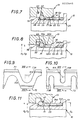
- Figures 8 and 9 show a variant implementing a decoupling member 52A having a groove 54A with a flat bottom between straight flanks formed by end edges 71, 72 having a cross section of generally triangular shape with a frustoconical bearing engagement 56A connected to the groove 54A by a cylindrical surface 56B.
- the two sections 71, 72 are each scalloped by notches 73A which, circularly alternating from one to the other of the sections, are axially nested from one to the other.
- FIG. 8 The cross-sectional structure illustrated in FIG. 8 remains in these two types of case with an operation generally equivalent to that which was considered above with reference to FIG. 7.
- the overall overall dimensions of the decoupling member being assumed unchanged, it is possible here again to provide for the formation of a few drive tongues 61A: these, as indicated simply in dotted lines, can be provided from the bottom of a few notches 73A facing the edge 71 and for reasons of symmetry one can spare as many tongues at the start of complementary notches in the direction of the edge 72 .
- the drive tongues indicated in 61A become completely useless in the embodiment illustrated in FIG. 11: this differs from the previous one in that the diameter D4 of the cylinder tangent to the vertices 56B of the end edges 71, 72 is chosen slightly greater than the internal diameter D3 of the docking piece 13. Under these conditions, it is the whole of the section 71 engaged in the docking piece which forms a positive drive means by the whole of its elements forming in a way a complete circle of tongues determined by the notches 73A and which all undergo an elastic deflection radially inwards, the clearance provided between the internal wall of the decoupling member and the bottom of the groove 53 being then increased accordingly.
- the projections 56B are of course turned in this case radially inwardly to cooperate with the external periphery of the attack piece 10 then carrying the coupling member 42.
Abstract
Dans ce montage, il est associé à l'organe de couplage (42) assurant l'attelage entre la pièce d'attaque (25) de la butée de débrayage et la pièce d'accostage (13) portée par le dispositif débrayeur de l'embrayage à commander, un organe de découplage (52) monté mobile axialement dans une gorge (53) de ladite pièce d'accostage (13).In this assembly, it is associated with the coupling member (42) ensuring the coupling between the attack piece (25) of the clutch release bearing and the docking piece (13) carried by the declutching device of the 'clutch to be controlled, a decoupling member (52) mounted axially movable in a groove (53) of said docking part (13).
Suivant l'invention, l'organe de couplage (42) étant formé par un jonc, l'organe de découplage (52) comporte annulairement une rainure (54) propre à en permettre l'accouplement débrayable avec ledit organe de couplage (42), pour réversibilité du couplage et du découplage entre la butée de débrayage et le dispositif débrayeur de l'embrayage concerné.According to the invention, the coupling member (42) being formed by a rod, the decoupling member (52) annularly has a groove (54) adapted to allow its disengageable coupling with said coupling member (42) , for reversibility of the coupling and decoupling between the clutch release bearing and the clutch release device of the clutch concerned.
Application, notamment, aux véhicules automobiles. 
Description
La présente invention concerne d'une manière générale les butées de débrayage, notamment pour véhicule automobile.The present invention relates generally to the release bearings, in particular for a motor vehicle.
Elle vise plus particulièrement celles de ces butées de débrayage qui, dites tirées, sont destinées à agir en traction sur le dispositif débrayeur de l'embrayage à commander, et qui, pour ce faire, sont attelées à celui-ci.It relates more particularly to those of these clutch release bearings which, said to be pulled, are intended to act in traction on the clutch release device of the clutch to be controlled, and which, to do this, are coupled to the latter.
Il a été proposé, à cet effet, dans certains montages de butée de débrayage, et c'est le cas, notamment, tant dans le montage de butée de débrayage décrit dans le brevet français déposé le 19 Mars 1975 sous le No 75 08514 et publié sous le No 2.304.826 que dans celui décrit dans le brevet français déposé le 27 Décembre 1983 sous le No 83 20829 et publié sous le No 2.557.234, de mettre en oeuvre, entre la butée de débrayage et le dispositif débrayeur à commander, pour l'attelage de cette butée de débrayage à ce dispositif débrayeur, une pièce, dite ici par simple commodité "pièce d'accostage", ou "pièce d'action", qui, convenablement rapportée sur ledit dispositif débrayeur, comporte radialement, du côté de celui-ci opposé à la butée de débrayage, une collerette d'appui par laquelle elle est apte à agir sur lui, en coopération avec des moyens de solidarisation en traction, qui, établis entre une telle pièce d'accostage et une pièce, dite ici par simple commodité "pièce d'attaque", appartenant à la butée de débrayage, sont propres à assurer une liaison axiale entre lesdites pièces dans le sens axial allant du dispositif débrayeur à la butée de débrayage.It has been proposed, for this purpose, in certain release bearing arrangements, and this is the case, in particular, both in the release bearing arrangement described in the French patent filed on March 19, 1975 under No. 75 08514 and published under No 2,304,826 as in that described in the French patent filed on December 27, 1983 under No 83 20829 and published under No 2.557.234, to implement, between the clutch release bearing and the declutching device to be controlled , for the coupling of this clutch release bearing to this declutching device, a part, here called for simple convenience "docking part", or "action part", which, suitably attached to said declutching device, comprises radially, on the side thereof opposite the clutch release bearing, a support flange by which it is able to act on it, in cooperation with means for securing in traction, which, established between such a docking piece and a piece, called here simply for convenience "attack piece", appears attached to the clutch release bearing, are suitable for ensuring an axial connection between said parts in the axial direction from the clutch release device to the clutch release bearing.
En pratique, dans les brevets français mentionnés ci-dessus, les moyens de solidarisation en traction mis en oeuvre comportent, d'une manière générale, d'une part, un organe de couplage annulaire élastiquement déformable radialement, par exemple un simple jonc, qui est au moins partiellement engagé radialement dans une gorge annulaire de retenue ménagée pour lui sur l'une quelconque des pièces à solidariser en traction, et, d'autre part, une portée d'entraînement, qui est ménagée globalement transversalement sur l'autre de ces pièces, et avec laquelle ledit organe de couplage coopère axialement en appui dans le sens axial correspondant à la liaison axiale recherchée.In practice, in the French patents mentioned above, the traction securing means used generally comprise, on the one hand, an elastically radially deformable annular coupling member, for example a simple rod, which is at least partially engaged radially in an annular retaining groove made for it on any of the parts to fasten in traction, and, on the other hand, a drive surface, which is provided generally transversely to the other of these parts, and with which said coupling member cooperates axially bearing in the axial direction corresponding to the axial connection wanted.
Une telle disposition a notamment pour avantage de permettre d'équiper par avance de la pièce d'accostage le dispositif débrayeur de l'embrayage à commander, avant même l'assemblage du mécanisme d'embrayage correspondant, et d'assurer ensuite, lors de l'assemblage de l'ensemble, la venue en prise par simple encliquetage de la butée de débrayage avec ladite pièce d'accostage, et donc avec ledit dispositif débrayeur.The advantage of such an arrangement is that it allows the clutch release device to be controlled to be fitted in advance with the docking part, even before the corresponding clutch mechanism is assembled, and then, when the assembly of the assembly, the engagement by simple snap-fastening of the clutch release bearing with said docking part, and therefore with said declutching device.
Si le couplage recherché entre la butée de débrayage et le dispositif débrayeur de l'embrayage à commander se trouve ainsi très aisément assuré, il n'en est pas de même, sans autre, pour le processus inverse, c'est-à-dire pour le processus nécessaire pour assurer un découplage entre cette butée de débrayage et ce dispositif débrayeur.If the desired coupling between the clutch release bearing and the clutch disengaging device to be controlled is thus very easily ensured, it is not the same, without other, for the reverse process, that is to say for the process necessary to ensure decoupling between this clutch release bearing and this clutch release device.
Sans autre, il faut en effet normalement procéder au préalable au démontage de l'embrayage, pour avoir accès de l'avant, c'est-à-dire du côté du dispositif débrayeur, sur l'organe de couplage, et être ainsi en mesure d'en provoquer l'effacement élastique nécessaire au découplage recherché.Without other, it is indeed normally necessary to disassemble the clutch beforehand, in order to have access from the front, that is to say on the side of the declutching device, on the coupling member, and thus be in measure to cause the elastic erasure necessary for the desired decoupling.
Pour pallier cette difficulté, il a été proposé, dans le brevet français No 83 20829 mentionné ci-dessus, de mettre en oeuvre, pour la délimitation de la gorge de retenue, une pièce mobile, en pratique en forme de douille, dite pièce de désolidarisation, qui est normalement axialement à distance de l'organe de couplage et qu'il suffit de déplacer axialement en direction de cet organe de couplage pour le chasser hors de ladite gorge de retenue et ainsi assurer le découplage recherché.To overcome this difficulty, it has been proposed, in the French patent No. 83 20829 mentioned above, to implement, for the delimitation of the retaining groove, a movable part, in practice in the form of a socket, known as detachment, which is normally axially distant from the coupling member and which suffices to move axially in the direction of this coupling member to drive it out of said retaining groove and thus ensure the desired decoupling.
Bien que donnant satisfaction, une telle disposition présente des difficultés.Although satisfactory, such a provision presents difficulties.
En particulier, un outil est nécessaire pour la manoeuvre de la pièce de désolidarisation, ce qui rend relativement malaisée cette manoeuvre.In particular, a tool is necessary for the operation of the separation piece, which makes relatively difficult this maneuver.
Dans la demande de brevet européen déposée le 10 Novembre 1983 sous le No 83306880.2 et publiée sous le No 0 110 602, il est décrit une disposition dont il résulte au contraire, que, tant pour le découplage que pour le couplage, il suffit d'appliquer un mouvement axial relatif approprié à la butée de débrayage par rapport au dispositif débrayeur de l'embrayage à commander, le mouvement axial ainsi à appliquer à cette butée de débrayage pouvant très simplement lui être imprimé, en aveugle, à l'aide de l'organe de commande, en pratique une fourchette de débrayage, qui lui est usuellement associé.In the European patent application filed on November 10, 1983 under No. 83306880.2 and published under No. 0 110 602, there is described a provision from which it follows, on the contrary, that, both for decoupling and for coupling, it suffices to apply a relative axial movement suitable for the clutch release bearing with respect to the clutch disengaging device to be controlled, the axial movement thus to be applied to this clutch release bearing being able to be very simply printed to it, blind, using the 'control member, in practice a clutch release fork, which is usually associated therewith.
Suivant cette disposition, il est associé à l'organe de couplage un organe annulaire de découplage, qui est mis en place par avance sur celle des pièces à solidariser en traction qui comporte la portée d'entraînement, à distance de celle-ci, et avec lequel, en réponse à un mouvement axial suffisant de la butée de débrayage dans le sens axialement tourné en direction opposée à ladite portée d'entraînement, peut venir en prise ledit organe de couplage, moyennant une mise sous contrainte de celui-ci.According to this arrangement, there is associated with the coupling member an annular decoupling member, which is put in place ahead of that of the parts to be joined in traction which comprises the drive range, at a distance therefrom, and with which, in response to sufficient axial movement of the clutch release bearing in the direction axially turned in the direction opposite to said drive surface, can engage said coupling member, by means of a constraint thereof.
L'organe de couplage étant ainsi mis sous contrainte par l'organe de découplage, il entraîne avec lui ce dernier si la butée de débrayage est à nouveau l'objet d'un déplacement axial dans le sens axial tourné vers la portée d'entraînement, mais, du fait même de sa mise sous contrainte, il échappe alors à cette portée d'entraînement, ce qui conduit effectivement au découplage recherché.The coupling member being thus put under stress by the decoupling member, it drives with it the latter if the clutch release bearing is again the object of an axial displacement in the axial direction turned towards the drive surface , but, by the very fact of being put under stress, it then escapes this drive range, which effectively leads to the desired decoupling.
Mais, dans le même mouvement, entraîné qu'il est par l'organe de couplage, l'organe de découplage échappe lui-même alors à la piece qu'il équipait initialement, et tout nouveau couplage est impossible, sauf à désolidariser au préalable l'organe de découplage de l'organe de couplage, et à remettre à leur place initiale l'un et l'autre de ces organes, ou tous nouveaux organes neufs propres à leur être substitués, ce qui relève en pratique d'opérations particulièrement malaisées à conduire.But, in the same movement, driven as it is by the coupling member, the decoupling member itself escapes from the part that it originally fitted, and any new coupling is impossible, unless it is disconnected beforehand the decoupling member of the coupling member, and to return to their original place both of these members, or any new new members capable of being substituted for them, which is in practice operational particularly difficult to drive.
Or, sur les chaînes de montage des véhicules concernés, il peut au contraire être avantageux de pouvoir procéder à un nouveau couplage après un découplage.However, on the assembly lines of the vehicles concerned, it may on the contrary be advantageous to be able to carry out a new coupling after decoupling.
En effet, après le couplage de la butée de débrayage sur le dispositif débrayeur de l'embrayage à équiper, d'autres opérations de montage sont à assurer sur de telles chaînes de montage, et, par exemple, le branchement du câble d'embrayage propre à la commande de l'ensemble, et, au cours de telles opérations, une action fortuite sur la fourchette de débrayage peut entraîner de mainère intempestive un découplage de la butée de débrayage.In fact, after coupling the clutch release bearing on the clutch release device of the clutch to be fitted, other assembly operations must be carried out on such assembly lines, and, for example, the connection of the clutch cable. specific to the control of the assembly, and, during such operations, a fortuitous action on the declutching fork may inadvertently lead to decoupling of the declutching stop.
Dans la demande de brevet français déposée le 28 Juin 1985 sous le No 85 09883, il a été proposé une disposition permettant de manière particulièrement simple et avantageuse de procéder de façon réversible à un couplage et/ou à un découplage.In the French patent application filed on June 28, 1985 under No. 85 09883, a provision was proposed which makes it possible, in a particularly simple and advantageous manner, to carry out a reversible coupling and / or decoupling.
Suivant cette disposition, il est associé à l'organe de couplage un organe annulaire de découplage, comme précédemment, mais cet organe de découplage est monté mobile axialement dans une gorge à laquelle il ne peut échapper.According to this arrangement, there is associated with the coupling member an annular decoupling member, as previously, but this decoupling member is mounted axially movable in a groove from which it cannot escape.
En pratique, cette gorge est ménagée dans celle des pièces à solidariser en traction qui comporte la portée d'entraînement, et ladite portée d'entraînement appartient à l'un de ses flancs.In practice, this groove is formed in that of the parts to be secured in traction which comprises the drive range, and said drive range belongs to one of its sides.
Conjointement, l'organe de découplage se trouve présenter un portée tronconique qui va en s'écartant radialement du fond de la gorge dans laquelle il est disposé, en direction de la portée d'entraînement, et dont la circonférence axialement la plus proche de ladite portée d'entraînement est au moins à niveau avec la circonférence formant le bord libre de celle-ci.Jointly, the decoupling member is found to have a frustoconical bearing which goes away radially from the bottom of the groove in which it is arranged, in the direction of the driving bearing, and whose circumference axially closest to said drive range is at least level with the circumference forming the free edge thereof.
Lorsqu'un découplage est recherché, il suffit, comme précédemment, d'agir sur la butée de débrayage de manière à ce que l'organe de couplage vienne en prise avec l'organe de découplage.When a decoupling is sought, it suffices, as previously, to act on the declutching stop so that the coupling member comes into engagement with the decoupling member.
Mais, cette venue en prise de l'organe de couplage avec l'organe de découplage se fait par la portée tronconique de ce dernier, en sorte que, lorsque, pour le découplage recherché, la butée de débrayage est à nouveau déplacée axialement dans le sens axial tourné vers la portée d'entraînement, l'organe de découplage, qui vient en butée contre cette dernière provoque, par sa dite portée tronconique, et tout en restant en place au sein de la pièce qu'il équipe, une rétraction de l'organe de couplage suffisante pour que celui-ci puisse échapper tant à cet organe de découplage qu'à ladite portée d'entraînement, et, par là, à la pièce conportant cette portée d'entraînement.However, this engagement of the coupling member with the decoupling member is effected by the frustoconical bearing of the latter, so that, when, for the desired decoupling, the clutch release bearing is again displaced axially in the axial direction facing the drive range, the decoupling member, which abuts against the latter causes, by its so-called frustoconical range, and while remaining in place within the part which it equips, a retraction of the coupling member sufficient for it to be able to escape both from this decoupling member and from said drive range, and thereby the part containing this drive range.
L'organe de découplage étant demeuré en place, un nouveau couplage est possible.The decoupling member having remained in place, a new coupling is possible.
Mais, en pratique, la disposition ainsi décrite dans la demande de brevet français No 85 09883 en question ne convient qu'au cas où l'organe de couplage est du type d'un de ceux décrits dans le brevet français No 75 08514 également mentionné ci-dessus, c'est-à-dire au cas où cet organe de couplage comporte une rondelle globalement tronconique, qui, par l'une de ses périphéries, est engagée dans la gorge de retenue associée, et qui présente, le long de son autre périphérie, d'une part, sensiblement dans son prolongement, des pattes par laquelles elle est adaptée à coopérer axialement en appui avec la portée d'entraînement, et, d'autre part, des pattes, qui, faisant un angle avec les précédentes, sont elles aussi engagées dans la gorge de retenue, du côté opposé à la rondelle globalement tronconique dont elles sont issues.However, in practice, the arrangement thus described in the French patent application No 85 09883 in question is only suitable if the coupling member is of the type of one of those described in French patent No 75 08514 also mentioned. above, that is to say in the case where this coupling member comprises a generally frustoconical washer, which, through one of its peripheries, is engaged in the associated retaining groove, and which has, along its other periphery, on the one hand, substantially in its extension, lugs by which it is adapted to cooperate axially in abutment with the drive surface, and, on the other hand, lugs, which, at an angle with the previous, are also engaged in the retaining groove, on the side opposite to the generally frustoconical washer from which they originate.
Mais elle ne convient pas au cas où l'organe de couplage est un simple jonc, c'est-à-dire au cas où cet organe de couplage se présente sous la forme d'un tore, et, par exemple, sous la forme d'un tore de section transversale circulaire.But it is not suitable in the case where the coupling member is a simple rod, that is to say in the case where this coupling member is in the form of a torus, and, for example, in the form of a torus of circular cross section.
La présente invention a au contraire d'une manière générale pour objet une disposition adaptée à un tel cas.The present invention, on the contrary, generally relates to a provision adapted to such a case.
De manière plus précise, elle a pour objet un montage de butée de débrayage, du genre comportant, pour l'attelage d'une butée de débrayage au dispositif débrayeur d'un embrayage, une pièce, dite ici par commodité pièce d'accostage, qui est convenablement rapportée sur ledit dispositif débrayeur, et des moyens de solidarisation en traction, qui, établis entre la pièce d'accostage et une pièce, dite ici par commodité pièce d'attaque, appartenant à la butée de débrayage, sont propres à assurer une liaison axiale entre lesdites pièces dans le sens axial allant du dispositif débrayeur à ladite butée de débrayage, lesdits moyens de solidarisation en traction comportant, d'une part, un organe annulaire de couplage, élastiquement déformable radialement, qui est au moins partiellement engagé radialement dans une gorge annulaire de retenue ménagée pour lui sur l'une quelconque desdites pièces, et, d'autre part, une portée d'entraînement, qui est ménagée globalement transversalement sur l'autre de celles-ci, et avec laquelle ledit organe de couplage est apte à coopérer axialement en appui dans le sens axial considéré, et du genre comportant également, pour le découplage de la butée de débrayage par rapport au dispositif débrayeur de l'embrayage concerné, un organe annulaire de découplage monté mobile axialement dans une gorge, qui est ménagée pour lui sur celle des pièces comportant la portée d'entraînement, et dont ladite portée d'entraînement appartient à l'un des flancs, ce montage de butée de débrayage étant d'une manière générale caractérisé en ce que, l'organe de couplage étant formé par un jonc, l'organce de découplage comporte annulairement, tournée vers la gorge de retenue, une rainure propre à en permettre l'accouplement débrayable avec ledit organe de couplage, au moins pour le sens axial allant du dispositif débrayeur à la butée de débrayage.More specifically, it relates to a mounting of a clutch release bearing, of the type comprising, for coupling a clutch release bearing to the declutching device of a clutch, a part, called here for convenience, docking piece, which is suitably attached to said declutching device, and means for securing in traction, which, established between the docking part and a part, here called for convenience attack part, belonging to the clutch release bearing, are suitable for ensuring an axial connection between said parts in the axial direction going from the declutching device to said declutching stop, said traction securing means comprising, on the one hand, an annular coupling member, elastically deformable radially, which is at least partially engaged radially in an annular retaining groove formed for it on the 'any one of said parts, and, on the other hand, a drive surface, which is formed generally transversely over the other thereof, and with which said coupling member is capable of cooperating axially in abutment in the axial direction considered, and of the kind also comprising, for the decoupling of the clutch release bearing with respect to the clutch disengaging device concerned, an annular decoupling member mounted to move axially in a groove, which is arranged for him on that of the parts comprising the drive range, and of which said drive range belongs to one of the sides, this clutch release bearing assembly being generally characterized in that, the the coupling member being formed by a rod, the decoupling device annularly comprises, turned towards the retaining groove, a groove capable of allowing it to be disengageable coupling with said coupling member, at least for the axial direction going from the disengaging device to the clutch release bearing.
Grâce à une telle disposition, et comme précédemment, le découplage peut avantageusement résulter d'un simple déplacement axial, en aveugle, de la butée de débrayage, d'abord dans un sens, puis en sens opposé, et après un tel découplage, il est avantageusement possible de procéder de manière réversible à un nouveau couplage.Thanks to such an arrangement, and as before, decoupling can advantageously result from a simple axial displacement, blind, of the clutch release bearing, first in one direction, then in opposite direction, and after such decoupling, is advantageously possible to proceed from reversible way to a new coupling.
En outre, se présentant sous un volume relativement modest, l'organe de découplage ainsi intégré à un tel montage de butée de débrayage ne conduit avantageusement à aucune augmentation sensible de l'encombrement axial ou diamétral de l'une ou l'autre des pièces concernées de celui-ci.In addition, being presented in a relatively modest volume, the decoupling member thus integrated into such a release bearing assembly advantageously does not lead to any appreciable increase in the axial or diametral size of one or the other of the parts. concerned with it.
Les caractéristiques et avantages de l'invention ressortiront d'ailleurs de la description qui va suivre, à titre d'exemple, en référence aux dessins schématiques annexés sur lesquels :
- la figure 1 est une vue en coupe axiale d'un montage de butée de débrayage mettant en oeuvre un organe de découplage suivant l'invention ;
- la figure 2 reprend, à échelle supérieure, le détail de la figure 1 repéré par un encart II sur celle-ci ;
- la figure 3 est, à échelle différente, une vue partielle en élévation de l'organe de couplage mis en oeuvre dans ce montage de butée de débrayage, suivant la flèche III de la figure 2 ;
- la figure 4 est une vue partielle en coupe axiale de cet organe de découplage, suivant la ligne IV-IV de la figure 3 ;
- les figures 5A, 5B, 5C, 5D, 5E sont des vues qui, reprenant celle de la figure 2, illustrent le couplage de la butée de débrayage concernée avec la pièce d'accostage portée par le dispositif débrayeur de l'embrayage à commander ;
- les figures 6A, 6B, 6C, 6D, 6E sont des vues qui, reprenant également celle de la figure 2, illustrent au contraire le découplage de cette butée de débrayage par rapport à la pièce d'accostage portée par le dispositif débrayeur de cet embrayage ;
- la figure 7 est une vue qui, analogue elle aussi à celle de la figure 2, se rapporte à une variante de réalisation de l'invention ;
- la figure 8 est une vue semblable à celle de la figure 7 mais relative à une variante de réalisation mettant en oeuvre un organe de découplage non fendu, cet organe étant montré en coupe selon le plan VIII-VIII de la figure 9 ou 10 ;
- les figures 9 et 10 sont des vues partielles en plan de deux formes de réalisation d'une telle variante ;
- la figure 11 est une vue semblable à celle de la figure 8 relative à un autre mode de mise en oeuvre d'un organe de découplage de type analogue.
- Figure 1 is an axial sectional view of a clutch release bearing assembly using a decoupling member according to the invention;
- Figure 2 shows, on a larger scale, the detail of Figure 1 identified by an insert II thereon;
- Figure 3 is, on a different scale, a partial elevational view of the coupling member used in this clutch release bearing assembly, according to arrow III of Figure 2;
- Figure 4 is a partial view in axial section of this decoupling member, along the line IV-IV of Figure 3;
- FIGS. 5A, 5B, 5C, 5D, 5E are views which, taking again that of FIG. 2, illustrate the coupling of the declutch release bearing concerned with the docking part carried by the clutch release device of the clutch to be controlled;
- FIGS. 6A, 6B, 6C, 6D, 6E are views which, also taking that of FIG. 2, illustrate on the contrary the decoupling of this clutch release bearing with respect to the docking part carried by the clutch release device of this clutch ;
- Figure 7 is a view which, also similar to that of Figure 2, relates to an alternative embodiment of the invention;
- Figure 8 is a view similar to that of Figure 7 but relating to an alternative embodiment using a non-split decoupling member, this member being shown in section along the plane VIII-VIII of Figure 9 or 10;
- Figures 9 and 10 are partial plan views of two embodiments of such a variant;
- Figure 11 is a view similar to that of Figure 8 relating to another embodiment of a decoupling member of similar type.
Tel qu'illustré par la figure 1, il s'agit d'atteler une butée de débrayage 10 au dispositif débrayeur 11 d'un quelconque embrayage à commander.As illustrated in FIG. 1, this involves coupling a clutch release bearing 10 to the clutch release device 11 of any clutch to be controlled.
Dans les formes de réalisation représentées, le dispositif débrayeur 11 est, de manière connue en soi, formé par l'extrémité des doigts radiaux d'un diaphragme, c'est-à-dire d'une pièce annulaire, qui, appartenant à l'embrayage à commander, comporte une partie périphérique circulairement continue, formant rondelle Belleville, pour sollicitation en engagement de cet embrayage, et une partie centrale fragmentée en doigts radiaux par des fentes, à savoir les doigts radiaux en question, pour constitution de leviers propres à sa commande en dégagement.In the embodiments shown, the declutching device 11 is, in a manner known per se, formed by the end of the radial fingers of a diaphragm, that is to say of an annular part, which, belonging to the clutch to be controlled, comprises a circularly continuous peripheral part, forming a Belleville washer, for biasing engagement of this clutch, and a central part fragmented into radial fingers by slots, namely the radial fingers in question, for constituting levers suitable for his clearance order.
De manière également connue en soi, pour l'attelage de la butée de débrayage 10 au dispositif débrayeur 11, nécessaire à une action en traction de cette butée de débrayage 10 sur ce dispositif débrayeur 11, il est rapporté sur ce dernier, à la faveur de son ouverture centrale 12, une pièce 13, dite ici par commodité pièce d'accostage.In a manner also known per se, for the coupling of the declutching
Dans les formes de réalisation représentées, cette pièce d'accostage, ou pièce d'action, est du type de celle décrite dans la demande de brevet français déposée le 11 Avril 1983, sous le No 83 05850, et publiée sous le No 2.544.036.In the embodiments shown, this docking part, or action part, is of the type described in the French patent application filed on April 11, 1983, under No. 83 05850, and published under No. 2.544. 036.
Une telle pièce d'accostage ne faisant pas partie de la présente invention, elle ne sera pas décrite en détail ici.Since such a docking part is not part of the present invention, it will not be described in detail here.
Il suffira d'indiquer que, du côté du dispositif débrayeur 11 opposé à la butée de débrayage 10, elle comporte radialement une collerette 14, dite collerette d'appui, pour action sur un tel dispositif débrayeur 11, ladite collerette d'appui étant convenablement profilée à cet effet, et que, d'un seul tenant avec cette collerette d'appui 14, elle comporte, d'une part, à sa périphérie interne, une douille 15, qui, s'étendant globalement axialement, traverse axialement ledit dispositif débrayeur 11, à la faveur de l'ouverture centrale 12 de celui-ci, et, d'autre part, à sa périphérie externe, de place en place le long de celle-ci, des pattes 16, qui traversent également axialement le dispositif débrayeur 11, chacune entre deux doigts radiaux adjacents de celui-ci, et qui, chacune respectivement, portent, circonférentiellement, en porte-à-faux, à leur extrémité, au droit de la collerette d'appui 14, et globalement parallèlement à celle-ci, des doigts de retenue 17 propres à assurer, en coopération avec cette collerette d'appui 14, le maintien axial de l'ensemble sur le dispositif débrayeur 11.It will suffice to indicate that, on the side of the device declutcher 11 opposite the
Tel que décrit dans la demande de brevet français No 83 05850 mentionnée ci-dessus, la mise en place d'une telle pièce d'accostage 13 sur le dispositif débrayeur 11 se fait suivant un montage du type à baïonnette : après un rapprochement relatif suffisant de la pièce d'accostage 13 et du dispositif débrayeur 11, on assure, axialement, une flexion relative, vis-à-vis des autres, de l'extrémité de chacun des doigts radiaux du dispositif débrayeur 11 sur lequel doit circonférentiellement s'engager le doigt de retenue 17 des pattes 16 de la pièce d'accostage 13, puis on assure, circonférentiellement, une rotation relative, autour de l'axe de l'ensemble, de ladite pièce d'accostage 13 vis-à-vis dudit dispositif débrayeur 11, pour qu'un tel engagement ait effectivement lieu, et on libère ensuite les doigts radiaux précédemment fléchis du dispositif débrayeur 11.As described in the French patent application No. 83 05850 mentioned above, the installation of such a
Dans les formes de réalisation représentées, la douille axiale 15 de la pièce d'accostage 13 s'étend globalement de manière rectiligne.In the embodiments shown, the
A son extrémité libre, elle est, à sa périphérie interne, chanfreinée, et elle forme ainsi, pour des raisons qui apparaîtront ci-après, une portée tronconique d'engagement 18.At its free end, it is, at its internal periphery, chamfered, and it thus forms, for reasons which will appear below, a
La butée de débrayage 10 ne fait pas non plus, en soi, partie de la présente invention.The clutch release bearing 10 is also not, per se, part of the present invention.
De manière connue en soi, elle comporte, globalement, un élément d'attaque 20, par lequel elle est adaptée à agir sur le dispositif débrayeur 11, par l'intermédiaire de la pièce d'accostage 13, tel que détaillé ci-après, un élément de manoeuvre 22, par lequel elle est destinée, dans les formes de réalisation représentées, et tel que schématisé en traits interrompus sur la figure 1, à être montée coulissante axialement sur un quelconque organe de guidage 23, et par lequel, et tel que également schématisé en traits interrompus sur cette figure 1, elle est par ailleurs adaptée à être actionnée par un organe de commande 24, constitué, par exemple, par une fourchette de débrayage à doigts ou bras 21, et des moyens d'attelage assujettissant axialement ledit élément d'attaque 20 audit élément de manoeuvre 22.In a manner known per se, it comprises, overall, a driving
Dans les formes de réalisation représentées, l'élément d'attaque 20 est constitué par un roulement à billes.In the embodiments shown, the driving
Pour coopération avec la pièce d'accostage 13, celui-ci comporte une pièce 25, dite ici par commodité pièce d'attaque.For cooperation with the
Dans les formes de réalisation représentées, cette pièce d'attaque 25 est constituée par la bague interne de ce roulement à billes, celle-ci étant suffisamment prolongée axialement à cet effet en direction du dispositif débrayeur 11.In the embodiments shown, this leading
Conjointement, dans les formes de réalisation représentées, l'élément de manoeuvre 22 comporte, axialement, un manchon 26, par lequel il est adapté à être engagé à coulissement sur l'organe de guidage 23, et, transversalement, d'une part, à une première extrémité dudit manchon 26, un flasque annulaire 27, pour coopération avec l'élément d'attaque 20, et, d'autre part, à l'autre extrémité de ce manchon 26, deux bras 28, pour action de l'organe de commande 24.Jointly, in the embodiments shown, the operating
Pour des raisons qui apparaîtront ci-après, l'élément de manoeuvre 22 comporte, en outre, parallèlement aux bras 28, à distance de ceux-ci, des bras 29, en sorte que chacun des doigts 21 de l'organe de commande 24 est encadré, d'un côté, par un bras 28 de l'organe de manoeuvre 22, et, de l'autre côté, par un bras 29 de celui-ci.For reasons which will appear below, the operating
Dans les formes de réalisation représentées, les moyens d'attelage assujettissant axialement l'élément d'attaque 20 à l'élément de manoeuvre 22 sont constitués par un capot 30, qui, engagé par des ouvertures 31 sur des ergots 32 qui présente radialement en saillie à la périphérie de son flasque 27 l'élément de manoeuvre 22, et ainsi solidaire axialement de celui-ci, s'étend au-delà de la bague externe 33 du roulement à billes constituant l'élément d'attaque 20, et comporte, au bout de cette bague externe 33, un retour en équerre 34, dirigé radialement en direction de l'axe de l'ensemble.In the embodiments shown, the coupling means axially securing the driving
S'agissant, en pratique, dans les formes de réalisation représentées, d'une butée de débrayage autocentreuse à autocentrage maintenu, un jeu est laissé annulairement entre le capot 30 et le roulement à billes constituant l'élément d'attaque 20, et, entre la bague externe 33 de ce dernier et l'élément de manoeuvre 22, interviennent des moyens élastiques à action axiale constitués, par exemple, tel que représenté, par une rondelle ondulée 35 du type de celle vendue sous la dénomination commerciale "ONDUFLEX".As regards, in practice, in the embodiments shown, a self-centering declutching stop with self-centering maintained, a clearance is left annularly between the
Cette rondelle ondulée 35 sollicite axialement le roulement à billes constituant l'élément d'attaque 20 en direction du retour en équerre 34 du capot 30, pour coopération avec celui-ci par la tranche correspondante de sa bague externe 33.This
En pratique, dans les formes de réalisation représentées, entre cette bague externe 33 et ce retour en équerre 34 est interposée une rondelle de frottement 37.In practice, in the embodiments shown, between this
Enfin, dans les formes de réalisation représentées, et pour des raisons qui apparaîtront ci-après, la pièce d'attaque 25 de l'élément d'attaque 20 porte, radialement, en saillie sur sa périphérie externe, dans sa zone médiane, une rondelle d'arrêt 39, par exemple une rondelle ouverte radialement par une fente, en prise avec elle par une gorge 40 prévue à cet effet sur sa dite périphérie externe.Finally, in the embodiments shown, and for reasons which will appear below, the
Ces dispositions étant bien connues par elles-mêmes, et ne faisant pas partie de la présente invention, elles ne seront pas décrites plus en détail ici.These arrangements being well known in themselves, and not forming part of the present invention, they will not be described in more detail here.
De manière également connue en soi, entre la pièce d'attaque 25 de la butée de débrayage 10 ainsi constituée, d'une part, et la pièce d'accostage 13 portée par le dispositif débrayeur 11, d'autre part, sont établis des moyens de solidarisation en traction propres à assurer une liaison axiale entre lesdites pièces dans le sens axial qui, tel que schématisé par la flèche F1 sur la figure 1, va du dispositif débrayeur 11 à la butée de débrayage 10.In a manner also known per se, between the
La pièce d'accostage 13 comportant axialement une douille 15, et celle-ci étant coaxiale de la pièce d'attaque 25, c'est entre cette douille 15 et cette pièce d'attaque 25 que sont établis lesdits moyens de solidarisation en traction.The
Plus précisément, dans les formes de réalisation représentées, la pièce d'attaque 25 est engagée dans la douille 15 de la pièce d'accostage 13, en sorte que les moyens de solidarisation en traction en question interviennent entre la périphérie externe de cette pièce d'attaque 25 et la périphérie interne de cette douille 15.More precisely, in the embodiments shown, the leading
De manière générale, ils comportent, figures 1 et 2, d'une part, un organe annulaire de couplage 42, qui est élastiquement déformable radialement, et qui est au moins partiellement engagé radialement dans une gorge annulaire de retenue 43 ménagée pour lui sur l'une quelconque des pièces 13, 25 en cause, et, d'autre part, une portée d'entraînement 44, qui est ménagée globalement transversalement sur l'autre desdites pièces 13, 25, et avec laquelle il est apte à coopérer axialement en appui dans le sens axial considéré, celui repéré par la flèche F1 sur la figure 1.In general, they comprise, Figures 1 and 2, on the one hand, an
En pratique, dans la forme de réalisation plus particulièrement représentée sur les figures 1 à 6, la gorge de retenue 43 est formée sur la pièce d'attaque 25, au voisinage de l'extrémité libre de celle-ci, tandis que la portée d'entraînement 44 est formée sur la douille 15 de la pièce d'accostage 13.In practice, in the embodiment more particularly shown in FIGS. 1 to 6, the retaining
En outre, l'organe de couplage 42 est formé par un simple jonc.In addition, the
Par exemple, il s'agit d'une pièce de forme générale torique, ouverte radialement par une fente.For example, it is a generally toroidal part, opened radially by a slot.
Dans la forme de réalisation représentée, le jonc formant ainsi l'organe de couplage 42 a, axialement, une section transversale circulaire, ce jonc étant par exemple réalisé par roulage d'un fil rond.In the embodiment shown, the rod thus forming the
Quoi qu'il en soit, à l'état libre, figure 5A, il occupe une configuration déployée pour laquelle son diamètre intérieur D1 est inférieur à celui D2 de la périphérie externe de la pièce d'attaque sur laquelle est ménagée la gorge de retenue 43 correspondante.Anyway, in the free state, FIG. 5A, it occupies a deployed configuration for which its internal diameter D1 is less than that D2 of the external periphery of the attack piece on which the retaining groove is formed. 43 corresponding.
Mais, du fait de la fente qu'il comporte, il peut prendre une configuration rétractée, figure 5C par exemple, pour laquelle son engagement radial dans cette gorge de retenue 43 est accentué.However, because of the slot which it comprises, it can take a retracted configuration, FIG. 5C for example, for which its radial engagement in this retaining
En pratique, dans la forme de réalisation représentée, le flanc 46 de la gorge de retenue 43 tourné axialement du même côté que la portée d'entraînement 44 est droit.In practice, in the embodiment shown, the
Mais, suivant l'invention, et pour des raisons qui apparaîtront ci-après, le flanc 47 de cette gorge de retenue 43 opposé à la portée d'entraînement 44 présente, au contraire, dans la forme de réalisation représentée, à compter du fond de cette gorge de retenue 43, une première portée tronconique 48, et, faisant suite à celle-ci, une deuxième portée tronconique 49, qui est de conicité plus faible que celle de la précédente, et qui s'étend en pratique jusqu'à la périphérie externe de la pièce d'attaque 25 concernée.However, according to the invention, and for reasons which will appear below, the flank 47 of this retaining
Ainsi donc, dans la forme de réalisation représentée, du côté de son flanc 47, la gorge de retenue 43 va en s'évasant vers l'extérieur, de son fond à la périphérie externe de la pièce d'attaque 25.Thus, in the embodiment shown, on the side of its side 47, the retaining
A son extrémité libre, la pièce d'attaque 25 est chanfreinée, comme la douille 15 de la pièce d'accostage 13, et elle présente donc elle aussi, pour des raisons qui apparaîtront ci-après, une portée tronconique 50.At its free end, the leading
De manière connue en soi, il est prévu en outre un organe annulaire de découplage 52.In a manner known per se, an
Cet organe de découplage 52 est monté mobile axialement dans une gorge 53, qui est ménagée pour lui sur celle des pièces 13, 25 comportant la portée d'entraînement 44, et il s'agit donc, en l'espèce, dans la forme de réalisation représentée, de la pièce d'accostage 13, et dont ladite portée d'entraînement 44 appartient à l'un des flancs.This
En pratique, cette gorge 53 ouvre sur la périphérie interne de la douille 15 de la pièce d'accostage 13, laquelle a un diamètre D3 légèrement supérieur à celui D2 de la périphérie externe de la pièce d'attaque 25.In practice, this
Suivant l'invention, l'organe de couplage 42 étant formé, comme indiqué ci-dessus, par un simple jonc, l'organe de découplage 52 comporte, annulairement, tournée vers la gorge de retenue 43, et donc, dans la forme de réalisation représentée, sur sa périphérie interne, une rainure 54 propre à en permettre l'accouplement débrayable avec ledit organe de couplage 42, au moins pour le sens axial allant du dispositif débrayeur 11 à la butée de débrayage 10.According to the invention, the
En pratique, dans la forme de réalisation représentée, cette rainure 54 de l'organe de découplage 52 a, axialement, un profil au moins en partie complémentaire de celui de l'organe de couplage 42, et il s'agit donc, en l'espèce, d'un profil en portion de cercle.In practice, in the embodiment shown, this
En pratique, l'organe de découplage 52 se présente sous la forme générale d'un anneau relativement plat, et, dans la forme de réalisation représentée, sa rainure 54 s'étend sensiblement dans la zone médiane de sa périphérie interne.In practice, the
Du côté de cette rainure 54 axialement opposée à la portée d'entraînement 44, la périphérie interne de l'organe de découplage 52 forme une portée cylindrique 55.On the side of this
Mais, du côté opposé, c'est-à-dire du côté de la portée d'entraînement 44, l'organe de découplage 52 comporte, sur sa périphérie interne, en liaison avec sa rainure 54, une portée tronconique d'engagement 56, dont la concavité est tournée vers ladite portée d'entraînement 44, et qui, dans la forme de réalisation représentée, se raccorde à ladite rainure 54 par une arête 57.However, on the opposite side, that is to say on the side of the
Quant à la périphérie externe de l'organe de découplage 52, elle forme, uniment, dans sont ensemble, une portée globalement cylindrique 58.As for the external periphery of the
Ainsi, si, du côté axialement opposé à la portée d'entraînement 44, l'organe de découplage 52 a, transversalement, un profil droit, il a, du côté de cette portée d'entraînement 44, un profil globalement triangulaire.Thus, if, on the side axially opposite to the driving
Dans la forme de réalisation représentée, l'organe de découplage 52 présente, axialement, au moins une languette 60, dite ci-après par simple commodité languette d'entraînement, qui est élastiquement déformable radialement, et dont l'extrémité libre 61, au repos, fait radialement saillie sur celle des ses périphéries qui, tournée vers la gorge de retenue 43, présente une rainure 54, et il s'agit en l'espèce, dans la forme de réalisation représentée, et tel que précisé ci-dessus, de sa périphérie interne.In the embodiment shown, the
De préférence, et tel que représenté, l'extrémité libre 61 d'une telle languette d'entraînement 60 est axialement à distance de la rainure 54, en s'étendant du côté de celle-ci opposé à la portée d'entraînement 44.Preferably, and as shown, the
Ainsi donc, c'est sur la portée cylindrique 55 formée par la périphérie interne de l'organe de découplage 52 qu'une telle extrémité libre 61 fait saillie radialement au repos.Thus, it is on the
Mais, axialement, la languette d'entraînement 60 est tout entière contenue dans le contour hors tout de l'organe de découplage 52, son extrémité libre 61 se situant en-deçà du flanc droit que forme celui-ci du côté axialement opposé à la portée d'entraînement 44.However, axially, the
En pratique, la languette d'entraînement 60 est d'un seul tenant avec l'organe de découplage 52, des saignées 62 la délimitant latéralement de la partie courante de cet organe de découplage 52, tandis qu'elle s'enracine axialement dans la portion de bordure de celui-ci comportant, sur sa périphérie interne, la portée tronconique 56.In practice, the
Bien entendu, l'organe de découplage 52 comporte ainsi, convenablement réparties circulairement, plusieurs languettes d'entraînement 60 identiques.Of course, the
Mais, seule l'une d'elles est visible sur les figures.However, only one of them is visible in the figures.
Pour sa mise en place dans la gorge 53, l'organe de découplage 52 est lui aussi élastiquement déformable radialement, et il est donc lui aussi ouvert radialement par une fente, figure 1.For its installation in the
Grâce à cette fente, visible sur la figure 1, il peut prendre une configuration rétractée lui permettant d'être engagé dans la douille 15 de la pièce d'accostage 13, et, lorsqu'il arrive ainsi au droit de la gorge 53 de celle-ci, il reprend de lui-même, élastiquement, une configuration déployée qui est sa configuration libre de repos.Thanks to this slot, visible in Figure 1, it can take a retracted configuration allowing it to be engaged in the
Pour cette configuration déployée, la portée cylindrique 55 de sa périphérie interne a un diamètre sensiblement égal à celui D3 de la périphérie interne de la douille 15 de la pièce d'accostage 13, et donc légèrement supérieur à celui D2 de la périphérie externe de la pièce d'attaque 25.For this deployed configuration, the
Ainsi qu'il est aisé de le comprendre, un tel organe de découplage 52 peut par exemple être réalisé en matière synthétique, par moulage de celle-ci.As is easy to understand, such a
C'est pourquoi, dans la forme de réalisation représentée sur les figures 1 à 6, la portion de bordure de l'organe de découplage 52 dans laquelle s'enracine les languettes d'entraînement 60 est localement amincie, en 64, au droit de chacune de celles-ci, pour permettre le passage des poinçons nécessaires à la formation de l'extrémité libre 61 de ces languettes d'entraînement 60.This is why, in the embodiment shown in FIGS. 1 to 6, the edge portion of the
Ainsi qu'on le notera, la zone amincie 64 correspondante de l'organe de découplage 52 affleure avec la périphérie externe de celui-ci, en sorte que la partie courante 65 des languettes d'entraînement 60 s'étend elle aussi sensiblement tangentiellement à cette périphérie externe à compter de cette zone amincie 64, pour se recourber ensuite globalement à l'équerre, en direction de l'extrémité libre 61 correspondante.As will be noted, the corresponding thinned
Du côté axialement opposé à la portée d'entraînement 44, la gorge 53 dans laquelle est montée mobile axialement l'organe de découplage 52 a, dans la forme de réalisation représentée, un flanc droit 67, à l'image de celui, correspondant, dudit organe de découplage 52.On the side axially opposite to the
Mais, à la racine de celui de ses flancs auquel appartient la portée d'entraînement 44, cette gorge 53 présente, dans la forme de réalisation représentée, un dégagement 68 de profil propre à y permettre une pénétration au moins partielle de l'organe de découplage 52.However, at the root of that of its flanks to which the
Dans la forme de réalisation représentée, ce profil est donc globalement triangulaire, à l'image de celui, correspondant, de l'organe de découplage 52.In the embodiment shown, this profile is therefore generally triangular, like the corresponding one of the
Le dégagement 68 qui présente ainsi, à la manière d'une simple piqure, la gorge 53, se raccorde à la portée d'entraînement 44, et, en liaison avec le bord libre de celle-ci, la pièce concernée, c'est-à-dire la pièce d'accostage 13, et plus précisément sa douille 15, comporte, sur sa périphérie interne, une portée cylindrique 69 laissant une épaisseur suffisante de matière entre elle et un tel dégagement 68.The
Dans la forme de réalisation représentée, la portée d'entraînement 44 est sensiblement droite, transversalement par rapport à l'axe de l'ensemble, comme le flanc 67 opposé.In the embodiment shown, the
La pièce d'accostage 13 est équipée par avance d'un tel organe de découplage 52, dans sa gorge 53, et, d'ailleurs, cet organe de découplage 52 peut occuper axialement une place quelconque dans celle-ci, figure 5A.The
De même, la pièce d'attaque 25 de l'élément d'attaque 20 de la butée de débrayage 10 est équipée par avance de l'organe de couplage 42.Likewise, the driving
Pour l'attelage de l'ensemble, la butée de débrayage 10 est engagée axialement, par sa pièce d'attaque 25, dans la douille axiale 15 de la pièce d'accostage 13, tel que schématisé par la flèche F2 sur la figure 5A.For coupling the assembly, the declutching
Du fait de la portée tronconique d'engagement 18 de cette douille axiale 15, le jonc constituant l'organe de couplage 42 est contraint de se rétracter, figure 5B, ce qui en accentue l'engagement radial dans la gorge de retenue 43 de la pièce d'attaque 25.Due to the
En outre, à un moment quelconque au cours de son engagement dans la douille 15 de la pièce d'accostage 13, cette pièce d'attaque 25 vient porter, par sa portée tronconique 50, contre l'extrémité libre 61 des languettes d'entraînement 60 de l'organe de découplage 52, et, le mouvement d'engagement axial de la butée de débrayage 10 étant poursuivi, elle entraîne d'un même mouvement celui-ci avec elle, jusqu'à ce que, ledit organe de découplage 52 venant buter contre le flanc droit 67 de la gorge 53 dans laquelle il est engagé, il soit stoppé, figure 5C.In addition, at any time during its engagement in the
Dès lors, le mouvement axial d'engagement de la butée de débrayage 10 étant poursuivi, sa pièce d'attaque 25 contraint, grâce à sa portée tronconique 50, les languettes d'entraînement 60 à fléchir radialement en direction opposée à l'axe de l'ensemble, ce qui lui permet de s'engager sous l'extrémité libre 61 de celles-ci et de poursuivre son mouvement.Therefore, the axial engagement movement of the clutch release bearing 10 being continued, its leading
Mais, corollairement, au cours de ce mouvement axial d'engagement de la butée de débrayage 10, l'organe de couplage 42, poussé qu'il est par le flanc droit 46 de la gorge de retenue 43 de la pièce d'attaque 25 de celle-ci dans laquelle il est radialement engagé, a aussi été contraint de s'engager sous la portée cylindrique 69 de la douille 15 de la pièce d'accostage 13, figure 5C, jusqu'à pénétrer dans la gorge 53 de cette dernière.However, as a corollary, during this axial movement of engagement of the declutching
Dès lors libéré, l'organe de couplage 42 tend à reprendre dans cette gorge 53 sa configuration déployée, et, le cas échéant, tel que représenté, il vient donc porter contre le fond de cette gorge 53.Therefore released, the
Mais, en variante, il peut aussi bien demeurer à distance de celui-ci.But, as a variant, it may as well remain at a distance therefrom.
Bien entendu, le déploiement de l'organe de couplage 42 intervient dès que celui-ci a franchi la portée d'entraînement 44.Of course, the deployment of the
Mais, en pratique, et tel que le schématise le jeu apparaissant à la figure 5D entre cet organe de couplage 42 et la portée d'entraînement 44, le mouvement axial d'engagement imprimé à la butée de débrayage 10 est volontairement prolongé d'une surcourse, pour être sûr que cet organe de couplage 42 a ainsi bien franchi axialement ladite portée d'entraînement 44.However, in practice, and as shown schematically the clearance appearing in FIG. 5D between this coupling
Quoi qu'il en soit, il suffit, ensuite, pour l'attelage recherché, d'inverser, suivant la flèche F3 de la figure 5E, le mouvement axial imprimé à la butée de débrayage 10.Anyway, it suffices, then, for the desired coupling, to reverse, along arrow F3 in FIG. 5E, the axial movement imparted to the clutch release bearing 10.
La pièce d'attaque 25 de celle-ci vient alors porter contre l'organe de couplage 42 par la portée tronconique 49 du flanc 47 de sa gorge de retenue 43, et, refoulant cet organe de couplage 42 en direction de la portée d'entraînement 44, elle vient l'appliquer axialement contre celle-ci.The
L'attelage ou couplage, recherché, est alors assuré : si, suivant la flèche F1 de la figure 1, qui correspond à la flèche F3 de la figure 5E, une action de traction est exercée sur la butée de débrayage 10 par l'organe de commande 24, cette action de traction est transmise au dispositif débrayeur 11 à travers successivement l'organe de couplage 42 et la pièce d'accostage 13.The desired coupling or coupling is then ensured: if, according to arrow F1 in FIG. 1, which corresponds to arrow F3 in FIG. 5E, a traction action is exerted on the clutch release bearing 10 by the
Ainsi qu'on le notera, lorsque l'organe de couplage 42 est ainsi en prise avec la portée d'entraînement 44 de la pièce d'accostage 13, c'est par la portée tronconique 49 du flanc 47 de sa gorge de retenue 43, celle ayant la conicité la plus faible, que la pièce d'attaque 25 fournit un appui à cet organe de couplage 42.As will be noted, when the
Ainsi qu'il est aisé de le comprendre, le mouvement axial qu'il est nécessaire d'appliquer à la butée de débrayage 10, d'abord dans un sens puis dans l'autre, pour un tel couplage, peut avantageusement lui être imprimé en aveugle à l'aide de l'organe de commande 24, les doigts 21 de celui-ci agissant alors d'abord sur les bras 29 de l'organe de manoeuvre 22 de cette butée de débrayage 10 puis sur ses bras 28.As it is easy to understand, the axial movement which it is necessary to apply to the release bearing 10, first in one direction then in the other, for such coupling, can advantageously be imparted to it blind using the
Il en est de même pour le découplage.The same is true for decoupling.
Dans un premier temps, et suivant la flèche F4 de la figure 6A, il est procédé à nouveau à un engagement axial de la butée de débrayage 10 dans la douille 15 de la pièce d'accostage 13, en sorte que, par le flanc 46 de sa gorge de retenue 43, sa pièce d'attaque 25 entraîne vers l'organe de découplage 52 l'organe de couplage 42.Firstly, and in the direction of arrow F4 in FIG. 6A, an axial engagement of the clutch release bearing 10 is again carried out in the
Cet entraînement étant poursuivi, l'organe de couplage 42 prend contact avec l'organe de découplage 52 par la portée tronconique 56 de celui-ci, et, l'organe de découplage 52 se trouvant axialement en butée contre le flanc droit 67 de la gorge 53 dans laquelle il est disposé, et donc fixe, l'organe de couplage 42 se trouve contraint, par cet organe de découplage 52, à se rétracter.This drive being continued, the
Guidé par la portée tronconique 56 de l'organe de découplage 52, il finit par pénétrer dans la gorge annulaire 54 de celui-ci, après franchissement de l'arête 57 séparant cette rainure annulaire 54 de cette protée tronconique 56, figure 6B.Guided by the
L'organe de couplage 42 étant dès lors ainsi accouplé, mais de manière débrayable, à l'organe de découplage 52, il est imprimé à la butée de débrayage 10 un mouvement axial inverse du précédent, suivant la flèche F5 de la figure 6C.Since the
Par le flanc 47 de sa gorge de retenue 43, la pièce d'attaque 25 vient porter sur l'organe de couplage 52, et, le mouvement axial de la butée de débrayage 10 étant poursuivi, elle entraîne avec elle l'équipage formé conjointement par cet organe de couplage 42 et l'organe de découplage 52 en prise avec celui-ci, jusqu'à ce que, tel que représenté à la figure 6C, cet organe de découplage 52, partiellement engagé dans le dégagement 68 de la gorge 53, se trouve en butée contre l'extrémité correspondante de celle-ci.By the side 47 of its retaining
Or, quand l'organe de couplage 42 est ainsi en prise avec l'organe de découplage 52, c'est par la portée tronconique 48 du flanc 47 de sa gorge de retenue 43 que la pièce d'attaque 25 porte alors sur cet organe de couplage 42.However, when the
Par construction, la conicité de cette portée tronconique 48 est telle que, lorsque, comme indiqué, l'organe de découplage 52 est en butée contre celui des flancs de la gorge 43 auquel appartient la portée d'entraînement 44, la normale N à cette portée tronconique 48 le long de la ligne de contact entre l'organe de couplage 42 et elle s'étend à l'écart de la rainure 54 de l'organe de découplage 52.By construction, the taper of this frustoconical bearing 48 is such that, when, as indicated, the
De préférence, et tel que représenté, cette normale N s'étend même également à l'écart de la gorge 53.Preferably, and as shown, this normal N even extends also away from the
Quoi qu'il en soit, si le mouvement axial en cours de la butée de débrayage 10 est poursuivi, figure 6D, il résulte de cette disposition que la sollicitation dont est l'objet l'organe de couplage 42 de la part de la pièce d'attaque 25 conduit cet organe de couplage 42 à échapper à la rainure 54 de l'organe de découplage 52.Anyway, if the axial movement in progress of the clutch release bearing 10 is continued, FIG. 6D, it follows from this arrangement that the stress which is the object of the
Il ne peut dès lors que prendre contact avec la portée cylindrique 69 de la douille 15 de la pièce d'accostage 13, figure 6D.It can therefore only make contact with the
Ainsi qu'on le comprendra, la prise de contact de l'organe de couplage 42 avec cette portée cylindrique 69 se trouve facilitée, d'une part, par le fait que, par l'engagement de l'organe de découplage 52 dans le dégagement 68 prévu dans le gorge 53 à la base de la portée d'entraînement 44, l'intervalle séparant axialement la rainure 54 de l'organe de découplage 52 de cette portée cylindrique 69 de la pièce d'accostage 13 se trouve avantageusement réduit, et, d'autre part, par le fait que la normale N précisée ci-dessus s'étend elle aussi préférentiellement à l'écart de cette gorge 53.As will be understood, the contacting of the
Le mouvement axial en cours de la butée de débrayage 10 étant poursuivi, l'organe de couplage 42 échappe alors à la pièce d'accostage 13, figure 6E.The axial movement in progress of the clutch release bearing 10 being continued, the
Le découplage recherché est ainsi assuré.The desired decoupling is thus ensured.
Mais un nouveau couplage est possible, suivant le processus précédemment décrit.But a new coupling is possible, according to the process previously described.
Ainsi donc, il est possible, suivant l'invention, d'assurer de manière réversible un tel couplage et un tel découplage.Thus, it is possible, according to the invention, to provide such a coupling and such a decoupling in a reversible manner.
A chaque fois, il y a, suivant le processus décrit, un accouplement débrayable de l'organe de couplage avec l'organe de découplage, suivi de leur désacouplement, et, en pratique, dans la forme de réalisation représentée, cet accouplement est propre aussi bien à un entraînement de l'ensemble dans le sens axial allant du dispositif débrayeur de l'embrayage concerné à la butée de débrayage que dans le sens axial opposé, même s'il n'est opérationnel que dans le premier de ces sens.Each time, there is, according to the process described, a disengageable coupling of the coupling member with the decoupling member, followed by their uncoupling, and, in practice, in the embodiment shown, this coupling is clean as well as driving the assembly in the axial direction going from the disengaging device of the clutch concerned to the declutching stopper as in the opposite axial direction, even if it is only operational in the first of these directions.
Suivant la variante de réalisation illustrée par la figure 7, au lieu d'être porté par la pièce d'attaque 25 de la butée de débrayage 10, l'organe de couplage 42 est porté par la pièce d'accostage 13, la gorge de retenue 43 étant formée à cet effet dans celle-ci.According to the variant embodiment illustrated in FIG. 7, instead of being carried by the driving
Conjointement, la portée d'entraînement 44 correspondante est formée par la pièce d'attaque 25 de la butée de débrayage 10, et l'organe de découplage 52 est porté par celle-ci, la gorge 53 dans laquelle est monté mobile axialement cet organe de découplage 52 étant formée sur cette pièce d'attaque 25, à la périphérie externe de celle-ci.Jointly, the corresponding
Les dispositions sont alors du même type que les précédentes : en particulier, portées tronconiques 48, 49 sur le flanc 47 de la gorge de retenue 43 opposé à la portée d'entraînement 44, dégagement 68 à la base de celle-ci, et, sur l'organe de découplage 52, rainure 54, portée tronconique d'engagement 56 et languettes d'entraînement 60.The arrangements are then of the same type as the preceding ones: in particular, frustoconical bearing surfaces 48, 49 on the flank 47 of the retaining
Mais, à la différence des dispositions précédentes, les languettes d'entraînement 60, dont l'extrémité libre 61 fait saillie au repos sur la périphérie externe de l'organe de découplage 52, s'étendent axialement en direction de la portée d'entraînement 44, et elles alternent avec des pattes axiales 77, qui forment la partie courante correspondante de l'organe de découplage 52, et sur lesquelles sont formées la rainure 54 et la portée tronconique d'engagement 56.However, unlike the previous arrangements, the
Le fonctionnement est également globalement le même que celui décrit ci-dessus ; lors d'un couplage, les languettes d'entraînement 60 de l'organe de découplage 52 viennent dans un premier temps en butée par leur extrémité libre 61 contre la portée tronconique d'engagement 18 de la pièce d'accostage 13 avant de s'escamoter élastiquement dans celle-ci, cependant que par sa portée tronconique d'engagement 50, la pièce d'attaque 25 de la butée de débrayage 10 contraint l'organe de couplage 42 à franchir élastiquement la portée d'entraînement 44 et gagner ainsi sa gorge 53 ; et, au découplage, l'organe de couplage 42 vient temporairement se loger de manière débrayable dans la rainure 54 que présente transversalement à cet effet l'organe de découplage 52.Operation is also broadly the same as that described above; during a coupling, the
Dans les organes de découplage 53 qui viennent d'être considérés, l'élasticité radiale requise pour leur mise en place dans la gorge 53 était obtenue au moyen d'une ouverture radiale par une fente. Les figures 8 à 11 illustrent des modes de réalisation dans lesquels une pareille ouverture radiale par une fente n'est plus nécessaire.In the
Les figures 8 et 9, montrent une variante mettant en oeuvre un organe de découplage 52A présentant une rainure 54A à fond plat entre des flancs droits formés par des tranches d'extrémité 71, 72 présentant une section transversale de forme générale triangulaire avec une portée tronconique d'engagement 56A raccordée à la rainure 54A par une portée cylindrique 56B. Comme il est visible sur la figure 9 les deux tranches 71, 72 sont chacune festonnées par des échancrures 73A qui, circulairement alternées de l'une à l'autre des tranches, sont axialement imbriquées de l'une à l'autre.Figures 8 and 9 show a variant implementing a
Ces échancrures confèrent à la structure annulaire de l'organe de découplage une aptitude à la déformation élastique en sens radial permettant sa mise en place sur la pièce associée, en l'occurrence la pièce d'attaque 25, avec franchissement successif de la rampe d'engagement 50 et de la portée cylindrique 50' par ses deux moitiés axiales.These indentations give the annular structure of the decoupling member a capacity for elastic deformation in the radial direction allowing it to be placed on the associated part, in this case the leading
Le comportement à cet égard demeure tout à fait semblable dans le cas d'une forme de réalisation du genre illustré à la figure 10 qui diffère de celle de la figure 9 par la forme des échancrures 73B, celles-ci étant des fentes à flancs parallèles, tandis que les échancrures selon la figure 9 sont assez arrondies et assez largement évasées.The behavior in this respect remains quite similar in the case of an embodiment of the kind illustrated in FIG. 10 which differs from that of FIG. 9 by the shape of the
La structure en coupe illustrée à la figure 8 demeure dans ces deux types de cas avec un fonctionnement globalement équivalent à celui qui était considéré ci-dessus en référence à la figure 7. Les dimensions globales hors-tout de l'organe de découplage étant supposées inchangées, il est possible de prévoir ici encore la formation de quelques languettes d'entraînement 61A : celles-ci, comme indiqué simplement en pointilliés, peuvent être ménagées à partir du fond de quelques échancrures 73A tournées vers la tranche 71 et pour des raisons de symétrie on peut ménager autant de languettes au départ d'échancrures complémentaires en direction de la tranche 72.The cross-sectional structure illustrated in FIG. 8 remains in these two types of case with an operation generally equivalent to that which was considered above with reference to FIG. 7. The overall overall dimensions of the decoupling member being assumed unchanged, it is possible here again to provide for the formation of a
Cependant, ces languettes d'entraînement ne sont nullement indispensables, le simple frottement sur la pièce d'accostage 13 pouvant être suffisant pour assurer l'entraînement axial de l'organe de découplage dans la gorge 53 de la pièce d'attaque 25 vers le flanc 67 opposé à la portée d'entraînement 44.However, these drive tongues are by no means essential, the simple friction on the
Les languettes d'entraînement indiquées en 61A deviennent totalement inutiles dans le mode de mise en oeuvre illustré à la figure 11 : celui-ci diffère du précédent par le fait que le diamètre D₄ du cylindre tangent aux sommets 56B des tranches d'extrémité 71, 72 est choisi légèrement supérieur au diamètre interne D₃ de la pièce d'accostage 13. Dans ces conditions, c'est l'ensemble de la tranche 71 engagée dans la pièce d'accostage qui forme un moyen positif d'entraînement par la totalité de ses éléments formant en quelque sorte un cercle complet de languettes déterminées par les échancrures 73A et qui toutes subissent une déflexion élastique radialement vers l'intérieur, le jeu ménagé entre la paroi interne de l'organe de découplage et le fond de la gorge 53 étant alors augmenté en conséquence.The drive tongues indicated in 61A become completely useless in the embodiment illustrated in FIG. 11: this differs from the previous one in that the diameter D₄ of the cylinder tangent to the
Le même type d'organe de découplage peut naturellement être envisagé dans le cas du mode de réalisation du genre illustré aux figures 1 à 6 : les saillies 56B sont bien entendu tournées dans ce cas radialement vers l'intérieur pour coopérer avec la périphérie externe de la pièce d'attaque 10 portant alors l'organe d'accouplement 42.The same type of decoupling member can naturally be envisaged in the case of the embodiment of the kind illustrated in FIGS. 1 to 6: the
Claims (18)
Applications Claiming Priority (2)
| Application Number | Priority Date | Filing Date | Title |
|---|---|---|---|
| FR8514933 | 1985-10-09 | ||
| FR8514933A FR2588337B1 (en) | 1985-10-09 | 1985-10-09 | REVERSIBLE RELEASE CLUTCH MOUNTING, IN PARTICULAR FOR A MOTOR VEHICLE |
Publications (2)
| Publication Number | Publication Date |
|---|---|
| EP0223645A1 true EP0223645A1 (en) | 1987-05-27 |
| EP0223645B1 EP0223645B1 (en) | 1989-04-26 |
Family
ID=9323660
Family Applications (1)
| Application Number | Title | Priority Date | Filing Date |
|---|---|---|---|
| EP86402200A Expired EP0223645B1 (en) | 1985-10-09 | 1986-10-06 | Disengageable clutch release bearing assembly, especially for an automotive vehicle |
Country Status (7)
| Country | Link |
|---|---|
| US (1) | US4733763A (en) |
| EP (1) | EP0223645B1 (en) |
| JP (1) | JPS6293524A (en) |
| BR (1) | BR8604903A (en) |
| DE (1) | DE3663071D1 (en) |
| ES (1) | ES2008087B3 (en) |
| FR (1) | FR2588337B1 (en) |
Cited By (1)
| Publication number | Priority date | Publication date | Assignee | Title |
|---|---|---|---|---|
| EP0244989A2 (en) * | 1986-05-08 | 1987-11-11 | Automotive Products Public Limited Company | A friction clutch for a vehicle |
Families Citing this family (11)
| Publication number | Priority date | Publication date | Assignee | Title |
|---|---|---|---|---|
| FR2597560B1 (en) * | 1986-04-18 | 1988-08-05 | Valeo | RELEASE STOP MOUNTING, PARTICULARLY FOR MOTOR VEHICLE |
| JPS63145827A (en) * | 1986-12-08 | 1988-06-17 | Daikin Mfg Co Ltd | Release bearing mechanism of clutch |
| WO1988009883A1 (en) * | 1987-06-04 | 1988-12-15 | Kabushiki Kaisha Daikin Seisakusho | Release bearing mechanism of clutch |
| FR2618504B1 (en) * | 1987-07-22 | 1989-10-27 | Valeo | RELEASE STOP, PARTICULARLY FOR A MOTOR VEHICLE, AND ASSEMBLY OF RELEASE STOP |
| FR2629885B1 (en) * | 1988-04-08 | 1993-01-29 | Valeo | RELEASE STOP MOUNTING, PARTICULARLY FOR MOTOR VEHICLE |
| FR2629883B1 (en) * | 1988-04-08 | 1991-01-18 | Valeo | RELEASE STOPPER, PARTICULARLY FOR A MOTOR VEHICLE |
| US4903806A (en) * | 1988-05-06 | 1990-02-27 | Dana Corporation | Hydraulically actuated release mechanism for a clutch |
| JP2566882Y2 (en) * | 1991-03-04 | 1998-03-30 | 株式会社エクセディ | Release device for pull type clutch and scoop ring used therefor |
| KR930004649A (en) * | 1991-08-17 | 1993-03-22 | 원본미기재 | Mismatching System of Pull Type Friction Clutch |
| US6371266B1 (en) | 2000-04-28 | 2002-04-16 | Eaton Corporation | Modular pull-type release system |
| US9261147B1 (en) * | 2014-06-10 | 2016-02-16 | Perfection Hy Test Company | Installation error proof clutch release bearing and method of installation in clutch fork |
Citations (2)
| Publication number | Priority date | Publication date | Assignee | Title |
|---|---|---|---|---|
| GB2062799A (en) * | 1979-11-06 | 1981-05-28 | Skf Kugellagerfabriken Gmbh | Assembly comprising a shaft removably held axially in a bore of a housing and a clutch release mechanism including such an assembly |
| FR2545172A1 (en) * | 1983-04-26 | 1984-11-02 | Valeo | ASSEMBLY OF CLUTCHING STOP, ACCORDIATION PIECE FOR SUCH MOUNTING AND METHODS OF INSTALLATION AND DISASSEMBLY OF FITTING |
Family Cites Families (11)
| Publication number | Priority date | Publication date | Assignee | Title |
|---|---|---|---|---|
| FR2304826A1 (en) * | 1975-03-19 | 1976-10-15 | Ferodo Sa | Vehicle clutch engaging mechanism - has slidable shaft carrying bearing assembly mounting engaging spring disc |
| DE2639766C2 (en) * | 1976-09-03 | 1986-01-09 | LuK Lamellen und Kupplungsbau GmbH, 7580 Bühl | Friction clutch unit |
| DE3166180D1 (en) * | 1980-07-22 | 1984-10-25 | Automotive Prod Plc | A clutch release mechanism for a pull type clutch |
| DE3119367C1 (en) * | 1981-05-15 | 1982-12-09 | Bayerische Motoren Werke AG, 8000 München | Device for the hydraulic actuation of a drawn friction clutch for motor vehicles |
| DE3150150A1 (en) * | 1981-12-18 | 1983-06-30 | Fichtel & Sachs Ag, 8720 Schweinfurt | RELEASING SYSTEM FOR A DRAWN FRICTION CLUTCH WITH LOCKING DEVICE |
| EP0110602B1 (en) * | 1982-11-19 | 1988-01-07 | Automotive Products Public Limited Company | A friction clutch for a vehicle |
| FR2538060B1 (en) * | 1982-12-15 | 1988-07-08 | Valeo | RELEASE STOP MOUNTING, PARTICULARLY FOR MOTOR VEHICLE |
| FR2544036B1 (en) * | 1983-04-11 | 1988-10-28 | Valeo | MOUNTING PIECE TO BE FITTED ON THE DIAPHRAGM OF A CLUTCH, AND UNIT ASSEMBLY CONSISTING OF SUCH A DIAPHRAGM AND SUCH A MOUNTING PIECE |
| FR2557234B1 (en) * | 1983-12-27 | 1989-03-31 | Valeo | ASSEMBLY OF THE RELEASE STOPPER, AND RELEASE STOPPER PROPER TO SUCH AN ASSEMBLY |
| GB8404519D0 (en) * | 1984-02-21 | 1984-03-28 | Automotive Prod Plc | Friction clutch for vehicle |
| FR2580353B1 (en) * | 1985-04-10 | 1990-07-20 | Automotive Products Plc | CLUTCH STOP MECHANISM FOR MOTOR VEHICLES |
-
1985
- 1985-10-09 FR FR8514933A patent/FR2588337B1/en not_active Expired - Lifetime
-
1986
- 1986-10-06 DE DE8686402200T patent/DE3663071D1/en not_active Expired
- 1986-10-06 ES ES86402200T patent/ES2008087B3/en not_active Expired
- 1986-10-06 EP EP86402200A patent/EP0223645B1/en not_active Expired
- 1986-10-08 US US06/916,749 patent/US4733763A/en not_active Expired - Lifetime
- 1986-10-08 BR BR8604903A patent/BR8604903A/en not_active IP Right Cessation
- 1986-10-09 JP JP61241144A patent/JPS6293524A/en active Pending
Patent Citations (2)
| Publication number | Priority date | Publication date | Assignee | Title |
|---|---|---|---|---|
| GB2062799A (en) * | 1979-11-06 | 1981-05-28 | Skf Kugellagerfabriken Gmbh | Assembly comprising a shaft removably held axially in a bore of a housing and a clutch release mechanism including such an assembly |
| FR2545172A1 (en) * | 1983-04-26 | 1984-11-02 | Valeo | ASSEMBLY OF CLUTCHING STOP, ACCORDIATION PIECE FOR SUCH MOUNTING AND METHODS OF INSTALLATION AND DISASSEMBLY OF FITTING |
Cited By (2)
| Publication number | Priority date | Publication date | Assignee | Title |
|---|---|---|---|---|
| EP0244989A2 (en) * | 1986-05-08 | 1987-11-11 | Automotive Products Public Limited Company | A friction clutch for a vehicle |
| EP0244989A3 (en) * | 1986-05-08 | 1988-05-18 | Automotive Products Public Limited Company | A friction clutch for a vehicle |
Also Published As
| Publication number | Publication date |
|---|---|
| FR2588337A1 (en) | 1987-04-10 |
| ES2008087B3 (en) | 1989-07-16 |
| DE3663071D1 (en) | 1989-06-01 |
| EP0223645B1 (en) | 1989-04-26 |
| JPS6293524A (en) | 1987-04-30 |
| BR8604903A (en) | 1987-07-07 |
| FR2588337B1 (en) | 1990-02-02 |
| US4733763A (en) | 1988-03-29 |
Similar Documents
| Publication | Publication Date | Title |
|---|---|---|
| EP0224393B1 (en) | Disengageable clutch release bearing assembly with a disconnecting element on the release bearing, especially for an automotive vehicle | |
| FR2544429A1 (en) | METHOD FOR THE MOUNTING OF A CLUTCHING ROD, AND CORRESPONDING CLUTCHING STOP, IN PARTICULAR FOR A MOTOR VEHICLE | |
| EP0223645B1 (en) | Disengageable clutch release bearing assembly, especially for an automotive vehicle | |
| EP0300890A1 (en) | Quick connection between two shafts or the like | |
| FR2544039A1 (en) | ||
| EP0497655A1 (en) | Wheel cover, especially for vehicle wheels | |
| FR2557234A1 (en) | ASSEMBLY OF CLUTCH ROCKER, AND CLEARANCE ROCKER CLEAN TO SUCH A MOUNTING | |
| EP0243229B1 (en) | Clutch release bearing assembly, especially for an automotive vehicle | |
| FR2545172A1 (en) | ASSEMBLY OF CLUTCHING STOP, ACCORDIATION PIECE FOR SUCH MOUNTING AND METHODS OF INSTALLATION AND DISASSEMBLY OF FITTING | |
| EP0272967B1 (en) | Clutch release bearing with a bi-stable spring washer, especially for automotive vehicles | |
| EP0220982B1 (en) | Clutch release mechanism assembly, especially for an automotive vehicle | |
| FR2611244A1 (en) | Clutch release bearing with an elastic component with axial action, particularly for a motor vehicle | |
| EP2402640B1 (en) | Lockable connection device for fluid transfer, and its locking method | |
| EP0196947B1 (en) | Clutch release mechanism for a motor vehicle | |
| FR2618504A1 (en) | CLUTCHING STOP, ESPECIALLY FOR A MOTOR VEHICLE, AND MOUNTING OF THE CORRESPONDING CLUTCHING ROD | |
| EP3885592A1 (en) | Arrangement for blind mounting of a brake cable on an actuating lever of a motor vehicle drum brake | |
| FR2557235A1 (en) | Mounting of a clutch release bearing. | |
| EP0211697A1 (en) | Self-centering clutch release bearing with a radially resilient retaining ring | |
| FR2588051A1 (en) | Clutch release bearing mounting, especially for a motor vehicle | |
| EP0205388B1 (en) | Clutch release bearing assembly and method of mounting and disassembling that bearing assembly | |
| EP0421851B1 (en) | Clutch release bearing actuated by traction | |
| EP0190970B1 (en) | Clutch release mechanism for a vehicle | |
| EP0210894B1 (en) | Clutch bearing mounting, and clutch bearing so mounted | |
| FR2701081A1 (en) | Clutch release device with hydraulic actuator to be snapped onto a clutch of the pulled type and method for its installation during assembly. | |
| FR2624935A2 (en) | Adjoining component for mounting a clutch release bearing and clutch release bearing mounting using such an adjoining component |
Legal Events
| Date | Code | Title | Description |
|---|---|---|---|
| PUAI | Public reference made under article 153(3) epc to a published international application that has entered the european phase |
Free format text: ORIGINAL CODE: 0009012 |
|
| 17P | Request for examination filed |
Effective date: 19870325 |
|
| AK | Designated contracting states |
Kind code of ref document: A1 Designated state(s): DE ES FR GB IT |
|
| 17Q | First examination report despatched |
Effective date: 19880519 |
|
| GRAA | (expected) grant |
Free format text: ORIGINAL CODE: 0009210 |
|
| AK | Designated contracting states |
Kind code of ref document: B1 Designated state(s): DE ES FR GB IT |
|
| GBT | Gb: translation of ep patent filed (gb section 77(6)(a)/1977) | ||
| REF | Corresponds to: |
Ref document number: 3663071 Country of ref document: DE Date of ref document: 19890601 |
|
| ITF | It: translation for a ep patent filed |
Owner name: SOCIETA' ITALIANA BREVETTI S.P.A. |
|
| PLBE | No opposition filed within time limit |
Free format text: ORIGINAL CODE: 0009261 |
|
| STAA | Information on the status of an ep patent application or granted ep patent |
Free format text: STATUS: NO OPPOSITION FILED WITHIN TIME LIMIT |
|
| 26N | No opposition filed | ||
| PGFP | Annual fee paid to national office [announced via postgrant information from national office to epo] |
Ref country code: GB Payment date: 19920929 Year of fee payment: 7 |
|
| PGFP | Annual fee paid to national office [announced via postgrant information from national office to epo] |
Ref country code: ES Payment date: 19921031 Year of fee payment: 7 |
|
| PG25 | Lapsed in a contracting state [announced via postgrant information from national office to epo] |
Ref country code: GB Effective date: 19931006 |
|
| PG25 | Lapsed in a contracting state [announced via postgrant information from national office to epo] |
Ref country code: ES Free format text: LAPSE BECAUSE OF THE APPLICANT RENOUNCES Effective date: 19931007 |
|
| GBPC | Gb: european patent ceased through non-payment of renewal fee |
Effective date: 19931006 |
|
| ITTA | It: last paid annual fee | ||
| REG | Reference to a national code |
Ref country code: ES Ref legal event code: FD2A Effective date: 19991007 |
|
| PGFP | Annual fee paid to national office [announced via postgrant information from national office to epo] |
Ref country code: DE Payment date: 20011013 Year of fee payment: 16 |
|
| PGFP | Annual fee paid to national office [announced via postgrant information from national office to epo] |
Ref country code: FR Payment date: 20011030 Year of fee payment: 16 |
|
| PG25 | Lapsed in a contracting state [announced via postgrant information from national office to epo] |
Ref country code: DE Free format text: LAPSE BECAUSE OF NON-PAYMENT OF DUE FEES Effective date: 20030501 |
|
| PG25 | Lapsed in a contracting state [announced via postgrant information from national office to epo] |
Ref country code: FR Free format text: LAPSE BECAUSE OF NON-PAYMENT OF DUE FEES Effective date: 20030630 |
|
| REG | Reference to a national code |
Ref country code: FR Ref legal event code: ST |
|
| PG25 | Lapsed in a contracting state [announced via postgrant information from national office to epo] |
Ref country code: IT Free format text: LAPSE BECAUSE OF NON-PAYMENT OF DUE FEES;WARNING: LAPSES OF ITALIAN PATENTS WITH EFFECTIVE DATE BEFORE 2007 MAY HAVE OCCURRED AT ANY TIME BEFORE 2007. THE CORRECT EFFECTIVE DATE MAY BE DIFFERENT FROM THE ONE RECORDED. Effective date: 20051006 |