EP0211697A1 - Self-centering clutch release bearing with a radially resilient retaining ring - Google Patents
Self-centering clutch release bearing with a radially resilient retaining ring Download PDFInfo
- Publication number
- EP0211697A1 EP0211697A1 EP86400181A EP86400181A EP0211697A1 EP 0211697 A1 EP0211697 A1 EP 0211697A1 EP 86400181 A EP86400181 A EP 86400181A EP 86400181 A EP86400181 A EP 86400181A EP 0211697 A1 EP0211697 A1 EP 0211697A1
- Authority
- EP
- European Patent Office
- Prior art keywords
- bearing
- washer
- rotating ring
- sleeve
- stop
- Prior art date
- Legal status (The legal status is an assumption and is not a legal conclusion. Google has not performed a legal analysis and makes no representation as to the accuracy of the status listed.)
- Withdrawn
Links
Images


Classifications
-
- F—MECHANICAL ENGINEERING; LIGHTING; HEATING; WEAPONS; BLASTING
- F16—ENGINEERING ELEMENTS AND UNITS; GENERAL MEASURES FOR PRODUCING AND MAINTAINING EFFECTIVE FUNCTIONING OF MACHINES OR INSTALLATIONS; THERMAL INSULATION IN GENERAL
- F16D—COUPLINGS FOR TRANSMITTING ROTATION; CLUTCHES; BRAKES
- F16D23/00—Details of mechanically-actuated clutches not specific for one distinct type
- F16D23/12—Mechanical clutch-actuating mechanisms arranged outside the clutch as such
- F16D23/14—Clutch-actuating sleeves or bearings; Actuating members directly connected to clutch-actuating sleeves or bearings
- F16D23/142—Clutch-actuating sleeves or bearings; Actuating members directly connected to clutch-actuating sleeves or bearings with a resilient member acting radially between the bearing and its guide means
-
- F—MECHANICAL ENGINEERING; LIGHTING; HEATING; WEAPONS; BLASTING
- F16—ENGINEERING ELEMENTS AND UNITS; GENERAL MEASURES FOR PRODUCING AND MAINTAINING EFFECTIVE FUNCTIONING OF MACHINES OR INSTALLATIONS; THERMAL INSULATION IN GENERAL
- F16C—SHAFTS; FLEXIBLE SHAFTS; ELEMENTS OR CRANKSHAFT MECHANISMS; ROTARY BODIES OTHER THAN GEARING ELEMENTS; BEARINGS
- F16C19/00—Bearings with rolling contact, for exclusively rotary movement
- F16C19/02—Bearings with rolling contact, for exclusively rotary movement with bearing balls essentially of the same size in one or more circular rows
- F16C19/14—Bearings with rolling contact, for exclusively rotary movement with bearing balls essentially of the same size in one or more circular rows for both radial and axial load
- F16C19/16—Bearings with rolling contact, for exclusively rotary movement with bearing balls essentially of the same size in one or more circular rows for both radial and axial load with a single row of balls
- F16C19/163—Bearings with rolling contact, for exclusively rotary movement with bearing balls essentially of the same size in one or more circular rows for both radial and axial load with a single row of balls with angular contact
-
- F—MECHANICAL ENGINEERING; LIGHTING; HEATING; WEAPONS; BLASTING
- F16—ENGINEERING ELEMENTS AND UNITS; GENERAL MEASURES FOR PRODUCING AND MAINTAINING EFFECTIVE FUNCTIONING OF MACHINES OR INSTALLATIONS; THERMAL INSULATION IN GENERAL
- F16C—SHAFTS; FLEXIBLE SHAFTS; ELEMENTS OR CRANKSHAFT MECHANISMS; ROTARY BODIES OTHER THAN GEARING ELEMENTS; BEARINGS
- F16C2361/00—Apparatus or articles in engineering in general
- F16C2361/43—Clutches, e.g. disengaging bearing
-
- F—MECHANICAL ENGINEERING; LIGHTING; HEATING; WEAPONS; BLASTING
- F16—ENGINEERING ELEMENTS AND UNITS; GENERAL MEASURES FOR PRODUCING AND MAINTAINING EFFECTIVE FUNCTIONING OF MACHINES OR INSTALLATIONS; THERMAL INSULATION IN GENERAL
- F16D—COUPLINGS FOR TRANSMITTING ROTATION; CLUTCHES; BRAKES
- F16D2300/00—Special features for couplings or clutches
- F16D2300/12—Mounting or assembling
Definitions
- the invention relates to a declutching stop, intended to disengage a clutch mechanism, this stop comprising an operating member comprising a sleeve movable axially under the action of a declutching control means, a driving member. comprising a bearing comprising a non-rotating ring and a rotating ring between which are arranged rolling elements, a radial clearance being formed between the non-rotating ring and the operating member, a leading nose, carried integrally by the rotating ring of the bearing, the non-rotating ring of the bearing and the sleeve respectively having bearing rings or flanges perpendicular to the axis, these rings or flanges being urged to bear towards each other by an elastic washer bearing on means of support of the operating member on one side, and pushing the non-rotating ring on the other so as to ensure axial tightening in order on the one hand to assemble the bearing and the operating member and on the other hand allow a maintained self-centering of the clutch release bearing relative to the
- these elastic clamping means consist of an elastic washer preformed in axial extension, in frustoconical or wavy shape, bearing on one of the members, flange or sleeve, and provided with latching tabs capable of being snapped onto the 'other organ, by an elastic deformation caused against the original deformation.
- This elastic washer is placed between the bearing and the edge of the operating member, in a region where space is limited due to the search for compactness, and very inaccessible to pushing tools capable of causing elastic deformation. against the original deformation.
- Patent documents FR-A-2,465,119 and 2,465,120 describe washers with conical shape which are placed on the side of the edge of the operating member opposite to that on which the edge of the non-rotating ring rests, this edge forming a support plate capable of sliding axially on the sleeve, while the latter carries an annular projection against which the non-rotating ring flange bears.
- This arrangement solves the problems of space between the bearing and the flange of the operating member, at the cost of lengthening the sleeve, and of a risk of interference with the clutch control means.
- the axial elasticity of the washer results from the original deformation in axial extension, either in frustoconical shape, or in wavy shape.
- the axial size of the elastic washer is determined by the axial extension of elasticity at least in the prestressed position. Except when, by provisions which complicate the abutment structure, the elastic washer is transferred to the other side of the bearing flange of the clutch control means (FR-A-2.465.119; FR-A-2.465.120 ) the axial size of the washer is located between the end of the rotating ring and the edge of the non-rotating ring of the bearing, the length of which is thus increased. Furthermore, the mounting of the bearing on the operating member requires the intervention of a tool which accesses the washer either by the clearance between the bearing and the operating member, or through holes in the edge of the operating member. Finally incidentally the shaping of the elastic washers, and the adjustment of their elasticity require complex shaping tools and well-controlled heat treatments.
- the object of the invention is to provide a declutching stop of the kind which has just been described, in which the elastic washer uses an axial size substantially limited to its thickness, and the assembly of which is very simplified.
- the invention provides a declutching stop, intended to disengage a clutch mechanism, this stop comprising an actuating member comprising a sleeve movable axially under the action of a declutching control means, a member of etching comprising a bearing comprising a non-rotating ring and a rotating ring between which are arranged rolling elements, a leading nose carried integrally by the rotating ring of the bearing, the non-rotating ring and the sleeve respectively having crowns of bearing perpendicular to the axis, these crowns being urged to bear towards one another by an elastic washer bearing on support means of the operating member on one side, and pushing the non-rotating ring on the other from so as to ensure an axial tightening in order, on the one hand, to assemble the bearing and the actuating member and, on the other hand, to allow a self-centering maintained of the release bearing relative to the sleeve, because actuated in that said support means of the operating member against
- the axial size of the washer is barely greater than its own axial thickness.
- the washer can be pushed, for assembly, by the end edge of the rotating ring, the radial elastic return of the washer from that the lip is crossed, causing both the axial tightening of the rim of the non-rotating ring against the rim of the operating member, and the just essential clearance between the end portion of the rotating ring of the bearing and the elastic washer.
- the operating member comprises a frustoconical ramp at an angle with an acute apex which ends at the lip of the throat.
- This relatively soft ramp facilitates the radial deformation of the elastic washer for crossing the lip.
- the groove is made in the sleeve.
- the operating member comprises at the outer periphery of its rim a coaxial return to the sleeve, and the throat is practiced in this return.
- the washer is in the form of a split ring and has a radial width greater than its axial thickness, so as to have a relatively high radial elastic return with a reduced axial bulk.
- the frustoconical flank of the groove has an apex angle greater than 90 ° C. This provides an axial thrust greater than the radial return.
- the elastic ring can bear on a edge of the non-rotating ring axially opposite the bearing ring.
- the stop comprises an operating plate on which bears the declutching control means, and this operating range is pinched between the bearing rings of the non-rotating ring and of the operating member .
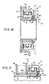
- a clutch release bearing intended to disengage a clutch mechanism (not shown) of a motor vehicle essentially consists of an operating member 10, a member of attack 11 and of a means of assembling these two members constituted here by an elastic washer 20.
- the operating member 10 comprises a sleeve 12 movable in the axial direction (arrow F) by sliding on any guide member such as a clutch trumpet under the action of a clutch control means, most often a fork (not shown) adapted to act on a flange or radial rim 13 formed for this purpose on said sleeve.
- the driving member 11 also has, in its usual way, a bearing for example a ball 14 with an outer non-rotating ring 15 and an inner rotating ring 16.
- the bearing comprises so usual for the proper maintenance of its balls a bearing cage (not detailed) and, for the retention of the lubrication grease, this is confined at the rear by a deflector 18 and at the front by a gasket sealing (not shown).
- the rear deflector 18 has a cylindrical central part 21 adapted to extend with a small clearance around the end part of the inner ring 16, an annular connection zone 22 perpendicular to the axis, a second cylindrical part 23 of larger diameter as the central part 21, and a peripheral part 24 adapted to fit into the bottom of the outer ring 15 of the bearing.
- This bottom is delimited by a rim 25 perpendicular to the axis and extending towards this axis up to a certain internal diameter D i substantially equal to the internal diameter of the internal ring 16.
- This inner ring also extends in an axial direction up to a certain distance d from the radial rim 25 of the outer ring.
- the operating member 10 which can advantageously be constituted by a molded part, has for its part, following its flange or radial rim 13, a shoulder 26 extending in an axial direction over a distance of less than l 'thickness e of the sheet constituting the ring 15 and established at a diameter less than the diameter D i of a certain clearance J predetermined for self-centering.
- This shoulder 26 is followed by a groove delimited by a bottom 27 and a frustoconical flank 28 forming support means which determines with the axial direction a certain half angle at the apex A.
- the frustoconical flank 28 moves away from the radial flange 13 at the same time as it moves away from the bottom 27 from which it comes.
- the axial dimension of the groove increases from its bottom 27 to its outlet at the level of the lip 29.
- This flank is delimited by a lip 29 of axial orientation with a diameter substantially equal to that of the shoulder 26, constituting the end zone of an engagement ramp 30 of frustoconical shape established with a half angle at the top A ′ significantly less than the angle A.
- a common cylindrical part of the sleeve with a certain diameter D o substantially equal to that of the bottom of the groove 27.
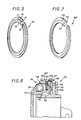
- the assembly means constituted according to the invention by the elastic washer 20, has at rest, as illustrated in FIG. 5, the shape of a torus interrupted by a slot extending over a small portion of the circumference .
- the diameter at rest of this washer is substantially equal to the diameter D o of the current part of the sleeve. In radial section, it has a profile delimited by two straight flanks 31, 32 placed in two planes perpendicular to the axis and separated from each other by a distance d 'slightly less than the axial distance d between the inner and outer rings of the bearing. , and more precisely between the rim 25 of the ring 15 and the adjacent terminal edge of the rotating ring 16.
- this profile On one of its faces comprising the profile 31 (which is located on the left in the drawings) this profile has the side radially inside a frustoconical face 33 and on the radially outside side a rebate 34. On its other face, there is simply provided on the radially inside side a slight chamfer 35.
- the washer 20 is put in place when the bearing constituting the driving member 11 is mounted in the position illustrated in FIG. 1: it can be seen that it finds its place with a certain radial clearance in the annular groove delimited by the radial rim 25 of the non-rotating ring 15, the end face of the rotating ring 16 and by the deflector 18. In the axial direction the clearance corresponds to the difference d - d ''.
- the attack member thus equipped engages without difficulty on the terminal part of the sleeve since the diameter D o of this part is, as we have seen, substantially equal to the diameter at rest of the washer 20; the chamfer 35 facilitates this engagement. The progression continues effortlessly until the start of ramp 30.
- the washer 20 engages by its frustoconical face 33 on the frustoconical flank 28 of the sleeve which has the effect of releasing the elastic energy accumulated by the expansion of the washer along the ramp 30.
- the washer tending to resume its rest configuration (at the diameter D o ) begins a descent of the frustoconical face 33 along the frustoconical flank 28: in axial direction the right flank 31 of the washer separates from the rotating ring 16, while its opposite right flank 32 will bear against the radial rim 25 of the non-rotating ring 15.
- This change of support takes place almost instantaneously in favor of the gentle play in the axial direction, the movement ending in the final position of FIG.
- the washer 20 bearing on the flank 28 due to its radial elasticity, exerts in the direction of the flange 13 an axial thrust, which is here directed towards the top of the cone defining this frustoconical flank.
- the top of the cone is directed in the direction of the axial thrust.
- the internal diameter D1 that reaches in this final position the washer 20 remains greater than its rest diameter D o by a quantity determined according to the invention so that, taking into account the elastic characteristics of the material constituting the washer, the moment of inertia from this, the axial component of the thrust exerted by means of the frustoconical flank 28 of the sleeve provides the required force for tightening the radial flange 25 against the flange 13 of said sleeve in order to allow the self-centering path that the bearing must be able to perform within the limits of the travel determined by the radial clearance J, while ensuring the maintenance of this self-centering.
- the radial rim 25 of the non-rotating ring 15 and the flange 13 of the sleeve 12 will also be called crowns of bearing.
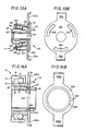
- Figures 6 and 7 illustrate the application of the invention to a clutch release bearing in which the leading nose is carried by the outer race ring.
- the deflector 118 here has a straight profile determining opposite the radial flange 125 directed towards the outside of the non-rotating ring 115 an annular housing of general shape rectangular for the elastic washer 120, the sectional shape of which is simplified consequently with a frustoconical face 133 situated here on the radially outer side.
- This washer will in fact cooperate in the present case with a support means arranged radially inwards of the operating member on a coaxial return 140 which is connected by a series of fastening tabs to the external periphery of the flange radial 113 of sleeve 112, rim which is shown here doubled with a wear plate 113A.
- the support means here again comprises a frustoconical flank 128 adapted to cooperate with the frustoconical face 133 of the washer 120, a lip 129 and an engagement ramp 130.
- the frustoconical flank 128 departs from the flange 113 at the same time as it moves away from the bottom 127 from which it comes.
- the elastic deformation undergone by the washer 120 is a narrowing of its outside diameter up to the minimum value determined by the lip 129 and that the desired tightening is effected by wedging of relaxation of the frustoconical face 133 along the corresponding tapered flank 128 of the support means.
- the washer 120 bearing on the sidewall 128 due to its radial elasticity, exerts in the direction of the flange 113 an axial thrust, which is here directed opposite the top of the cone defining this sidewall frustoconical. It will also be emphasized that the external periphery of the washer 120 is in the final position at a distance from the bottom of the groove so that the axial thrust is maintained.
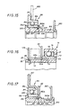
- the stop represented in FIG. 8 differs from the stops described above in that the groove defined by its bottom 27, its support flank 28, its lip 29 and the engagement ramp 30 is formed in the sleeve 12 towards the end of this sleeve axially opposite the flange 13.
- the radial elastic washer 20 thus comes to bear on an end edge 15A of the non-rotating ring 15, axially opposite the flange 25 directed towards the outside of this ring.
- the washer 20 is housed between the end edge 15A of the non-rotating ring 15, and the leading nose 17 of the rotating ring 16.
- the washer 20 carries, engaged in a peripheral groove, a seal 18 '' made of elastomer, with flexible lips which come into contact respectively with the internal face of the leading nose 17 and with the opposite face of the non-rotating ring 15.
- a seal 18 '' made of elastomer, with flexible lips which come into contact respectively with the internal face of the leading nose 17 and with the opposite face of the non-rotating ring 15.
- FIG. 9 represents a stop, where the rim 113 of the sleeve 112 is extended by a coaxial return 140 in analogy with the arrangement of FIG. 6.
- the washer 120 engaged in a groove made in the return 140, with a bottom 127, a frustoconical flank 128, a lip 129 and an engagement ramp 130, comes to take support on a wafer 115A of the non-rotating ring 115, opposite the flange 125 which forms the crown for bearing the non-rotating ring, extending towards the axis, pressing on the abutment crown of the sleeve 112 formed by the rim 113.
- the rotating ring 16 is interior.
- the flange 113 of the sleeve is doubled by an operating or wear plate 113A.
- the stop represented in FIG. 10 presents structural analogies with the stop represented in FIG. 8, in particular in that the elastic washer 20 bears on a edge 15A of the non-rotating ring 15 opposite the bearing crown 25, and in that the rotating ring 16 is external. But this stop is achieved with a very small axial size.
- the bearing 11 includes rings machined in rings.
- the rotating ring 16 has a leading nose 17 along a radial plane, and the non-rotating ring 15 is a ring of rectangular section, so that the bearing ring 25 is a straight edge.
- the stop comprises an operating or wear plate 63, taken between the rim 13 of the sleeve 12 and the bearing ring 25 of the non-rotating ring 15.
- the operating plate 63 comprises ears 63 a , for engagement with the clutch control means.
- the stop shown in Figure 11 has the same structure as that shown in Figure 10.
- the operating plate 63 of Figure 10 is replaced by a crown 65, 66 having a groove of rectangular section open radially outwards.
- This crown consists of a flat cheek 66, bearing on the edge 13 of the sleeve 12, and a cheek 65 integral with a tubular sheath 65 a which comes to rest on the flat cheek 66.
- This plate arrangement maneuver allows positive control of the movement of the stop 10, in traction and in thrust, by the declutching control means (not referenced) which engages in the groove.
- the stop shown in FIG. 12 also has a structure similar to that of FIGS. 10 and 11, with an outer rotating ring 16. But here the non-rotating ring 15 bears against the flange 13 located at the front of the sleeve 12 by an end edge 25 forming a bearing ring, and against an operating plate 63 by its opposite end edge 15A.
- the elastic washer 20 axially clamps the non-rotating ring 15 against the flange 13 by means of the operating plate 63.
- This operating plate 63 has a tubular sheath 63 b threaded on the sleeve 12, and ears 63 a for engaging the clutch control means.
- the groove in which the radial resilient washer 20 engages comprises, as before, a bottom 27, a frustoconical flank 28 remote from the flange 13 of the sleeve, a lip 29 and an engagement ramp 30 in a truncated cone to acute apex angle.
- FIGS. 13A and 13B represent a stop which has analogies with the stop of FIG. 9, with an inner rotating ring 116, and an elastic washer housing groove 120 formed in a return 140 from the rim 113 of the sleeve 112. But this stop comprises an operating plate 63 which is clamped between the rim 113 of the sleeve 112, and the end edge 125 forming a bearing ring for the non-rotating ring 115.
- the return 140 is divided into three tube segments which extend angularly over approximately 60 ° each, and also spaced about 60 ° apart.
- the drive plate 63 is generally disc-shaped, with ears 63 has thrust by the clutch control means.
- the maneuvering plate 63 has a central circular recess for the passage of the sleeve 112, and three recesses 63 c in the form of crown segments, extending over substantially 60 ° and spaced apart substantially 60 °, and provided to allow the return tube segments 140 to pass, including the lip 129 of the retaining groove of the elastic washer 120.
- FIGS. 14A and 14B show a simplified stop. Its structure is analogous to the stop of FIG. 12.
- the washer with radial elasticity 220 is arranged to form an operating plate. It has the shape of a ring, with a slot 221 intended to provide the necessary radial elasticity, and a frustoconical face 223, which comes to bear on the side 28 of the groove of the sleeve 12, to bring the clamping on the edge 15A of the non-rotating ring 15, supported by its other end edge 25 forming a bearing ring against the rim 13 of the sleeve 12.
- the washer 220 comprises, at 90 ° from the slot 221, ears 220 is engaged with the clutch control means.
- the stop consists of only three members, a bearing 11, a sleeve 12 and an operating plate 220.
- FIG. 15 represents a stop of the type called “pulled stop”, while the stops previously described were of the type called “pushed stop”.
- the references relating to the parts corresponding to an element of the stops according to FIG. 1 will be increased by 300 compared to those of this FIG. 1.
- pulled stop is meant a stop which works in traction and whose leading nose 317 is on the side opposite to that of the maneuvering plate 363 relative to the diaphragm the clutch 380.
- the stop comprises a sleeve 312 and a bearing 311 comprising a rotating ring 316 and, a non-rotating ring 315 and between the rings of the balls 314 (as mentioned above) the rotating ring 316 has a attack nose 317 machined in the rear face of a rim.
- the non-rotating ring 315 here interior, carries by its front edge 325 on a flange 313 forming crown rings.
- the edge 325 is held in abutment on the rim 313 by the thrust of a washer 20 with radial elasticity in tightening on the rear edge 315A of the non-rotating ring 315.
- the washer 20 is similar to the washers described with FIGS.
- the stop shown in FIG. 16 is very close to the stop shown in FIG. 11.
- the front edge 25 of the non-rotating ring 15 bears on an anterior flange 13 of the sleeve 12, set back from the leading nose 17 of the rotating ring 16
- On the rear edge 15A of the non-rotating ring 15 comes a cheek 65 secured to a tubular sheath 65 a which constitutes, with a flat cheek 170, an operating crown in which a disengaging control member engages, such as the fingers of a clutch release fork, for positive control of the stopper in both directions.
- the flat cheek 170 has a washer shape with radial elasticity. It is housed as a clamping support in a groove made in the sleeve 12 towards its rear end, and which comprises a bottom 27, a frustoconical flank 28, a lip 29 and an engagement ramp 30.
- the washer 170 does not, as according to the other figures, have a frustoconical face complementary to the support flank 28, and the internal bore of this washer 170 is cylindrical. The edges between the internal bore and the faces of the washer can be simply knocked down to avoid encrustation in the support flank 28.
- the stop shown in Figure 17 is a "pulled stop" similar to that of Figure 15, and has the same references.
- the nose 317 instead of being machined in the rotating ring 16 of the bearing, belongs to a stamped case crimped on this rotating ring.
- the operating member is a crown, consisting of an operating plate 316 and the elastic washer 20.
- the means of declutching control therefore acts in traction on the plate 316, and in thrust on the washer 20.
- the mounting of the stop comprises the positioning of the bearing 311 on the sleeve 312, the insertion of the washer 20 which goes up on the ramp engagement 330, passes over the cylindrical lip 329, to descend along the support flank 328 and tighten the non-rotating ring 315 on the flange 313.
- maneuvering plate 363 is threaded, with the cylindrical sleeve 363A on the shoulder of the sleeve provided for this purpose, and the sleeve 312 is then flared at the rear of the maneuvering plate 363, to crimp the latter.
- the external bore of the sleeve 363A comes flush with the external diameter of the sleeve 312, behind the engagement ramp 330.
- the tightening member with radial elasticity can be made of metal or plastic, and be made up in the most diverse forms; it is thus possible, instead of giving a ring a suitable elastic deformation capacity by a slot, constitute a ring with thinned periphery elements of appropriate shape between at least two cheeks distributed symmetrically around the axis where the support on the support flank 28 or 128 is preserved.
- the support of the bearing crowns of the non-rotating ring (15, 115) can be direct or indirect (as in FIGS. 10, 11 and 13A), and that the support of the elastic washer (20, 120) on this non-rotating ring can be direct, or indirect (as in Figures 12 and 16).
- the contact between the washer and the supporting flank takes place along the frustoconical face which at least one of these members has.
- the choice of the inclination of this face corresponding to the half angle at the top of the cone which defines the frustoconical face, determines the ratio of the axial thrust to the radial elastic return of the washer.
- the tightening of the device in the axial direction remains ensured by the residual elastic energy of the washer, which of course must not bear on the bottom of the groove. Furthermore, the axial size of the elastic washer, taking into account the axial clearances necessary for mounting, is reduced compared to the corresponding size of the axial elasticity washers.
Abstract
Description
L'invention se rapporte à une butée de débrayage, destinée à débrayer un mécanisme d'embrayage, cette butée comprenant un organe de manoeuvre comportant un manchon déplaçable axialement sous l'action d'un moyen de commande de débrayage, un organe d'attaque comprenant un roulement comportant une bague non tournante et une bague tournante entre lesquelles sont disposés des éléments roulants, un jeu radial étant ménagé entre la bague non tournante et l'organe de manoeuvre, un nez d'attaque, porté solidairement par la bague tournante du roulement, la bague non tournante du roulement et le manchon présentant respectivement des couronnes de portée ou rebords perpendiculaires à l'axe, ces couronnes ou rebords étant sollicités en appui l'un vers l'autre par une rondelle élastique portant sur des moyens d'appui de l'organe de manoeuvre d'un côté, et poussant la bague non tournante de l'autre de manière à assurer un serrage axial afin d'une part d'assembler le roulement et l'organe de manoeuvre et d'autre part permettre un autocentrage maintenu de la butée de débrayage par rapport à l'organe de manoeuvre.The invention relates to a declutching stop, intended to disengage a clutch mechanism, this stop comprising an operating member comprising a sleeve movable axially under the action of a declutching control means, a driving member. comprising a bearing comprising a non-rotating ring and a rotating ring between which are arranged rolling elements, a radial clearance being formed between the non-rotating ring and the operating member, a leading nose, carried integrally by the rotating ring of the bearing, the non-rotating ring of the bearing and the sleeve respectively having bearing rings or flanges perpendicular to the axis, these rings or flanges being urged to bear towards each other by an elastic washer bearing on means of support of the operating member on one side, and pushing the non-rotating ring on the other so as to ensure axial tightening in order on the one hand to assemble the bearing and the operating member and on the other hand allow a maintained self-centering of the clutch release bearing relative to the operating member.
Dans leur conception générale de telles butées, dites autocentreuses à autocentrage maintenu en raison des possibilités de jeu radial entre le roulement qui adopte l'axe de rotation du mécanisme d'embrayage et l'organe de manoeuvre maintenu sur son axe propre, sont connues de longue date par exemple par le document de brevet FR-A 1.467.843 rendu public le 3 Février 1967. Les perfectionnements qui y sont apportés visent la simplification et l'allègement de la structure et du montage, et la réduction de l'encombrement avec pour corollaire le dégagement des parties fonctionnement actives, c'est-à-dire le nez d'attaque du mécanisme d'embrayage et la face du rebord de l'organe de manoeuvre sur laquelle porte le moyen de commande de débrayage.In their general design, such stops, called self-centering self-centering maintained due to the possibilities of radial clearance between the bearing which adopts the axis of rotation of the clutch mechanism and the operating member maintained on its own axis, are known from for a long time for example by the patent document FR-A 1,467,843 made public on February 3, 1967. The improvements which are brought there aim the simplification and the lightening of the structure and the assembly, and the reduction of congestion with as a corollary, the release of the active operating parts, that is to say the nose of the clutch mechanism and the face of the flange the operating member to which the clutch control means bears.
Comme l'autocentrage maintenu implique, outre bien entendu un jeu radial omnidirectionnel entre le roulement et l'organe de manoeuvre, persistant après le montage de la butée, un serrage avec une force réglée du rebord de la bague non tournante du roulement contre le rebord de l'organe de manoeuvre, on a mis en place des moyens élastiques de serrage susceptibles de prendre appui sur l'organe de manoeuvre d'une part, et sur un rebord de la bague non tournante d'autre part.As the maintained self-centering implies, in addition of course an omnidirectional radial clearance between the bearing and the operating member, persistent after the mounting of the stop, a tightening with a regulated force of the edge of the non-rotating ring of the bearing against the edge of the operating member, elastic clamping means have been put in place capable of bearing on the operating member on the one hand, and on a flange of the non-rotating ring on the other hand.
Couramment ces moyens élastiques de serrage sont constitués d'une rondelle élastique préformée en extension axiale, à forme tronconique ou ondulée, en appui sur un des organes, rebord ou manchon, et munie de pattes d'accrochage susceptibles de venir s'enclipser sur l'autre organe, par une déformation élastique provoquée à l'encontre de la déformation originaire.Commonly these elastic clamping means consist of an elastic washer preformed in axial extension, in frustoconical or wavy shape, bearing on one of the members, flange or sleeve, and provided with latching tabs capable of being snapped onto the 'other organ, by an elastic deformation caused against the original deformation.
Cette rondelle élastique vient se placer entre le roulement et le rebord de l'organe de manoeuvre, dans une région où la place est limitée en raison de la recherche de compacité, et très peu accessible à des outils de poussée capables de provoquer la déformation élastique à l'encontre de la déformation originaire.This elastic washer is placed between the bearing and the edge of the operating member, in a region where space is limited due to the search for compactness, and very inaccessible to pushing tools capable of causing elastic deformation. against the original deformation.
Les documents de brevet FR-A-2.465.119 et 2.465.120 décrivent des rondelles à forme conique qui sont placées du côté du rebord de l'organe de manoeuvre opposé à celui où s'appuie le rebord de bague non tournante, ce rebord formant plaque d'appui étant susceptible de coulisser axialement sur le manchon, tandis que ce dernier porte une saillie annulaire contre laquelle porte le rebord de bague non tournante. Cette disposition résout les problèmes d'encombrement entre roulement et rebord d'organe de manoeuvre, au prix d'un allongement du manchon, et d'un risque d'interférence avec le moyen de commande de débrayage.Patent documents FR-A-2,465,119 and 2,465,120 describe washers with conical shape which are placed on the side of the edge of the operating member opposite to that on which the edge of the non-rotating ring rests, this edge forming a support plate capable of sliding axially on the sleeve, while the latter carries an annular projection against which the non-rotating ring flange bears. This arrangement solves the problems of space between the bearing and the flange of the operating member, at the cost of lengthening the sleeve, and of a risk of interference with the clutch control means.
Dans le document de brevet FR-A-2.544.429 est décrite une disposition selon laquelle une rondelle élastique d'accrochage du type dit à retournement, à configuration bistable, agit entre le manchon et le rebord de la bague non tournante. A la mise en place du roulement sur le manchon, la rondelle est déformée jusqu'au delà de sa configuration de retournement.In patent document FR-A-2,544,429 is described an arrangement according to which an elastic attachment washer of the so-called inversion type, with a bistable configuration, acts between the sleeve and the rim of the non-rotating ring. When the bearing is placed on the sleeve, the washer is deformed to beyond its overturning configuration.
Dans le document de brevet FR-A-2.547.002, est décrite une rondelle élastique d'accrochage à configuration conique, munie de pattes d'accrochage constituant une douille pour l'enfilage sur le manchon, un outil tubulaire inséré dans le jeu entre roulement et manchon poussant en bout les pattes jusqu'à ce qu'elles viennent s'encliqueter derrière un jonc ménagé sur le manchon.In patent document FR-A-2,547,002, an elastic hooking washer with a conical configuration is described, provided with hooking tabs constituting a socket for threading on the sleeve, a tubular tool inserted in the game between bearing and sleeve pushing the tabs at the end until they snap behind a rod formed on the sleeve.
Dans la demande de brevet français 84 02 584, déposée le 21 Février 1984, est décrite une rondelle élastique avec des pattes formant en coopération avec une saillie annulaire interrompue sur le manchon, un accrochage du genre dit à baïonnette, avec des rampes d'entrée telles que la précontrainte d'élasticité axiale est obtenue par la rotation de la rondelle précédant l'accrochage à baïonnette.In French patent application 84 02 584, filed on February 21, 1984, is described an elastic washer with lugs forming in cooperation with an annular projection interrupted on the sleeve, a hooking of the so-called bayonet type, with entry ramps such that the axial elastic preload is obtained by the rotation of the washer preceding the bayonet attachment.
L'élasticité axiale de la rondelle résulte de la déformation originaire en extension axiale, soit en forme tronconique, soit en forme ondulée.The axial elasticity of the washer results from the original deformation in axial extension, either in frustoconical shape, or in wavy shape.
Toutes les dispositions antérieures ont pour inconvénient inhérent que l'encombrement axial de la rondelle élastique est déterminé par l'extension axiale d'élasticité au moins en position précontrainte. Sauf lorsque, par des dispositions qui compliquent la structure de butée, la rondelle élastique est reportée de l'autre côté du rebord d'appui du moyen de commande de débrayage (FR-A-2.465.119 ; FR-A-2.465.120) l'encombrement axial de la rondelle se situe entre l'extrémité de la bague tournante et le rebord de la bague non tournante du roulement, dont la longueur se trouve ainsi augmentée. Par ailleurs le montage du roulement sur l'organe de manoeuvre exige l'intervention d'un outil qui accède à la rondelle soit par le jeu entre roulement et organe de manoeuvre, soit à travers des orifices ménagés dans le rebord de l'organe de manoeuvre. Enfin accessoirement la mise en forme des rondelles élastiques, et le réglage de leur élasticité nécessitent des outillages de mise en forme complexes et des traitements thermiques bien contrôlés.All the previous arrangements have the inherent drawback that the axial size of the elastic washer is determined by the axial extension of elasticity at least in the prestressed position. Except when, by provisions which complicate the abutment structure, the elastic washer is transferred to the other side of the bearing flange of the clutch control means (FR-A-2.465.119; FR-A-2.465.120 ) the axial size of the washer is located between the end of the rotating ring and the edge of the non-rotating ring of the bearing, the length of which is thus increased. Furthermore, the mounting of the bearing on the operating member requires the intervention of a tool which accesses the washer either by the clearance between the bearing and the operating member, or through holes in the edge of the operating member. Finally incidentally the shaping of the elastic washers, and the adjustment of their elasticity require complex shaping tools and well-controlled heat treatments.
L'invention a pour objectif une butée de débrayage du genre qui vient d'être décrit, où la rondelle élastique utilise un encombrement axial sensiblement limité à son épaisseur, et dont l'assemblage est très simplifié.The object of the invention is to provide a declutching stop of the kind which has just been described, in which the elastic washer uses an axial size substantially limited to its thickness, and the assembly of which is very simplified.
A cet effet l'invention propose une butée de débrayage, destinée à débrayer un mécanisme d'embrayage, cette butée comprenant un organe de manoeuvre comportant un manchon déplaçable axialement sous l'action d'un moyen de commande de débrayage, un organe d'attaque comprenant un roulement comportant une bague non tournante et une bague tournante entre lesquelles sont disposés des éléments roulants, un nez d'attaque porté solidairement par la bague tournante du roulement, la bague non tournante et le manchon présentant respectivement des couronnes de portée perpendiculaires à l'axe, ces couronnes étant sollicitées en appui l'une vers l'autre par une rondelle élastique portant sur des moyens d'appui de l'organe de manoeuvre d'un côté, et poussant la bague non tournante de l'autre de manière à assurer un serrage axial afin, d'une part, d'assembler le roulement et l'organe de manoeuvre et, d'autre part, de permettre un autocentrage maintenu de la butée de débrayage par rapport au manchon, caractérisée en ce que lesdits moyens d'appui de l'organe de manoeuvre contre lesquels porte la rondelle élastique comportent une gorge annulaire ménagée dans l'organe de manoeuvre avec un fond entre deux flancs dont le plus éloigné de la couronne de portée dudit organe de manoeuvre, dit flanc d'appui, s'étend depuis le fond jusqu'à une lèvre tandis que la rondelle élastique est un organe à élasticité radiale avec un profil adapté à coopérer avec celui de la gorge, l'un au moins dudit flanc d'appui et de la rondelle présentant une face tronconique, ladite rondelle ayant une capacité de déformation radiale suffisante pour franchir la lèvre de la gorge de telle sorte que le rappel élastique radial de la rondelle coopérant avec ledit flanc d'appui provoque le serrage axial de la couronne de portée de bague non tournante et de la couronne de portée du manchon sans que la rondelle porte sur le fond de la gorge.To this end, the invention provides a declutching stop, intended to disengage a clutch mechanism, this stop comprising an actuating member comprising a sleeve movable axially under the action of a declutching control means, a member of etching comprising a bearing comprising a non-rotating ring and a rotating ring between which are arranged rolling elements, a leading nose carried integrally by the rotating ring of the bearing, the non-rotating ring and the sleeve respectively having crowns of bearing perpendicular to the axis, these crowns being urged to bear towards one another by an elastic washer bearing on support means of the operating member on one side, and pushing the non-rotating ring on the other from so as to ensure an axial tightening in order, on the one hand, to assemble the bearing and the actuating member and, on the other hand, to allow a self-centering maintained of the release bearing relative to the sleeve, because actuated in that said support means of the operating member against which the elastic washer bears comprise an annular groove formed in the operating member with a bottom between two sides, the most distant from the crown of bearing of said member maneuver, said support flank, extends from the bottom to a lip while the elastic washer is a member with radial elasticity with a profile adapted to cooperate with that of the groove, at least one of said flank d support and washer having a frustoconical face, said washer having a radial deformation capacity sufficient to cross the lip of the groove so that the radial elastic return of the washer cooperating with said bearing flank causes the axial tightening of the non-rotating ring bearing crown and the sleeve bearing crown without the washer is on the back of the throat.
On conçoit sans peine que, la mise en place de la rondelle, et son action de poussée axiale résultant uniquement de déformations radiales, l'encombrement axial de la rondelle est à peine supérieur à son épaisseur axiale propre. En outre, la déformation radiale nécessaire pour franchir la lèvre de gorge ne s'accompagnant pas de déformation axiale, la rondelle peut être poussée, pour l'assemblage, par la tranche terminale de la bague tournante, le retour élastique radial de la rondelle dès que la lèvre est franchie provoquant, à la fois le serrage axial du rebord de bague non tournante contre le rebord de l'organe de manoeuvre, et la prise de jeu juste indispensable entre la tranche terminale de bague tournante du roulement et la rondelle élastique.It is easily understood that, the installation of the washer, and its axial thrust action resulting solely from radial deformations, the axial size of the washer is barely greater than its own axial thickness. In addition, the radial deformation necessary to cross the groove lip being not accompanied by axial deformation, the washer can be pushed, for assembly, by the end edge of the rotating ring, the radial elastic return of the washer from that the lip is crossed, causing both the axial tightening of the rim of the non-rotating ring against the rim of the operating member, and the just essential clearance between the end portion of the rotating ring of the bearing and the elastic washer.
Il est sans doute surprenant que la solution proposée par la Demanderesse au problème que pose l'assemblage des butées autocentreuses, problème aussi ancien que les butées autocentreuses elles-mêmes, n'ait pas vu le jour plus tôt. On peut se demander toutefois si les constructeurs de butées autocentreuses n'ont pas envisagé la question sous le seul angle de la poussée élastique axiale résultant d'une déformation élastique dans le sens de la poussée recherchée.It is undoubtedly surprising that the solution proposed by the Applicant to the problem posed by the assembly of the self-centering stops, a problem as old as the self-centering stops themselves, did not emerge earlier. One may wonder, however, whether the manufacturers of self-centering stops did not consider the question solely from the angle of the axial elastic thrust resulting from elastic deformation in the direction of the desired thrust.
De préférence, l'organe de manoeuvre comporte une rampe tronconique à angle au sommet aigu qui s'achève à la lèvre de la gorge. Cette rampe, relativement douce, facilite la déformation radiale de la rondelle élastique pour le franchissement de la lèvre.Preferably, the operating member comprises a frustoconical ramp at an angle with an acute apex which ends at the lip of the throat. This relatively soft ramp facilitates the radial deformation of the elastic washer for crossing the lip.
Dans une version de l'invention, la gorge est pratiquée dans le manchon.In one version of the invention, the groove is made in the sleeve.
En variante, l'organe de manoeuvre comporte à la périphérie extérieur de son rebord un retour coaxial au manchon, et la gorge est pratiquée dans ce retour.As a variant, the operating member comprises at the outer periphery of its rim a coaxial return to the sleeve, and the throat is practiced in this return.
En disposition préférée la rondelle est en forme de bague fendue et présente une largeur radiale supérieure à son épaisseur axiale, en sorte de posséder un rappel élastique radial relativement élevé avec un encombrement axial réduit.In preferred arrangement, the washer is in the form of a split ring and has a radial width greater than its axial thickness, so as to have a relatively high radial elastic return with a reduced axial bulk.
De préférence, le flanc tronconique de la gorge présente un angle au sommet supérieur à 90°C. Ceci permet de disposer d'une poussée axiale supérieure au rappel radial.Preferably, the frustoconical flank of the groove has an apex angle greater than 90 ° C. This provides an axial thrust greater than the radial return.
Par ailleurs, la bague élastique peut porter sur une tranche de la bague non tournante opposée axialement à la couronne de portée. Dans une disposition particulière de l'invention, la butée comporte une plaque de manoeuvre sur laquelle porte le moyen de commande de débrayage, et cette portée de manoeuvre est pincée entre les couronnes de portée de la bague non tournante et de l'organe de manoeuvre.Furthermore, the elastic ring can bear on a edge of the non-rotating ring axially opposite the bearing ring. In a particular arrangement of the invention, the stop comprises an operating plate on which bears the declutching control means, and this operating range is pinched between the bearing rings of the non-rotating ring and of the operating member .
Les caractéristiques et avantages de l'invention ressortiront d'ailleurs de la description qui va suivre à titre d'exemple, en référence aux dessins annexés dans lesquels:
- la figure 1 est une vue en coupe radiale d'une butée de débrayage selon l'invention en cours de montage ;
- les figures 2 et 3 sont des vues semblables montrant deux étapes suivantes du montage ;
- la figure 4 est une vue encore semblable montrant la butée en position montée ;
- la figure 5 est une vue en perspective de la rondelle élastique mise en oeuvre dans la butée des figures 1 à 4 ;
- la figure 6 est une vue en coupe radiale d'une autre forme de réalisation de butée ;
- la figure 7 est une vue en perspective de la rondelle élastique de la butée de la figure 6 ;
- les figures 8 et 9 représentent des variantes de l'invention ;
- la figure 10 représente encore une variante de l'invention ;
- la figure 11 représente un aménagement de la butée représentée à la figure 10 ;
- la figure 12 représente une autre variante de l'invention ;
- les figures 13A et 13B représentent encore une autre variante de l'invention ;
- les figures 14A et 14B représentent une variante simplifiée de l'invention ;
- la figure 15 représente une variante de l'invention pour butée tirée ;
- la figure 16 représente une variante de l'invention analogue à celle de la figure 11 ;
- la figure 17 représente une variante de l'invention analogue à celle de la figure 11, mais pour butée tirée.
- Figure 1 is a radial sectional view of a clutch release bearing according to the invention during assembly;
- Figures 2 and 3 are similar views showing two following stages of assembly;
- Figure 4 is a still similar view showing the stopper in the mounted position;
- Figure 5 is a perspective view of the elastic washer used in the stop of Figures 1 to 4;
- Figure 6 is a radial sectional view of another embodiment of the stopper;
- Figure 7 is a perspective view of the elastic washer of the stopper of Figure 6;
- Figures 8 and 9 show variants of the invention;
- FIG. 10 also represents a variant of the invention;
- Figure 11 shows an arrangement of the stop shown in Figure 10;
- Figure 12 shows another variant of the invention;
- Figures 13A and 13B show yet another variant of the invention;
- Figures 14A and 14B show a simplified variant of the invention;
- FIG. 15 shows a variant of the invention for a pulled stop;
- Figure 16 shows a variant of the invention similar to that of Figure 11;
- Figure 17 shows a variant of the invention similar to that of Figure 11, but for pulled stop.
Suivant la forme de réalisation choisie et représentée aux figures 1 à 5, une butée de débrayage destinée à débrayer un mécanisme d'embrayage (non représenté) de véhicule automobile se compose essentiellement d'un organe de manoeuvre 10, d'un organe d'attaque 11 et d'un moyen d'assemblage de ces deux organes constitués ici par une rondelle élastique 20.According to the embodiment chosen and shown in Figures 1 to 5, a clutch release bearing intended to disengage a clutch mechanism (not shown) of a motor vehicle essentially consists of an operating
L'organe de manoeuvre 10 comporte un manchon 12 déplaçable en sens axial (flèche F) par coulissement sur un quelconque organe de guidage tel qu'une trompette d'embrayage sous l'action d'un moyen de commande de débrayage, le plus souvent une fourchette (non représentée) adaptée à agir sur un flasque ou rebord radial 13 ménagé à cet effet sur ledit manchon.The operating
L'organe d'attaque 11 comporte de son côté, de manière également usuelle, un roulement par exemple à billes 14 avec une bague extérieure non tournante 15 et une bague intérieure tournante 16.The driving
Ces deux bagues sont de manière connue en soi constituées ici l'une et l'autre en tôle emboutie, la bague ici intérieure 16 présentant un nez 17 d'attaque adapté à agir sur le dispositif débrayeur d'un embrayage non représenté tel que, les extrémités des doigts d'un diaphragme d'embrayage. Le roulement comporte de manière usuelle pour le maintien convenable de ses billes une cage de roulement (non détaillée) et, pour la retenue de la graisse de lubrification, celle-ci est confinée à l'arrière par un déflecteur 18 et à l'avant par un joint d'étanchéité (non représenté). Le déflecteur postérieur 18 comporte une partie centrale cylindrique 21 adaptée à s'étendre avec un faible jeu autour de la partie terminale de la bague interne 16, une zone annulaire de raccordement 22 perpendiculaire à l'axe, une seconde partie cylindrique 23 de plus grand diamètre que la partie centrale 21, et une partie périphérique 24 adaptée à s'emboîter dans le fond de la bague extérieure 15 du roulement. Ce fond est délimité par un rebord 25 perpendiculaire à l'axe et s'étendant vers cet axe jusqu'à un certain diamètre intérieur Di sensiblement égal au diamètre intérieur de la bague intérieure 16.These two rings are, in a manner known per se, made here both of stamped sheet metal, the ring here interior 16 having a
Cette bague intérieure s'étend par ailleurs en sens axial jusqu'à une certaine distance d du rebord radial 25 de la bague extérieure.This inner ring also extends in an axial direction up to a certain distance d from the
L'organe de manoeuvre 10, qui peut avantageusement être constitué par une pièce moulée, présente de son côté, à la suite de son flasque ou rebord radial 13, un épaulement 26 s'étendant en sens axial sur une distance d' inférieure à l'épaisseur e de la tôle constituant la bague 15 et établi à un diamètre inférieur au diamètre Di d'un certain jeu J prédeterminé pour l'autocentrage. Cet épaulement 26 est suivi d'une gorge délimitée par un fond 27 et un flanc tronconique 28 formant moyen d'appui qui détermine avec la direction axiale un certain demi angle au sommet A.The operating
En fait, le flanc tronconique 28 s'écarte du flasque radial 13 en même temps qu'il s'éloigne du fond 27 dont il est issu. Autrement dit la dimension axiale de la gorge augmente de son fond 27 à son débouché au niveau de la lèvre 29.In fact, the
Ce flanc est délimité par une lèvre 29 d'orientation axiale de diamètre sensiblement égal à celui de l'épaulement 26, constituant la zone d'aboutissement d'une rampe d'engagement 30 de forme tronconique établi avec un demi angle au sommet A' nettement inférieure à l'angle A. Au bout de cette rampe se trouve une partie cylindrique courante du manchon avec un certain diamètre Do sensiblement égal à celui du fond de gorge 27.This flank is delimited by a
Enfin, le moyen d'assemblage, constitué selon l'invention par la rondelle élastique 20, présente au repos, comme illustré à la figure 5, la forme d'un tore interrompu par une fente s'étendant sur une faible portion de la circonférence. Le diamètre au repos de cette rondelle est sensiblement égal au diamètre Do de la partie courante du manchon. En section radiale elle présente un profil délimité par deux flancs droits 31, 32 se plaçant dans deux plans perpendiculaires à l'axe et séparés entre eux d'une distance d'' légèrement inférieure à la distance axiale d entre bagues intérieure et extérieure du roulement, et plus précisément entre le rebord 25 de la bague 15 et la tranche terminale voisine de la bague tournante 16. Sur l'une de ses faces comprenant le profil 31 (qui est située à gauche sur les dessins) ce profil présente du côté radialement intérieur une face tronconique 33 et du côté radialement extérieur une feuillure 34. Sur son autre face il est simplement prévu du côté radialement intérieur un léger chanfrein 35.Finally, the assembly means, constituted according to the invention by the
On va décrire maintenant le montage et le fonctionnement de la butée de débrayage ainsi constituée.We will now describe the assembly and operation of the clutch release bearing thus formed.
La rondelle 20 est mise en place au montage du roulement constituant l'organe d'attaque 11 dans la position illustrée à la figure 1 : on voit qu'elle trouve sa place avec un certain jeu radial dans la gorge annulaire délimitée par le rebord radial 25 de la bague non tournante 15, la face terminale de la bague tournante 16 et par le déflecteur 18. En sens axial le jeu correspond à l'écart d-d''. L'organe d'attaque ainsi équipé s'engage sans difficulté sur la partie terminale du manchon puisque le diamètre Do de cette partie est, on l'a vu, sensiblement égal au diamètre au repos de la rondelle 20 ; le chanfrein 35 facilite cet engagement. La progression se poursuit sans effort jusqu'au début de la rampe 30.The
La progression le long de cette rampe va impliquer la mise en oeuvre d'une poussée axiale d'intensité croissante, puisque la rondelle se trouve forcée à s'ouvrir progressivement jusqu'à un maximum correspondant à la position de la figure 2 où la rondelle 20 est amenée à chevaucher la lèvre 29. Il y a lieu de noter que dans cette position le jeu radial est pratiquement absorbé autour de la rondelle ; au jeu axial près la section transversale de la rondelle occupe ici la quasi totalité de la place disponible à l'intérieur du déflecteur 18. La poussée axiale était et demeure pour l'instant exercée sur la rondelle 20 par la face terminale de la bague tournante 16.The progression along this ramp will imply the implementation of an axial thrust of increasing intensity, since the washer is forced to open gradually until a maximum corresponding to the position of Figure 2 where the
Dès que se trouve franchie cependant la lèvre 29, comme le montre la figure 3, la rondelle 20 s'engage par sa face tronconique 33 sur le flanc tronconique 28 du manchon ce qui a pour effet de libérer l'énergie élastique accumulée par l'expansion de la rondelle le long de la rampe 30. La rondelle tendant à reprendre sa configuration de repos (au diamètre Do) entame une descente de la face tronconique 33 le long du flanc tronconique 28 : en sens axial le flanc droit 31 de la rondelle se sépare de la bague tournante 16, tandis que son flanc droit opposé 32 va prendre appui contre le rebord radial 25 de la bague non tournante 15. Ce changement d'appui s'opère de façon quasi-instantanée à la faveur du jeu ménagé en sens axial, le mouvement s'achevant à la position finale de la figure 4 où la rondelle 20 se trouve resserrée à un certain diamètre interne D1 et où avec effet de coincement entre les faces tronconiques coopérantes 33 et 28 le rebord radial 25 de la bague non tournante est plaqué contre le flasque 13 du manchon.As soon as the
On remarquera que la rondelle 20, prenant appui sur le flanc 28 en raison de son élasticité radiale, exerce en direction du flasque 13 une poussée axiale, qui est ici dirigée vers le sommet du cône définissant ce flanc tronconique. Il en résulte que le sommet du cône est dirigé dans le sens de la poussée axiale.It will be noted that the
Il importe de noter que le diamètre interne D1 qu'atteint dans cette position finale la rondelle 20 demeure supérieur à son diamètre de repos Do d'une quantité déterminée selon l'invention de telle sorte que, compte tenu des caractéristiques élastiques du matériau constitutif de la rondelle, du moment d'inertie de celle-ci, la composante axiale de la poussée exercée par l'intermédiaire du flanc tronconique 28 du manchon assure la force requise de serrage du rebord radial 25 contre le flasque 13 dudit manchon afin de permettre le cheminement d'autocentrage que le roulement doit pouvoir effectuer dans les limites du débattement déterminé par le jeu radial J, tout en assurant le maintien de cet autocentrage.It is important to note that the internal diameter D1 that reaches in this final position the
En raison de leurs fonctions, le rebord radial 25 de la bague non tournante 15 et le flasque 13 du manchon 12 seront dits également couronnes de portée.Because of their functions, the
Les figures 6 et 7 illustrent l'application de l'invention à une butée de débrayage dans laquelle le nez d'attaque est porté par la bague de roulement extérieure. On a repris ici les numéros de références déjà utilisés dans le cas précédent majorés de 100. Le déflecteur 118 présente ici un profil droit déterminant en regard du rebord radial 125 dirigé vers l'extérieur de la bague non tournante 115 un logement annulaire de forme générale rectangulaire pour la rondelle élastique 120 dont la forme de section est simplifiée en conséquence avec une face tronconique 133 située ici du côté radialement extérieur. Cette rondelle va coopérer en effet dans le cas présent avec un moyen d'appui ménagé radialement vers l'intérieur de l'organe de manoeuvre sur un retour coaxial 140 qui est relié par une série de pattes d'attache à la périphérie externe du rebord radial 113 du manchon 112, rebord qui est montré doublé ici d'une plaque d'usure 113A. Le moyen d'appui comporte ici encore un flanc tronconique 128 adapté à coopérer avec la face tronconique 133 de la rondelle 120, une lèvre 129 et une rampe d'engagement 130. Comme dans les figures précédentes, le flanc tronconique 128 s'écarte du flasque 113 en même temps qu'il s'éloigne du fond 127 dont il est issu.Figures 6 and 7 illustrate the application of the invention to a clutch release bearing in which the leading nose is carried by the outer race ring. We have used here the reference numbers already used in the previous case increased by 100. The
On aura compris que dans le cas présent la déformation élastique subie par la rondelle 120 est un rétrécissement de son diamètre extérieur jusqu'à la valeur minimale déterminée par la lèvre 129 et que le serrage recherché s'opère par coincement de détente de la face tronconique 133 le long du flanc tronconique correspondant 128 du moyen d'appui.It will be understood that in the present case the elastic deformation undergone by the
On remarquera que, dans cette disposition, la rondelle 120, prenant appui sur le flanc 128 en raison de son élasticité radiale, exerce en direction du flasque 113 une poussée axiale, qui est ici dirigée à l'opposé du sommet du cône définissant ce flanc tronconique. On soulignera par ailleurs que la périphérie externe de la rondelle 120 est en position finale à distance du fond de la gorge pour que la poussée axiale soit maintenue.It will be noted that, in this arrangement, the
La butée représentée à la figure 8 diffère des butées décrites précédemment en ce que la gorge définie par son fond 27, son flanc d'appui 28, sa lèvre 29 et la rampe d'engagement 30 est pratiquée dans le manchon 12 vers l'extrémité de ce manchon axialement opposée au rebord 13. La rondelle à élasticité radiale 20 vient ainsi prendre appui sur une tranche d'extrémité 15A de la bague non tournante 15, opposée axialement au rebord 25 dirigé vers l'extérieur de cette bague. La rondelle 20 est logée entre la tranche d'extrémité 15A de la bague non tournante 15, et le nez d'attaque 17 de la bague tournante 16. A sa périphérie extérieure la rondelle 20 porte, engagé dans une rainure périphérique, un joint 18' en élastomère, avec des lèvres souples qui viennent au contact respectivement de la face interne du nez d'attaque 17 et de la face en regard de la bague non tournante 15. On notera que dans cette disposition la bague tournante 16 est extérieure et la gorge pratiquée dans le manchon 12. Le rebord 13 du manchon 12 est doublé d'une plaque de manoeuvre 13A formant plaque d'usure. Le moyen de commande de débrayage vient prendre appui sur la plaque de manoeuvre 13A.The stop represented in FIG. 8 differs from the stops described above in that the groove defined by its bottom 27, its
On rappelle la règle énoncée à l'occasion des figures 1 à 5. La rondelle 20 étant en serrage élastique, le sommet du cône définissant la rampe tronconique est dirigé dans le sens de la poussée axiale.We recall the rule stated on the occasion of the figures 1 to 5. The
La figure 9 représente une butée, où le rebord 113 du manchon 112 se prolonge par un retour coaxial 140 en analogie avec la disposition de la figure 6.FIG. 9 represents a stop, where the
Mais, comme dans la représentation de la figure 8 la rondelle 120, engagée dans une gorge pratiquée dans le retour 140, avec un fond 127, un flanc d'appui tronconique 128, une lèvre 129 et une rampe d'engagement 130, vient prendre appui sur une tranche 115A de la bague non tournante 115, à l'opposé du rebord 125 qui forme couronne de portée de la bague non tournante, en s'étendant vers l'axe, en appui sur la couronne de butée du manchon 112 formée par le rebord 113. Dans cette disposition la bague tournante 16 est intérieure. Par ailleurs, le rebord 113 du manchon est doublé par une plaque de manoeuvre ou d'usure 113A.But, as in the representation of FIG. 8, the
La butée représentée figure 10 présente des analogies de structure avec la butée représentée figure 8 notamment en ce que la rondelle élastique 20 porte sur une tranche 15A de la bague non tournante 15 à l'opposé de la couronne de portée 25, et en ce que la bague tournante 16 est extérieure. Mais cette butée est réalisée avec un encombrement axial très réduit.The stop represented in FIG. 10 presents structural analogies with the stop represented in FIG. 8, in particular in that the
Dans ce but le roulement 11 comporte des bagues usinées dans des anneaux. La bague tournante 16 comporte un nez d'attaque 17 suivant un plan radial, et la bague non tournante 15 est un anneau à section rectangulaire, de sorte que la couronne de portée 25 est une tranche droite. La butée comporte une plaque de manoeuvre ou d'usure 63, prise entre le rebord 13 du manchon 12 et la couronne de portée 25 de la bague non tournante 15. La plaque de manoeuvre 63 comporte des oreilles 63a, pour l'engagement avec le moyen de commande de débrayage.For this purpose, the
La butée représentée figure 11 comporte la même structure que celle qui est représentée figure 10. Toutefois la plaque de manoeuvre 63 de la figure 10 est remplacée par une couronne 65,66 présentant une gorge à section rectangulaire ouverte radialement vers l'extérieur. Cette couronne est constitutée d'une joue plate 66, en appui sur le bord 13 du manchon 12, et d'une joue 65 solidaire d'un fourreau tubulaire 65a qui vient s'appuyer sur la joue plate 66. Cette disposition de plaque de manoeuvre permet la commande positive du mouvement de la butée 10, en traction et en poussée, par le moyen de commande de débrayage (non référencé) qui s'engage dans la gorge.The stop shown in Figure 11 has the same structure as that shown in Figure 10. However the operating
La butée représentée figure 12 présente encore une structure analogue à celles des figures 10 et 11, avec une bague tournante 16 extérieure. Mais ici la bague non tournante 15 porte contre le rebord 13 situé à l'avant du manchon 12 par une tranche d'extrémité 25 formant couronne de portée, et contre une plaque de manoeuvre 63 par sa tranche d'extrémité opposée 15A. La rondelle élastique 20 vient serrer axialement la bague non tournante 15 contre le rebord 13 par l'intermédiaire de la plaque de manoeuvre 63. Cette plaque de manoeuvre 63 présente un fourreau tubulaire 63b enfilé sur le manchon 12, et des oreilles 63a pour l'engagement du moyen de commande de débrayage. La gorge où s'engage la rondelle à élasticité radiale 20 comporte, comme précédemment, un fond 27, un flanc d'appui tronconique 28 éloigné du rebord 13 de manchon, une lèvre 29 et une rampe d'engagement 30 en tronc de cône à angle au sommet aigu.The stop shown in FIG. 12 also has a structure similar to that of FIGS. 10 and 11, with an outer
Les figures 13A et 13B représentent une butée qui comporte des analogies avec la butée de la figure 9, avec une bague tournante 116 intérieure, et une gorge de logement de rondelle élastique 120 ménagée dans un retour 140 du rebord 113 du manchon 112. Mais cette butée comporte une plaque de manoeuvre 63 qui est serrée entre le rebord 113 du manchon 112, et la tranche terminale 125 formant couronne de portée pour la bague non tournante 115.FIGS. 13A and 13B represent a stop which has analogies with the stop of FIG. 9, with an inner
Aussi le retour 140 est divisé en trois segments de tube qui s'étendent angulairement sur 60° environ chacun, et espacés également de 60° environ. La plaque de manoeuvre 63 est en forme générale de disque, avec des oreilles 63a pour la poussée par le moyen de commande de débrayage. Comme on le voit mieux sur la figure 13B, la plaque de manoeuvre 63 comporte un évidement circulaire central pour le passage du manchon 112, et trois évidements 63c en forme de segments de couronne, s'étendant sur sensiblement 60° et espacés entre eux sensiblement de 60°, et prévus pour laisser passer les segments de tube du retour 140, y compris la lèvre 129 de la gorge de maintien de la rondelle élastique 120.Also the
Les figures 14A et 14B représentent une butée simplifiée. Sa structure est analogue à la butée de la figure 12. Toutefois la rondelle à élasticité radiale 220 est agencée pour former plaque de manoeuvre. Elle présente la forme d'un anneau, avec une fente 221 destinée à procurer l'élasticité radiale nécessaire, et une face tronconique 223, qui vient prendre appui sur le flanc 28 de la gorge du manchon 12, pour porter au serrage sur la tranche 15A de la bague non tournante 15, en appui par son autre tranche d'extrémité 25 formant couronne de portée contre le rebord 13 du manchon 12. Comme on le voit mieux figure 14B la rondelle 220 comprend, à 90° de la fente 221, des oreilles 220a pour engagement avec le moyen de commande de débrayage.Figures 14A and 14B show a simplified stop. Its structure is analogous to the stop of FIG. 12. However, the washer with
On appréciera que la butée se compose de trois organes seulement, un roulement 11, un manchon 12 et une plaque de manoeuvre 220.It will be appreciated that the stop consists of only three members, a
La figure 15 représente une butée du type dit "butée tirée", tandis que les butées précédemment décrites étaient du type dit "butée poussée". Les références visant les parties correspondant à un élément des butées selon la figure 1 seront majorées de 300 par rapport à celles de cette figure 1. Par butée tirée on entend une butée qui travaille en traction et dont le nez d'attaque 317 est du côté opposé à celui de la plaque de manoeuvre 363 par rapport au diaphragme le d'embrayage 380.FIG. 15 represents a stop of the type called "pulled stop", while the stops previously described were of the type called "pushed stop". The references relating to the parts corresponding to an element of the stops according to FIG. 1 will be increased by 300 compared to those of this FIG. 1. By pulled stop is meant a stop which works in traction and whose leading
La butée comporte un manchon 312 et un roulement 311 comprenant une bague tournante 316 et, une bague non tournante 315 et entre les bagues des billes 314 (comme on l'a mentionné plus haut) la bague tournante 316 comporte un nez d'attaque 317 usiné dans la face postérieure d'un rebord. La bague non tournante 315, ici intérieure, porte par sa tranche antérieure 325 sur un rebord 313 formant couronnes de portée. La tranche 325 est maintenue en appui sur le rebord 313 par la poussée d'une rondelle 20 à élasticité radiale en serrage sur la tranche postérieure 315A de la bague non tournante 315. La rondelle 20 est semblable aux rondelles décrites avec les figures 10 à 12. Elle est logée dans une gorge du manchon 312 comportant un fond 327, un flanc tronconique 328 d'appui pour la rondelle 20, le sommet du cône définissant le flanc tronconique 328 étant dirigé dans le sens de la poussée axiale puisque la rondelle 20 est à élasticité radiale en serrage. Cette rondelle 20 est montée avec franchissement de la rampe tronconique d'engagement 330 et de la lèvre de gorge 329. A la partie postérieure du manchon 12 on a serti, après mise en place de la rondelle 20, une plaque de manoeuvre 363. Le moyen de commande de débrayage, normalement doigts d'une fourchette de débrayage, porte sur la face interne de la plaque de manoeuvre 363.The stop comprises a
La butée représentée figure 16 est très proche de la butée représentée figure 11. Toutefois, la tranche antérieure 25 de la bague non tournante 15 porte sur un rebord 13 antérieur du manchon 12, en retrait du nez d'attaque 17 de la bague tournante 16. Sur la tranche postérieure 15A de la bague non tournante 15 vient porter une joue 65 solidaire d'un fourreau tubulaire 65a qui constitue avec une joue plate 170 une couronne de manoeuvre où s'engage un organe de commande de débrayage, tel que les doigts d'une fourchette de débrayage, pour une commande positive de la butée dans les deux sens.The stop shown in FIG. 16 is very close to the stop shown in FIG. 11. However, the
Mais, à la différence de la disposition de la figure 11, la joue plate 170 forme rondelle à élasticité radiale. Elle se loge en appui de serrage dans une gorge, pratiquée dans le manchon 12 vers son extrémité postérieure, et qui comporte un fond 27, un flanc tronconique 28, une lèvre 29 et une rampe d'engagement 30.However, unlike the arrangement in FIG. 11, the
On remarquera que dans cette disposition la rondelle 170 ne comporte pas, comme selon les autres figures, de face tronconique complémentaire du flanc d'appui 28, et l'alésage intérieur de cette rondelle 170 est cylindrique. Les arêtes entre l'alésage intérieur et les faces de la rondelle peuvent être simplement abattues pour éviter une incrustation dans le flanc d'appui 28.It will be noted that in this arrangement the
La butée représentée figure 17, est une "butée tirée" analogue à celle de la figure 15, et comporte les mêmes références. Toutefois le nez 317, au lieu d'être usiné dans la bague tournante 16 du roulement, appartient à un boîtier embouti serti sur cette bague tournante. La différence la plus importante d'avec la butée selon la figure 15 est que, comme aux figures 11 et 16 l'organe de manoeuvre est une couronne, constituée d'une plaque de manoeuvre 316 et de la rondelle élastique 20. Le moyen de commande de débrayage agit donc en traction sur la plaque 316, et en poussée sur la rondelle 20. Le montage de la butée comporte la mise en place du roulement 311 sur le manchon 312, l'insertion de la rondelle 20 qui monte sur la rampe d'engagement 330, passe sur la lèvre cylindrique 329, pour descendre le long du flanc d'appui 328 et serrer la bague non tournante 315 sur le flasque 313.The stop shown in Figure 17 is a "pulled stop" similar to that of Figure 15, and has the same references. However, the
Après cela la plaque de manoeuvre 363 est enfilée, avec la douille cylindrique 363A sur l'épaulement du manchon prévu à cet effet, et le manchon 312 est ensuite évasé à l'arrière de la plaque de manoeuvre 363, pour sertir celle-ci. L'alésage extérieur de la douille 363A vient à fleur du diamètre extérieur du manchon 312, en arrière de la rampe d'engagement 330.After that the
L'invention n'est, bien entendu, pas limitée aux détails des formes de réalisation qui viennent d'être décrites à titre d'exemple. En particulier l'organe de serrage à elasticité radiale peut être en métal ou en matière plastique, et être constitué sous les formes les plus diverses ; on peut ainsi, au lieu de donner à une bague une capacité de déformation élastique convenable par une fente, constituer un anneau avec des éléments de périphérie amincis de forme appropriée entre au moins deux joues réparties symétriquement autour de l'axe où l'appui sur le flanc d'appui 28 ou 128 est conservé. On peut également utiliser, pour réaliser des rondelles à serrage, un matériau notamment une matière plastique, qui possède une capacité de déformation élastique suffisante en élongation pour que la rondelle puisse franchir la lèvre 29 sans être fendue.The invention is, of course, not limited to the details of the embodiments which have just been described by way of example. In particular, the tightening member with radial elasticity can be made of metal or plastic, and be made up in the most diverse forms; it is thus possible, instead of giving a ring a suitable elastic deformation capacity by a slot, constitute a ring with thinned periphery elements of appropriate shape between at least two cheeks distributed symmetrically around the axis where the support on the
Sous un autre aspect, on aura compris que l'appui des couronnes de portée de la bague non tournante (15, 115) peut être direct ou indirect, (comme aux figures 10, 11 et 13A), et que l'appui de la rondelle élastique (20, 120) sur cette bague non tournante peut être direct, ou indirect (comme aux figures 12 et 16).In another aspect, it will be understood that the support of the bearing crowns of the non-rotating ring (15, 115) can be direct or indirect (as in FIGS. 10, 11 and 13A), and that the support of the elastic washer (20, 120) on this non-rotating ring can be direct, or indirect (as in Figures 12 and 16).
Le contact entre rondelle et flanc d'appui se fait suivant la face tronconique que possède l'un au moins de ces organes. Le choix de l'inclinaison de cette face, correspondant au demi angle au sommet du cône qui définit la face tronconique, détermine le rapport de la poussée axiale au rappel élastique radial de la rondelle.The contact between the washer and the supporting flank takes place along the frustoconical face which at least one of these members has. The choice of the inclination of this face, corresponding to the half angle at the top of the cone which defines the frustoconical face, determines the ratio of the axial thrust to the radial elastic return of the washer.
Il est clair que, si l'on néglige le frottement, ce rapport est égal à la tangente du demi angle au sommet du cône définissant le flanc d'appui. Lorsque l'angle au sommet est supérieur à 90°, la tangente du demi angle au sommet est supérieur à 1, et la poussée axiale est supérieure au rappel radial.It is clear that, if we neglect friction, this ratio is equal to the tangent of the half angle at the top of the cone defining the support flank. When the apex angle is greater than 90 °, the tangent of the apex half angle is greater than 1, and the axial thrust is greater than the radial return.
Le choix de l'angle au sommet permet de maitriser les conditions d'un démontage éventuel par un mouvement inverse au mouvement de montage des organes de manoeuvre et d'attaque.The choice of the angle at the top makes it possible to master the conditions for possible disassembly by a movement opposite to the movement for mounting the operating and driving members.
Dans tous les cas le serrage du dispositif en sens axial demeure assuré par l'énergie élastique résiduelle de la rondelle, qui bien entendu ne doit pas porter sur le fond de la gorge. Par ailleurs, l'encombrement axial de la rondelle élastique, compte tenu des jeux axiaux nécessaires au montage, est réduit par rapport à l'encombrement correspondant des rondelles à élasticité axiale.In all cases, the tightening of the device in the axial direction remains ensured by the residual elastic energy of the washer, which of course must not bear on the bottom of the groove. Furthermore, the axial size of the elastic washer, taking into account the axial clearances necessary for mounting, is reduced compared to the corresponding size of the axial elasticity washers.
Claims (13)
Applications Claiming Priority (2)
| Application Number | Priority Date | Filing Date | Title |
|---|---|---|---|
| FR8510854 | 1985-07-15 | ||
| FR8510854A FR2584788B1 (en) | 1985-07-15 | 1985-07-15 | SELF-CENTERED RELEASE CLUTCH WITH A RADIAL ELASTICITY TIGHTENING WASHER |
Publications (1)
| Publication Number | Publication Date |
|---|---|
| EP0211697A1 true EP0211697A1 (en) | 1987-02-25 |
Family
ID=9321329
Family Applications (1)
| Application Number | Title | Priority Date | Filing Date |
|---|---|---|---|
| EP86400181A Withdrawn EP0211697A1 (en) | 1985-07-15 | 1986-01-29 | Self-centering clutch release bearing with a radially resilient retaining ring |
Country Status (2)
| Country | Link |
|---|---|
| EP (1) | EP0211697A1 (en) |
| FR (1) | FR2584788B1 (en) |
Cited By (3)
| Publication number | Priority date | Publication date | Assignee | Title |
|---|---|---|---|---|
| FR2631402A1 (en) * | 1988-05-13 | 1989-11-17 | Roulements Soc Nouvelle | Rolling bearing mounted in vehicle stub-axle support - uses duplex bearing whose outer race is grooved for e.g. rectangular or tapered circlips, which retain it axially in support bore |
| DE4440132A1 (en) * | 1994-11-10 | 1996-05-15 | Schaeffler Waelzlager Kg | Clutch release bearing for friction clutch |
| WO1997009542A1 (en) * | 1995-09-01 | 1997-03-13 | Federal-Mogul Corporation | Sealing assembly for clutch release bearing |
Families Citing this family (3)
| Publication number | Priority date | Publication date | Assignee | Title |
|---|---|---|---|---|
| FR2619880B1 (en) * | 1987-08-24 | 1989-12-01 | Valeo | RELEASE STOP, PARTICULARLY FOR MOTOR VEHICLES |
| FR2936032B1 (en) | 2008-09-16 | 2011-08-26 | Skf Ab | BEARING, ITS USE AND MOTOR VEHICLE EQUIPPED WITH SUCH A BEARING. |
| DE102009032088A1 (en) * | 2009-07-07 | 2011-01-13 | Maxon Motor Ag | Electric motor with mounting housing |
Citations (10)
| Publication number | Priority date | Publication date | Assignee | Title |
|---|---|---|---|---|
| GB385039A (en) * | 1931-09-23 | 1932-12-22 | George Enoch Stanley | Clutch withdrawal collars |
| FR2125871A5 (en) * | 1971-02-18 | 1972-09-29 | Schaeffler Ohg Industriewerk | |
| EP0030165A1 (en) * | 1979-12-04 | 1981-06-10 | Societe Nouvelle De Roulements S.A. | Self-aligning clutch release bearing |
| GB2073353A (en) * | 1980-04-08 | 1981-10-14 | Valeo | Clutch release bearing assembly |
| FR2503297A1 (en) * | 1981-04-07 | 1982-10-08 | Valeo | Declutching stop for vehicle transmission - has shaft support blocked in rotation with respect to engagement control sleeve |
| EP0062535A1 (en) * | 1981-04-06 | 1982-10-13 | Skf (U.K.) Limited | A self-centring clutch release device |
| EP0080263A1 (en) * | 1981-11-13 | 1983-06-01 | Automotive Products Public Limited Company | Clutch release bearing assembly |
| DE3151473A1 (en) * | 1981-12-24 | 1983-07-07 | INA Wälzlager Schaeffler KG, 8522 Herzogenaurach | Clutch release bearing for motor vehicles |
| FR2526107A1 (en) * | 1982-05-01 | 1983-11-04 | Nippon Seiko Kk | Plastics components in a vehicle clutch shift mechanism - are unfilled or glass filled grades depending on lubrication and stiffness needs |
| US4482041A (en) * | 1981-12-14 | 1984-11-13 | Federal-Mogul Corporation | Self-aligning clutch release bearing assembly with lubrication reservoir |
-
1985
- 1985-07-15 FR FR8510854A patent/FR2584788B1/en not_active Expired - Lifetime
-
1986
- 1986-01-29 EP EP86400181A patent/EP0211697A1/en not_active Withdrawn
Patent Citations (10)
| Publication number | Priority date | Publication date | Assignee | Title |
|---|---|---|---|---|
| GB385039A (en) * | 1931-09-23 | 1932-12-22 | George Enoch Stanley | Clutch withdrawal collars |
| FR2125871A5 (en) * | 1971-02-18 | 1972-09-29 | Schaeffler Ohg Industriewerk | |
| EP0030165A1 (en) * | 1979-12-04 | 1981-06-10 | Societe Nouvelle De Roulements S.A. | Self-aligning clutch release bearing |
| GB2073353A (en) * | 1980-04-08 | 1981-10-14 | Valeo | Clutch release bearing assembly |
| EP0062535A1 (en) * | 1981-04-06 | 1982-10-13 | Skf (U.K.) Limited | A self-centring clutch release device |
| FR2503297A1 (en) * | 1981-04-07 | 1982-10-08 | Valeo | Declutching stop for vehicle transmission - has shaft support blocked in rotation with respect to engagement control sleeve |
| EP0080263A1 (en) * | 1981-11-13 | 1983-06-01 | Automotive Products Public Limited Company | Clutch release bearing assembly |
| US4482041A (en) * | 1981-12-14 | 1984-11-13 | Federal-Mogul Corporation | Self-aligning clutch release bearing assembly with lubrication reservoir |
| DE3151473A1 (en) * | 1981-12-24 | 1983-07-07 | INA Wälzlager Schaeffler KG, 8522 Herzogenaurach | Clutch release bearing for motor vehicles |
| FR2526107A1 (en) * | 1982-05-01 | 1983-11-04 | Nippon Seiko Kk | Plastics components in a vehicle clutch shift mechanism - are unfilled or glass filled grades depending on lubrication and stiffness needs |
Cited By (3)
| Publication number | Priority date | Publication date | Assignee | Title |
|---|---|---|---|---|
| FR2631402A1 (en) * | 1988-05-13 | 1989-11-17 | Roulements Soc Nouvelle | Rolling bearing mounted in vehicle stub-axle support - uses duplex bearing whose outer race is grooved for e.g. rectangular or tapered circlips, which retain it axially in support bore |
| DE4440132A1 (en) * | 1994-11-10 | 1996-05-15 | Schaeffler Waelzlager Kg | Clutch release bearing for friction clutch |
| WO1997009542A1 (en) * | 1995-09-01 | 1997-03-13 | Federal-Mogul Corporation | Sealing assembly for clutch release bearing |
Also Published As
| Publication number | Publication date |
|---|---|
| FR2584788B1 (en) | 1990-03-30 |
| FR2584788A1 (en) | 1987-01-16 |
Similar Documents
| Publication | Publication Date | Title |
|---|---|---|
| EP0478427B1 (en) | Clutch control device, especially for motor vehicles | |
| FR2508125A1 (en) | CLUTCH FASTENING, IN PARTICULAR FOR MOTOR VEHICLE, AND METHOD OF MOUNTING | |
| FR2619880A1 (en) | RELEASE STOP, IN PARTICULAR FOR MOTOR VEHICLES | |
| EP1080317B1 (en) | Clutch release bearing self-aligned by a sleeve | |
| FR2588338A1 (en) | MOUNTING OF REVERSIBLE REVERSIBLE CLUTCHING TOOL WITH DECOUPLING MEMBER ON THE CLUTCH ROD, IN PARTICULAR FOR A MOTOR VEHICLE | |
| EP0220982B1 (en) | Clutch release mechanism assembly, especially for an automotive vehicle | |
| FR2756892A1 (en) | LOW-CLUTCH FRICTION CLUTCH | |
| EP0192081B1 (en) | Clutch bearing actuated by traction | |
| EP0223645B1 (en) | Disengageable clutch release bearing assembly, especially for an automotive vehicle | |
| EP0211697A1 (en) | Self-centering clutch release bearing with a radially resilient retaining ring | |
| FR2607885A1 (en) | BRAKING ELASTIC WASHER CLUTCH BUTTON, IN PARTICULAR FOR MOTOR VEHICLE | |
| FR2756602A1 (en) | CLUTCH DEVICE | |
| FR2459906A1 (en) | Clutch thrust bearing assembly - has wear plate arms forming elastic clamps for bearing race and guide sleeve | |
| FR2465120A1 (en) | Declutching stop for automobile - uses spring to maintain floating thrust ring and outer bearing race flange against thrust sleeve barrel rib | |
| FR2579703A1 (en) | CLUTCHING STOP, IN PARTICULAR FOR MOTOR VEHICLE | |
| FR2791746A1 (en) | FRICTION CLUTCH WITH FRICTION LINING WEAR REPAIR DEVICE, PARTICULARLY FOR A MOTOR VEHICLE | |
| FR2503297A1 (en) | Declutching stop for vehicle transmission - has shaft support blocked in rotation with respect to engagement control sleeve | |
| FR2652623A1 (en) | SELF-CENTERING CLUTCH STOP DEVICE OF THE PULL TYPE. | |
| EP0836685B1 (en) | Clutch release bearing mounting | |
| FR2733808A1 (en) | RETRACTABLE FRICTION CLUTCH | |
| EP0198747A1 (en) | Method of manufacturing a clutch mechanism, and clutch mechanism | |
| FR2533281A2 (en) | Clutch release bearing, especially for an automobile vehicle and its method of assembly. | |
| EP0421851B1 (en) | Clutch release bearing actuated by traction | |
| FR2553846A1 (en) | Clutch release bearing, especially for a motor vehicle, and its method of mounting | |
| EP0916032A1 (en) | Friction clutch equipped with wear take-up device |
Legal Events
| Date | Code | Title | Description |
|---|---|---|---|
| PUAI | Public reference made under article 153(3) epc to a published international application that has entered the european phase |
Free format text: ORIGINAL CODE: 0009012 |
|
| AK | Designated contracting states |
Kind code of ref document: A1 Designated state(s): DE FR GB IT |
|
| 17P | Request for examination filed |
Effective date: 19870116 |
|
| 17Q | First examination report despatched |
Effective date: 19880610 |
|
| STAA | Information on the status of an ep patent application or granted ep patent |
Free format text: STATUS: THE APPLICATION IS DEEMED TO BE WITHDRAWN |
|
| 18D | Application deemed to be withdrawn |
Effective date: 19890801 |
|
| RIN1 | Information on inventor provided before grant (corrected) |
Inventor name: GAY, CHRISTIAN Inventor name: LASSIAZ, PHILIPPE |