EP0223638B1 - Dispositif pour orienter et positionner angulairement l'axe de rotation d'une charge tournante - Google Patents
Dispositif pour orienter et positionner angulairement l'axe de rotation d'une charge tournante Download PDFInfo
- Publication number
- EP0223638B1 EP0223638B1 EP86402140A EP86402140A EP0223638B1 EP 0223638 B1 EP0223638 B1 EP 0223638B1 EP 86402140 A EP86402140 A EP 86402140A EP 86402140 A EP86402140 A EP 86402140A EP 0223638 B1 EP0223638 B1 EP 0223638B1
- Authority
- EP
- European Patent Office
- Prior art keywords
- angularly movable
- fixed
- movable supporting
- supporting element
- assembly
- Prior art date
- Legal status (The legal status is an assumption and is not a legal conclusion. Google has not performed a legal analysis and makes no representation as to the accuracy of the status listed.)
- Expired
Links
Images




Classifications
-
- F—MECHANICAL ENGINEERING; LIGHTING; HEATING; WEAPONS; BLASTING
- F16—ENGINEERING ELEMENTS AND UNITS; GENERAL MEASURES FOR PRODUCING AND MAINTAINING EFFECTIVE FUNCTIONING OF MACHINES OR INSTALLATIONS; THERMAL INSULATION IN GENERAL
- F16M—FRAMES, CASINGS OR BEDS OF ENGINES, MACHINES OR APPARATUS, NOT SPECIFIC TO ENGINES, MACHINES OR APPARATUS PROVIDED FOR ELSEWHERE; STANDS; SUPPORTS
- F16M11/00—Stands or trestles as supports for apparatus or articles placed thereon ; Stands for scientific apparatus such as gravitational force meters
- F16M11/02—Heads
- F16M11/04—Means for attachment of apparatus; Means allowing adjustment of the apparatus relatively to the stand
- F16M11/06—Means for attachment of apparatus; Means allowing adjustment of the apparatus relatively to the stand allowing pivoting
- F16M11/10—Means for attachment of apparatus; Means allowing adjustment of the apparatus relatively to the stand allowing pivoting around a horizontal axis
-
- B—PERFORMING OPERATIONS; TRANSPORTING
- B23—MACHINE TOOLS; METAL-WORKING NOT OTHERWISE PROVIDED FOR
- B23Q—DETAILS, COMPONENTS, OR ACCESSORIES FOR MACHINE TOOLS, e.g. ARRANGEMENTS FOR COPYING OR CONTROLLING; MACHINE TOOLS IN GENERAL CHARACTERISED BY THE CONSTRUCTION OF PARTICULAR DETAILS OR COMPONENTS; COMBINATIONS OR ASSOCIATIONS OF METAL-WORKING MACHINES, NOT DIRECTED TO A PARTICULAR RESULT
- B23Q1/00—Members which are comprised in the general build-up of a form of machine, particularly relatively large fixed members
- B23Q1/25—Movable or adjustable work or tool supports
- B23Q1/44—Movable or adjustable work or tool supports using particular mechanisms
- B23Q1/50—Movable or adjustable work or tool supports using particular mechanisms with rotating pairs only, the rotating pairs being the first two elements of the mechanism
- B23Q1/54—Movable or adjustable work or tool supports using particular mechanisms with rotating pairs only, the rotating pairs being the first two elements of the mechanism two rotating pairs only
-
- B—PERFORMING OPERATIONS; TRANSPORTING
- B25—HAND TOOLS; PORTABLE POWER-DRIVEN TOOLS; MANIPULATORS
- B25J—MANIPULATORS; CHAMBERS PROVIDED WITH MANIPULATION DEVICES
- B25J17/00—Joints
- B25J17/02—Wrist joints
- B25J17/0258—Two-dimensional joints
-
- B—PERFORMING OPERATIONS; TRANSPORTING
- B25—HAND TOOLS; PORTABLE POWER-DRIVEN TOOLS; MANIPULATORS
- B25J—MANIPULATORS; CHAMBERS PROVIDED WITH MANIPULATION DEVICES
- B25J9/00—Program-controlled manipulators
- B25J9/06—Program-controlled manipulators characterised by multi-articulated arms
-
- F—MECHANICAL ENGINEERING; LIGHTING; HEATING; WEAPONS; BLASTING
- F16—ENGINEERING ELEMENTS AND UNITS; GENERAL MEASURES FOR PRODUCING AND MAINTAINING EFFECTIVE FUNCTIONING OF MACHINES OR INSTALLATIONS; THERMAL INSULATION IN GENERAL
- F16M—FRAMES, CASINGS OR BEDS OF ENGINES, MACHINES OR APPARATUS, NOT SPECIFIC TO ENGINES, MACHINES OR APPARATUS PROVIDED FOR ELSEWHERE; STANDS; SUPPORTS
- F16M11/00—Stands or trestles as supports for apparatus or articles placed thereon ; Stands for scientific apparatus such as gravitational force meters
- F16M11/02—Heads
- F16M11/18—Heads with mechanism for moving the apparatus relatively to the stand
-
- F—MECHANICAL ENGINEERING; LIGHTING; HEATING; WEAPONS; BLASTING
- F16—ENGINEERING ELEMENTS AND UNITS; GENERAL MEASURES FOR PRODUCING AND MAINTAINING EFFECTIVE FUNCTIONING OF MACHINES OR INSTALLATIONS; THERMAL INSULATION IN GENERAL
- F16M—FRAMES, CASINGS OR BEDS OF ENGINES, MACHINES OR APPARATUS, NOT SPECIFIC TO ENGINES, MACHINES OR APPARATUS PROVIDED FOR ELSEWHERE; STANDS; SUPPORTS
- F16M11/00—Stands or trestles as supports for apparatus or articles placed thereon ; Stands for scientific apparatus such as gravitational force meters
- F16M11/20—Undercarriages with or without wheels
- F16M11/2007—Undercarriages with or without wheels comprising means allowing pivoting adjustment
- F16M11/2014—Undercarriages with or without wheels comprising means allowing pivoting adjustment around a vertical axis
-
- G—PHYSICS
- G01—MEASURING; TESTING
- G01B—MEASURING LENGTH, THICKNESS OR SIMILAR LINEAR DIMENSIONS; MEASURING ANGLES; MEASURING AREAS; MEASURING IRREGULARITIES OF SURFACES OR CONTOURS
- G01B5/00—Measuring arrangements characterised by the use of mechanical techniques
- G01B5/24—Measuring arrangements characterised by the use of mechanical techniques for measuring angles or tapers; for testing the alignment of axes
-
- H—ELECTRICITY
- H01—ELECTRIC ELEMENTS
- H01Q—ANTENNAS, i.e. RADIO AERIALS
- H01Q3/00—Arrangements for changing or varying the orientation or the shape of the directional pattern of the waves radiated from an antenna or antenna system
- H01Q3/02—Arrangements for changing or varying the orientation or the shape of the directional pattern of the waves radiated from an antenna or antenna system using mechanical movement of antenna or antenna system as a whole
- H01Q3/08—Arrangements for changing or varying the orientation or the shape of the directional pattern of the waves radiated from an antenna or antenna system using mechanical movement of antenna or antenna system as a whole for varying two co-ordinates of the orientation
-
- Y—GENERAL TAGGING OF NEW TECHNOLOGICAL DEVELOPMENTS; GENERAL TAGGING OF CROSS-SECTIONAL TECHNOLOGIES SPANNING OVER SEVERAL SECTIONS OF THE IPC; TECHNICAL SUBJECTS COVERED BY FORMER USPC CROSS-REFERENCE ART COLLECTIONS [XRACs] AND DIGESTS
- Y10—TECHNICAL SUBJECTS COVERED BY FORMER USPC
- Y10T—TECHNICAL SUBJECTS COVERED BY FORMER US CLASSIFICATION
- Y10T74/00—Machine element or mechanism
- Y10T74/20—Control lever and linkage systems
Definitions
- the present invention relates to a device for orienting and angularly positioning the axis of rotation of a rotating load.
- Such a device relates to any apparatus comprising an intermittently rotating load equipped with its own drive and rotation analysis means, and requiring an angular orientation and positioning of the axis of rotation of this load with respect to an orientation and an original positioning.
- the example described below of an application of the present invention relates to a radio-electric antenna positioner intended for the dynamic aiming of non-stationary satellites.
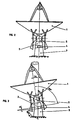
- the antenna positioners are traditionally composed, see FIG. 1, of a fixed element 3 generally consisting of a tower on which is mounted a load support element 2 called “azimuth assembly".
- the upper part of this "azimuth assembly” (2) rotates around the vertical axis, and on this support element is fixed a “site assembly” 5 comprising a horizontal axis which allows the articulation of a "support assembly antenna "1 called” aerial ".
- the moving plate of the "azimuth assembly" 2 equipped with the “site assembly” 5 and the "aerial" 1 constitutes the rotating load.
- the assembly of the "azimuth unit" 2 on the tower 3 is carried out on a horizontal plane.
- the current state of the art further comprises the types of antenna positioning shown in FIGS. 2 and 4, comprising an orientation and positioning device.
- These devices include an additional intermediate element 4 located between the tower 3 and the "azimuth assembly" 2, an element designated by “corner” in what follows.
- the "corner” determines two assembly planes and at least one of these planes is inclined relative to the horizontal plane.
- the two assemblies are produced by means allowing the rotation of an element relative to that which is adjacent to it.
- FIG. 2 An initial position is shown in FIG. 2 when the "corner” 4 is arranged in such a way that the axis of the azimuth unit "2 is common with the axis of the tower 3.
- FIG. 4 Another reference position is shown in Figure 4 when the "corner” 4 is arranged so that the axis of the "azimuth unit" 2 is offset by a value B relative to the axis of the tower 3.
- Figures 3 and 5 show the effect characterizing the usual use of the "corner".
- a 180 ° rotation of the "corner” angularly orients the original axis of the sets 1, 2 and 5 by a value 2A equal to twice the value of the angle A formed by the two planes of the "corner".
- the new orientation is located in the quadrant adjacent to that containing the original axis and is offset, relative to the vertical axis, by an angle equal to 2A - B, see Figure 5.
- angle B is equal to the angle A
- angle A provides two equal and opposite orientations, relative to the vertical axis of the tower 3, of value equal to A.
- the axes of articulations of the "aerial" 1 on the "site assembly" 5 are located on the same vertical plane.
- the "corner” positioners comprising two assembly planes, one of which is inclined with respect to the other, can use the "azimuth assembly” 2 by making it integral with the tower 3.
- FR-A 2 039 484 already discloses a device for orienting and angularly positioning the axis of rotation of a rotating load.
- This device comprises a basic fixed element, an intermediate element and a load support element.
- the intermediate element can rotate relative to the base element about a first axis inclined relative to the horizontal plane.
- the load support member can rotate relative to the intermediate member about a second axis inclined relative to the first.
- this device requires, for its implementation, a double system of drive means.
- First means ensuring the relative rotation of the load support element with respect to the intermediate element
- second means ensuring the relative rotation of the intermediate element with respect to the base fixed element.
- the object of the present invention is to orient and position the axis of rotation of a load rotating intermittently by using the proper means for driving and analyzing the positioning of this load around the axis of rotation of the load. '"azimuth set".
- this device further comprises means for analyzing the relative angular position of the support element with respect to the intermediate element.
- the means of assembly between two adjacent elements is constituted by bearings or a crown, either ball or roller.
- the assembly means is a plain bearing.
- the assembly is carried out by rotating rollers in supports integral with an element and rolling in a slide integral with the adjacent element.
- the means for moving the support element in relative rotation comprises a motor element fixed to the intermediate element and equipped with a toothed pinion meshing with a toothed wheel secured to the angularly movable support element.
- the motor element is fixed on the angularly movable support element and the toothed wheel is integral with the intermediate element.
- the motor element is a gear motor or an electric motor.
- the motor element is a hydraulic motor.
- the means for moving the support element in relative rotation is manual.
- the device according to the invention uses the means for moving the support element in relative rotation to carry out the rotary drive of the intermediate element when the angularly movable support element is integral with the fixed element.
- the means for analyzing the angular position of the support element is a rotary measuring element, either potentiometric, incremental or absolute, fixed on the same element that the motor element and equipped with a toothed pinion meshing with the toothed wheel integral, either of the angularly movable support element, or of the intermediate element, or with a particular toothed wheel integral with the previous one.
- the device according to the invention uses the means for analyzing the angular position of the support element to analyze the angular positioning of the intermediate element with respect to an origin of positioning of this element with respect to the fixed element.
- the means for securing the angularly movable support element and the fixed element consists of a band brake located in the assembly plane of the fixed element with the intermediate element, fixed on the fixed element and wound on a drum integral with the angularly movable support element.
- the means of securing the angularly movable support element and the fixed element is a brake with flexible jaws.
- the brake can be with rigid jaws or disc if its attachment is articulated.
- the means of securing the angularly movable support element and the fixed element consists of at least one bolt, located on one of the elements engaging in at least one keeper located on another element .
- the angularly movable support element and the fixed element can be secured by the combination of a brake and a bolt-keeper assembly.
- the brake or strike actuator can be manual, electromechanical, hydraulic or pneumatic.
- the means for securing the intermediate element and the fixed element is at least one bolt, located on one of the two elements, engaging alternately in at least one keeper located on the other element.
- this securing means is an immobilization device, for example a brake, either with tape, or with jaws, or with disc, associated or not with a pin-strike assembly.
- an immobilization device for example a brake, either with tape, or with jaws, or with disc, associated or not with a pin-strike assembly.
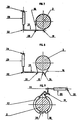
- FIG. 6 given by way of example, makes it possible to understand the operation of the device according to the present invention.
- the external cage 8 of this ring is fixed to the intermediate element 4 on the assembly plane of this element.
- a toothed crown 7 is made integral with the angularly movable support element 2 by its fixing to the internal cage 18 of the ball crown 6.
- a geared motor 12, fixed on the intermediate element 4 comprises an output shaft on which a toothed pinion 13 is keyed meshing with the toothed crown 7.
- a rotary measuring element 14 comprises an output shaft on which a toothed pinion 15 is keyed meshing with the toothed crown 7.
- An actuator 17 comprises a bolt 29, axially movable, pushed by a spring on the face of the internal cage of the ball ring 10 which has two notches forming a keeper disposed at 180 ° degrees from each other, and recalled by a motor means.
- the angularly movable support element 2 has on its axis of rotation a cylindrical projection having at its end a drum on which is wound the band 16 of a brake located in the plane of rotation of the intermediate element 4 relative to the fixed element 3.
- the angle 2A shown exaggerated in FIGS. 3 and 5, being very small, the brake does not require a perfect perpendicularity between the drum and the band due to the elasticity of the latter and the swiveling attachment of its extremities.
- FIG. 7 A section in the plane of the brake is shown in Figure 7.
- the strip 16 wound on the drum of the movable element 2 is fixed at one of its ends to a pivot 19 secured to the fixed element and the other end is attached to a hinge 20 located on a lever 21 hinged itself on the pivot 19.
- An actuator 23, articulated on the one hand on a pivot 20 secured to the fixed element and on the other hand on the end axis 22 of the lever 21, ensures the tension of the strip which causes the braking of the angularly movable support element 2.
- the variant shown in FIG. 8 differs only in its differential arrangement ensured by the attachment of the strip not on the pivot 19 but on a swivel axis 24 of the lever 25.
- FIG. 9 shows a jaw brake 26 and 27 made flexible by a flexible junction 28.
- Figure 6 explains the operation of the device.
- the axis of rotation of the angularly movable support element 2 is oriented by an angular value 2A relative to its original position.
- the support element angularly movable 2 can be rotated from the motor element 12 by the pinion 13 meshing with the ring gear 7.
- the angular analysis of this rotation is carried out by means of the rotary measuring element 14.
- the angularly movable support element 2 is immobilized in rotation by the tension of the band 16 of the brake which secures this element 2 with the fixed element 3.
- the bolt 29 having come out of its keeper, the intermediate element 4 is released and is moved in rotation by the drive means 12, the pinion 13 of which reacts on the ring gear 7 made fixed.
- the bolt 29 is inserted into the keeper of the cage 11 corresponding to this new position, the band 16 of the brake is relaxed and the element 2 can again be rotated from the motor element 12.
- the original position, shown in FIG. 2 is obtained if the inclinations, with respect to the horizontal, of the respective planes of the intermediate element 4 and of the fixed element 3 are equal and have the value of an equal angle to A.
- the value of the orientation can be between 0 and the value 2A, but that in this particular case, the axes of articulation of the '"aerial" 1 are no longer in the original vertical plane.
- This drawback can however be corrected by a readjustment in site of this "aerial" 1 as a function of the angle of rotation of the intermediate element 4.
- the device according to the invention is particularly intended for the orientation and positioning of an antenna positioner intended for the dynamic aiming of non-stationary satellites but can find applications in any system requiring the orientation and positioning of a load rotating intermittently.
Landscapes
- Engineering & Computer Science (AREA)
- Mechanical Engineering (AREA)
- General Engineering & Computer Science (AREA)
- Robotics (AREA)
- Physics & Mathematics (AREA)
- General Physics & Mathematics (AREA)
- Transmission Devices (AREA)
- Variable-Direction Aerials And Aerial Arrays (AREA)
- Pivots And Pivotal Connections (AREA)
- Support Of Aerials (AREA)
Applications Claiming Priority (2)
| Application Number | Priority Date | Filing Date | Title |
|---|---|---|---|
| FR8514580A FR2588049B1 (fr) | 1985-10-02 | 1985-10-02 | Dispositif pour orienter et positionner angulairement l'axe de rotation d'une charge tournante |
| FR8514580 | 1985-10-02 |
Publications (2)
| Publication Number | Publication Date |
|---|---|
| EP0223638A1 EP0223638A1 (fr) | 1987-05-27 |
| EP0223638B1 true EP0223638B1 (fr) | 1989-07-19 |
Family
ID=9323446
Family Applications (1)
| Application Number | Title | Priority Date | Filing Date |
|---|---|---|---|
| EP86402140A Expired EP0223638B1 (fr) | 1985-10-02 | 1986-10-01 | Dispositif pour orienter et positionner angulairement l'axe de rotation d'une charge tournante |
Country Status (7)
| Country | Link |
|---|---|
| US (1) | US4819002A (enExample) |
| EP (1) | EP0223638B1 (enExample) |
| JP (1) | JPS6298801A (enExample) |
| CA (1) | CA1260136A (enExample) |
| DE (1) | DE3664526D1 (enExample) |
| FR (1) | FR2588049B1 (enExample) |
| IL (1) | IL80203A0 (enExample) |
Families Citing this family (22)
| Publication number | Priority date | Publication date | Assignee | Title |
|---|---|---|---|---|
| US5216431A (en) * | 1989-10-27 | 1993-06-01 | Scientific-Atlanta, Inc. | Pedestal assembly having an RFI/EMI labyrinth shield |
| US5075682A (en) * | 1990-03-30 | 1991-12-24 | Dehnert Douglas K | Antenna mount and method for tracking a satellite moving in an inclined orbit |
| FR2672737B1 (fr) * | 1991-02-08 | 1993-04-30 | Europ Agence Spatiale | Dispositif de support et d'entrainement en rotation d'une charge utile par rapport a une structure, notamment pour un mecanisme de pointage d'antenne de satellite. |
| US6161806A (en) * | 1995-01-23 | 2000-12-19 | Idea Development, Engineering And Service, Inc. | Apparatus and method for reducing repetitive stress injury |
| US5657956A (en) * | 1995-08-14 | 1997-08-19 | Idea Development, Engineering And Service, Inc. | Thrust bearing and use of same with apparatus for reducing repetitive stress injury |
| US6034643A (en) * | 1997-03-28 | 2000-03-07 | Kabushiki Kaisha Toyota Chuo Kenkyusho | Directional beam antenna device and directional beam controlling apparatus |
| SE509520C2 (sv) * | 1997-06-06 | 1999-02-08 | Ericsson Telefon Ab L M | Anordning för vinkelinställning av ett riktningsvisande föremål |
| US5860327A (en) * | 1997-06-10 | 1999-01-19 | Stanev; Stefan | Apparatus for two dimensional orientation of an object |
| US6257526B1 (en) | 1998-11-09 | 2001-07-10 | Hughes Electronics Corporation | Satellite system and method of deploying same |
| US7184761B1 (en) | 2000-03-27 | 2007-02-27 | The Directv Group, Inc. | Satellite communications system |
| US7369809B1 (en) | 2000-10-30 | 2008-05-06 | The Directv Group, Inc. | System and method for continuous broadcast service from non-geostationary orbits |
| US6633266B2 (en) * | 2002-03-13 | 2003-10-14 | The Boeing Company | Antenna system incorporating movable platform |
| US6820531B1 (en) * | 2003-12-01 | 2004-11-23 | Textron Systems Corporation | Positioning system with continuous-range inclination and rotation angles |
| US7434843B1 (en) * | 2004-04-07 | 2008-10-14 | Northrop Grumman Corporation | Hollow shaft fluid rotary joint |
| US7046210B1 (en) * | 2005-03-30 | 2006-05-16 | Andrew Corporation | Precision adjustment antenna mount and alignment method |
| US8141452B2 (en) * | 2006-10-26 | 2012-03-27 | Barry Lynn Wood | Rotational motion-positioning apparatus |
| US8151660B2 (en) * | 2007-02-23 | 2012-04-10 | RPY Motion, Inc. | Three axes rotational motion-positioning apparatus |
| EP2186158A1 (en) * | 2007-09-05 | 2010-05-19 | ViaSat, Inc. | Roller based antenna positioner |
| CZ305595B6 (cs) * | 2014-03-27 | 2015-12-30 | Mendelova Univerzita V Brně | Zařízení pro ovládání otáčení kabiny nebo otočného mechanismu |
| DE102015006437B3 (de) * | 2015-05-18 | 2016-08-18 | progenox GmbH | Nivelliereinheit für Kameras oder Sensoren |
| CN109163183B (zh) * | 2018-11-14 | 2023-09-26 | 浙江华东光电仪器有限公司 | 太赫兹单元探测器旋转探测无盲点装置 |
| CN114562974A (zh) * | 2022-03-09 | 2022-05-31 | 广西玉柴机器股份有限公司 | 一种转轴角度测量工装 |
Family Cites Families (14)
| Publication number | Priority date | Publication date | Assignee | Title |
|---|---|---|---|---|
| US3407404A (en) * | 1964-10-05 | 1968-10-22 | Bell Telephone Labor Inc | Directive microwave antenna capable of rotating about two intersecting axes |
| FR2039484A5 (enExample) * | 1969-04-08 | 1971-01-15 | Pineau Louis | |
| GB1267117A (enExample) * | 1970-03-13 | 1972-03-15 | ||
| US3712481A (en) * | 1971-12-23 | 1973-01-23 | Mc Donnell Douglas Corp | Actuator |
| DE2357470C3 (de) * | 1973-11-17 | 1980-04-10 | Magirus-Deutz Ag, 7900 Ulm | Vorrichtung zum lotrechten Ausrichten der Hochachse eines höhenveränderlichen Arbeitsgerätes, z.B. einer mehrteiligen Feuerwehrleiter |
| GB1571903A (en) * | 1977-06-28 | 1980-07-23 | Secr Defence | Stabilising mounting |
| US4181283A (en) * | 1978-02-21 | 1980-01-01 | TRW Inc. Systems & Energy | Rotary mount characterized by variable coning motion |
| FR2486293B1 (fr) * | 1980-07-04 | 1986-11-21 | Europ Agence Spatiale | Nouveau dispositif d'orientation et de positionnement d'une charge utile |
| SE435652B (sv) * | 1982-12-29 | 1984-10-08 | Ericsson Telefon Ab L M | Anordning for instellning av en apparatplattforms plan i en valbar lutning |
| DE3306056C1 (de) * | 1983-02-22 | 1984-09-06 | Erich Dr. 5552 Morbach Faber | Vorrichtung zum Ausrichten der Zahnlängsachsen einzelner Zahnstümpfe eines Zahnmodelles |
| DE3307069A1 (de) * | 1983-03-01 | 1984-09-06 | Rheinmetall GmbH, 4000 Düsseldorf | Einrichtung zum horizontieren einer drehbaren waffenplattform |
| FR2562459B1 (fr) * | 1984-02-07 | 1986-05-23 | Gabillet Maurice | Bras de manipulation modulaire |
| SE441697B (sv) * | 1984-03-20 | 1985-10-28 | Ericsson Telefon Ab L M | Anordning for instellning av en apparatplattforms plan i en valbar lutning och vridning |
| US4617572A (en) * | 1984-08-14 | 1986-10-14 | Albert Hugo | Television dish antenna mounting structure |
-
1985
- 1985-10-02 FR FR8514580A patent/FR2588049B1/fr not_active Expired
-
1986
- 1986-09-30 IL IL80203A patent/IL80203A0/xx not_active IP Right Cessation
- 1986-09-30 US US06/913,375 patent/US4819002A/en not_active Expired - Fee Related
- 1986-10-01 DE DE8686402140T patent/DE3664526D1/de not_active Expired
- 1986-10-01 EP EP86402140A patent/EP0223638B1/fr not_active Expired
- 1986-10-02 CA CA000519634A patent/CA1260136A/fr not_active Expired
- 1986-10-02 JP JP61235433A patent/JPS6298801A/ja active Granted
Also Published As
| Publication number | Publication date |
|---|---|
| CA1260136A (fr) | 1989-09-26 |
| FR2588049B1 (fr) | 1989-06-02 |
| IL80203A0 (en) | 1986-12-31 |
| JPH0511801B2 (enExample) | 1993-02-16 |
| US4819002A (en) | 1989-04-04 |
| JPS6298801A (ja) | 1987-05-08 |
| DE3664526D1 (en) | 1989-08-24 |
| FR2588049A1 (fr) | 1987-04-03 |
| EP0223638A1 (fr) | 1987-05-27 |
Similar Documents
| Publication | Publication Date | Title |
|---|---|---|
| EP0223638A1 (fr) | Dispositif pour orienter et positionner angulairement l'axe de rotation d'une charge tournante | |
| FR2644542A1 (fr) | Dispositif tendeur a reglage par ressort | |
| FR2502363A1 (fr) | Dispositif de reglage pour machines a affranchir et machines a timbrer | |
| FR2545624A1 (fr) | Dispositif d'actionnement electromecanique compact | |
| FR2574144A1 (fr) | Derailleur arriere pour une bicyclette | |
| FR2459054A1 (fr) | Appareil de traitement therapeutique par rayonnement et dispositif d'arret du faisceau retractable, destine a cet appareil | |
| FR2542122A1 (fr) | Dispositif de support et d'orientation d'un element optique pour instrument analytique | |
| EP1221000B1 (fr) | Dispositif de tension dans les transmissions de mouvements de rotation par courroies, chaines ou cables | |
| FR2753249A1 (fr) | Procede d'assemblage d'un reducteur epicycloidal et reducteur epicycloidal | |
| WO2003102437A1 (fr) | Actionneur a deux moteurs, un reducteur differentiel et un limiteur de couple | |
| EP0448021B1 (fr) | Système de levage d'une charge à deux tambours fonctionnant en parallèle et synchronisés en rotation | |
| EP0317596B1 (fr) | Dispositif de verrouillage pour pince de prehension d'un telemanipulateur | |
| EP1964778A1 (fr) | Pivot traversant à lames | |
| EP0229681B1 (fr) | Dispositif d'entraînement en rotation du tube d'enroulage d'un store à rouleau, volet roulant ou similaire | |
| EP0267078B1 (fr) | Ensemble de palier de rampe de détection de position pour un inverseur de poussée de turbosoufflante | |
| FR3060679A1 (fr) | Systeme d'ancrage pour un axe | |
| FR2622945A1 (fr) | Mecanisme d'entrainement debrayable pour couronne tournante | |
| EP1272779B1 (fr) | Disposition d'assemblage de cames sur un arbre de commande commun | |
| FR2758756A1 (fr) | Ensemble d'usinage par bande abrasive d'une portee cylindrique d'une piece | |
| EP4187126B1 (fr) | Système réducteur à engrenages et bagues dentées pour un moteur d'un ensemble occultant où le système réducteur présente un bruit de fonctionnement réduit | |
| EP0498699B1 (fr) | Mécanisme de pointage d'une charge utile, notamment d'une antenne de satellite | |
| EP0247917A1 (fr) | Mécanisme pour transformer un mouvement rectiligne alternatif en un mouvement de rotation pas à pas | |
| FR3095480A3 (fr) | Liaison entre deux éléments montés articulés l’un à l’autre. | |
| EP0010016B1 (fr) | Mécanisme de commande du déplacement d'une règle mobile parallèlement à elle-même sur une planche à dessin | |
| EP0767366A1 (fr) | Broche d'entraînement en rotation à montage rapide, et machine comportant une telle broche |
Legal Events
| Date | Code | Title | Description |
|---|---|---|---|
| PUAI | Public reference made under article 153(3) epc to a published international application that has entered the european phase |
Free format text: ORIGINAL CODE: 0009012 |
|
| 17P | Request for examination filed |
Effective date: 19861018 |
|
| AK | Designated contracting states |
Kind code of ref document: A1 Designated state(s): BE CH DE FR GB IT LI NL SE |
|
| 17Q | First examination report despatched |
Effective date: 19880729 |
|
| GRAA | (expected) grant |
Free format text: ORIGINAL CODE: 0009210 |
|
| AK | Designated contracting states |
Kind code of ref document: B1 Designated state(s): BE CH DE FR GB IT LI NL SE |
|
| ITF | It: translation for a ep patent filed | ||
| REF | Corresponds to: |
Ref document number: 3664526 Country of ref document: DE Date of ref document: 19890824 |
|
| PGFP | Annual fee paid to national office [announced via postgrant information from national office to epo] |
Ref country code: BE Payment date: 19890908 Year of fee payment: 4 |
|
| GBT | Gb: translation of ep patent filed (gb section 77(6)(a)/1977) | ||
| PGFP | Annual fee paid to national office [announced via postgrant information from national office to epo] |
Ref country code: CH Payment date: 19890925 Year of fee payment: 4 |
|
| PGFP | Annual fee paid to national office [announced via postgrant information from national office to epo] |
Ref country code: NL Payment date: 19891031 Year of fee payment: 4 |
|
| PGFP | Annual fee paid to national office [announced via postgrant information from national office to epo] |
Ref country code: SE Payment date: 19900419 Year of fee payment: 4 |
|
| PLBE | No opposition filed within time limit |
Free format text: ORIGINAL CODE: 0009261 |
|
| STAA | Information on the status of an ep patent application or granted ep patent |
Free format text: STATUS: NO OPPOSITION FILED WITHIN TIME LIMIT |
|
| 26N | No opposition filed | ||
| PG25 | Lapsed in a contracting state [announced via postgrant information from national office to epo] |
Ref country code: SE Effective date: 19901002 |
|
| PG25 | Lapsed in a contracting state [announced via postgrant information from national office to epo] |
Ref country code: LI Effective date: 19901031 Ref country code: CH Effective date: 19901031 Ref country code: BE Effective date: 19901031 |
|
| BERE | Be: lapsed |
Owner name: SOC. NATIONALE D'ETUDE ET DE CONSTRUCTION DE MOTEU Effective date: 19901031 |
|
| PG25 | Lapsed in a contracting state [announced via postgrant information from national office to epo] |
Ref country code: NL Effective date: 19910501 |
|
| NLV4 | Nl: lapsed or anulled due to non-payment of the annual fee | ||
| REG | Reference to a national code |
Ref country code: CH Ref legal event code: PL |
|
| ITTA | It: last paid annual fee | ||
| REG | Reference to a national code |
Ref country code: FR Ref legal event code: TP |
|
| REG | Reference to a national code |
Ref country code: GB Ref legal event code: 732 |
|
| ITPR | It: changes in ownership of a european patent |
Owner name: CESSIONE;SOCIETE TECHNIQUE D'APPLICATION ET DE REC |
|
| EUG | Se: european patent has lapsed |
Ref document number: 86402140.7 Effective date: 19910603 |
|
| PGFP | Annual fee paid to national office [announced via postgrant information from national office to epo] |
Ref country code: GB Payment date: 19950926 Year of fee payment: 10 |
|
| PGFP | Annual fee paid to national office [announced via postgrant information from national office to epo] |
Ref country code: DE Payment date: 19951018 Year of fee payment: 10 |
|
| PG25 | Lapsed in a contracting state [announced via postgrant information from national office to epo] |
Ref country code: GB Effective date: 19961001 |
|
| GBPC | Gb: european patent ceased through non-payment of renewal fee |
Effective date: 19961001 |
|
| PG25 | Lapsed in a contracting state [announced via postgrant information from national office to epo] |
Ref country code: DE Effective date: 19970701 |
|
| PGFP | Annual fee paid to national office [announced via postgrant information from national office to epo] |
Ref country code: FR Payment date: 19970731 Year of fee payment: 12 |
|
| PG25 | Lapsed in a contracting state [announced via postgrant information from national office to epo] |
Ref country code: FR Free format text: LAPSE BECAUSE OF NON-PAYMENT OF DUE FEES Effective date: 19990630 |
|
| REG | Reference to a national code |
Ref country code: FR Ref legal event code: ST |
|
| PG25 | Lapsed in a contracting state [announced via postgrant information from national office to epo] |
Ref country code: IT Free format text: LAPSE BECAUSE OF NON-PAYMENT OF DUE FEES;WARNING: LAPSES OF ITALIAN PATENTS WITH EFFECTIVE DATE BEFORE 2007 MAY HAVE OCCURRED AT ANY TIME BEFORE 2007. THE CORRECT EFFECTIVE DATE MAY BE DIFFERENT FROM THE ONE RECORDED. Effective date: 20051001 |