EP0223208B1 - Method and apparatus for the regulation of turbo compressors - Google Patents
Method and apparatus for the regulation of turbo compressors Download PDFInfo
- Publication number
- EP0223208B1 EP0223208B1 EP86115792A EP86115792A EP0223208B1 EP 0223208 B1 EP0223208 B1 EP 0223208B1 EP 86115792 A EP86115792 A EP 86115792A EP 86115792 A EP86115792 A EP 86115792A EP 0223208 B1 EP0223208 B1 EP 0223208B1
- Authority
- EP
- European Patent Office
- Prior art keywords
- blow
- controller
- variable
- curve
- reference variable
- Prior art date
- Legal status (The legal status is an assumption and is not a legal conclusion. Google has not performed a legal analysis and makes no representation as to the accuracy of the status listed.)
- Expired - Lifetime
Links
- 238000000034 method Methods 0.000 title claims description 9
- 230000003321 amplification Effects 0.000 claims description 8
- 238000003199 nucleic acid amplification method Methods 0.000 claims description 8
- 230000000694 effects Effects 0.000 claims description 3
- 238000011144 upstream manufacturing Methods 0.000 claims 1
- 230000006870 function Effects 0.000 description 7
- 230000000875 corresponding effect Effects 0.000 description 5
- 238000010586 diagram Methods 0.000 description 3
- 238000005086 pumping Methods 0.000 description 3
- 230000006399 behavior Effects 0.000 description 2
- 230000001276 controlling effect Effects 0.000 description 2
- 230000001105 regulatory effect Effects 0.000 description 2
- 230000006978 adaptation Effects 0.000 description 1
- 238000013459 approach Methods 0.000 description 1
- 230000003247 decreasing effect Effects 0.000 description 1
- 238000007620 mathematical function Methods 0.000 description 1
- 230000000737 periodic effect Effects 0.000 description 1
- 238000005728 strengthening Methods 0.000 description 1
Images
Classifications
-
- F—MECHANICAL ENGINEERING; LIGHTING; HEATING; WEAPONS; BLASTING
- F04—POSITIVE - DISPLACEMENT MACHINES FOR LIQUIDS; PUMPS FOR LIQUIDS OR ELASTIC FLUIDS
- F04D—NON-POSITIVE-DISPLACEMENT PUMPS
- F04D27/00—Control, e.g. regulation, of pumps, pumping installations or pumping systems specially adapted for elastic fluids
- F04D27/02—Surge control
- F04D27/0207—Surge control by bleeding, bypassing or recycling fluids
Definitions
- the invention relates to a method for regulating turbo compressors for preventing pumping, of the type specified in the preamble of claim 1, and a device for carrying out the method
- pumps are the intermittent or periodic backflow of the medium from the pressure to the suction side. This condition occurs e.g. if the final pressure or final pressure / suction pressure ratio and / or the throughput are too low.
- a surge limit line can therefore be clearly defined in the map, which divides the map into the stable and unstable area.
- the surge line is usually curved, i.e. it has different slopes in different areas of the map. In the frequently used map display with throughput and pressure as coordinates, for example, the surge line is flatter with increasing pressure. The same applies to other possible characteristic diagram representations with guide vane position, speed, head of the compressor or the like.
- a blow-off line is defined at a safety distance parallel to the surge line, and when the current operating point approaches the blow-off line, a blow-off valve is opened more or less so that the actual value of a controlled variable, in particular the throughput, is based on the Blow-off line and the reference variable, especially the final pressure, do not exceed the setpoint.
- a controlled variable in particular the throughput
- the throughput serves as a reference variable for forming the setpoint and the final pressure is the controlled variable to be regulated to the setpoint.
- the result of the curved course of the blow-off line is that a predetermined change in the command variable at different points on the blow-off line results in changes in the desired value for the controlled variable of different sizes. This affects the strengthening of the control loop to different degrees.
- Pump limit controllers are safety controllers and are usually activated so that they work close to the stability limit in order to ensure the best possible compressor protection.
- the position of the stability limit is very much influenced by the overall gain of the control loop. A high overall gain is most likely to lead to instability.
- the gain factor of the actual controller is therefore set in such a way that, together with the gain resulting from the slope of the blow-off line, it leads to an overall gain within the stability limit.
- the area of the blow-off line in which the highest gain is effective must be used. In other areas of the blow-off line, which may also include the most common arberite areas, the control loop is then not optimally adjusted.
- the strongly curved course of the blow-off line therefore has the consequence that a surge limit controller with fixed control parameters is not optimally adjusted in wide working areas.
- a method of the type mentioned is known from FR-A-2 352 970.
- the gain of the controller can be changed as a function of the control difference, in such a way that the gain factor is increased when the control difference takes a negative value. This can ensure that the control loop reacts quickly when the current operating point crosses the blow-off line towards the surge limit line. Since the gain is only a function of the control difference, it is independent of the course of the blow-off line, and the different slope of the blow-off line in the map has a corresponding effect on the overall loop gain.
- the object of the invention is to provide a method of the type mentioned at the outset and a device for carrying it out, with which an adaptation of the control behavior to the requirements in the different areas of the characteristic diagram is possible.
- the invention is based on the basic idea of compensating for the effects of the slope of the curved blow-off line, which changes according to the command variable, on the overall gain of the control loop by a correspondingly opposite change in the gain factor of the controller, so that there is a largely constant overall gain of the control loop in the entire working range.
- This basic principle can also be approximated by switching between two or a few different values of the gain factor of the controller.
- the pressure in front of and behind a throttle orifice is measured in the suction port 1 of a compressor K by means of sensors 3.5, from which a transmitter 7 forms the actual value for the compressor throughput V on the suction side.
- a sensor 9 detects the actual value of the final pressure P, which is entered into a computer 13 via a transmitter 11.
- the computer 13 is connected to a memory 15 in which the course of the blow-off line A is stored in the compressor map given by P and V.
- the computer 13 determines a setpoint for the through from the actual value of P and the blow-off line Set V.
- a differential element 17 Actual and setpoint are compared in a differential element 17 and the difference is fed as an input signal to a controller 19, which can have a proportional-integral and / or differential behavior and whose Aussenassignal is a manipulated variable for a relief valve 21 branching off from the compressor outlet or for Return nozzle return blow valve delivers.
- the steep lower course of the blow-off line A corresponds to a small gain and the flat upper course to a high gain. If, on the other hand, what is also known is reversed, the role of the command variable and the controlled variable and the throughput V is used as the command variable for determining a desired value of the final pressure P, the conditions are reversed and the gain is large and flat in the steep part of the blow-off line Part small.
- the total gain of the control loop is the sum of the gain resulting from the slope of the blow-off line and the gain factor of the controller 19 plus the so-called system gain, i.e. the gain factors specified by the controlled system, in particular the compressor and the relief valve.
- the gain factor in the controller 19 is therefore changed according to the invention.
- the course of the slope S of the blow-off line A is also specified as a function in the memory 15.
- the computer 13 determines the associated value of the slope of the blow-off line and generates a corresponding control signal which is fed to a control input of the controller 19 and there causes a corresponding change in the gain factor of the controller 19.
- the computer 13 can also calculate its slope from the values of the blow-off line A belonging to different values of P.
- the actual value of P is not supplied to a computer, but rather to a simple function generator 23, which permanently assigns a desired value for V to each actual value of P in accordance with a predetermined relationship corresponding to the blow-off line.
- the actual value of P is fed to a second function generator 25, which permanently assigns a corresponding value for the slope of the blow-off line to each actual value of P, which is then fed as a control signal to controller 19 for controlling the amplification factor.
- the actual value of P is likewise fed to the function generator 23 and also to a comparator 27 which compares the actual value of P with predetermined upper and lower limit values Pmax, P min. As long as the actual value of P is within this limit, the gain factor of the controller 19 remains unchanged. If P max is exceeded or Pmin is undershot, the gain factor of controller 19 is increased or decreased by a fixed, predetermined value. This corresponds to an approximation of the curved course of the blow-off line through three straight sections with different slopes, the middle straight section running between the limit values Pmin, Pmax. In an even simpler embodiment, which corresponds to an approximation of the blow-off line by only two straight sections, the gain factor is switched between two values depending on whether a single limit value is exceeded or not reached.
- blow-off line in the memory 15 can also not be predetermined by a table of values but by a mathematical function.
- a course of the blow-off line approximated by two or more straight line sections can be predetermined in the function generator 25.
- the described mode of operation is not tied to the selected map display with the coordinates final pressure and volume flow, but can also be adapted to any other map display familiar to a person skilled in the art.
Description
Die Erfindung betrifft ein Verfahren zum Regeln von Turbokompressoren zum Verhindern des Pumpens, von der im Oberbegriff des Anspruchs 1 angegebenen Art, sowie eine Einrichtung zur Durchführung des VerfahrensThe invention relates to a method for regulating turbo compressors for preventing pumping, of the type specified in the preamble of claim 1, and a device for carrying out the method
Als Pumpen bezeichnet man bei Kompressoren das stoßweise oder periodische Rückströmen von Fördermedium von der Druck- zur Saugseite. Dieser Zustand tritt z.B. bei zu hohem Enddruck bzw. Enddruck/Saugdruck-Verhältnis und/oder zu niedrigem Durchsatz ein. Im Kennfeld kann deshalb eine Pumpgrenzlinie eindeutig definiert werden, die das Kennfeld in den stabilen und instabilen Bereich teilt. Die Pumpgrenzlinie ist in der Regel gekrümmt, d.h. sie hat in verschiedenen Bereichen des Kennfeldes unterschiedliche Steigungen. In der häufig verwendeten Kennfelddarstellung mit Durchsatz und Druck als Koordinaten z.B., verläuft die Pumpgrenzlinie bei steigendem Druck flacher. Für andere mögliche Kennfelddarstellungen mit Leitschaufelstellung, Drehzahl, Förderhöhe des Kompressors oder dgl. gilt entsprechendes.In compressors, pumps are the intermittent or periodic backflow of the medium from the pressure to the suction side. This condition occurs e.g. if the final pressure or final pressure / suction pressure ratio and / or the throughput are too low. A surge limit line can therefore be clearly defined in the map, which divides the map into the stable and unstable area. The surge line is usually curved, i.e. it has different slopes in different areas of the map. In the frequently used map display with throughput and pressure as coordinates, for example, the surge line is flatter with increasing pressure. The same applies to other possible characteristic diagram representations with guide vane position, speed, head of the compressor or the like.
Um Kompressoren vor dem Pumpen zu schützen, wird in einem Sicherheitsabstand parallel zur Pumpgrenzlinie eine Abblaselinie definert, und bei Annäherung des momentanen Arbeitspunktes an die Abblaselinie wird ein Abblaseventil mehr oder weniger geöffnet, so daß der Istwert einer Regelgröße, insbesondere des Druchsatzes, einen anhand der Abblaselinie und der Führungsgröße, insbesondere des Enddrucks, ermittelten Sollwert nich übersteigt. Es gibt auch Regelungen, bei denen der Durchsatz als Führungsgröße zur Bildung des Sollwerts dient und der Enddruck die auf den Sollwert zu regelnde Regelgröße ist.In order to protect compressors from pumping, a blow-off line is defined at a safety distance parallel to the surge line, and when the current operating point approaches the blow-off line, a blow-off valve is opened more or less so that the actual value of a controlled variable, in particular the throughput, is based on the Blow-off line and the reference variable, especially the final pressure, do not exceed the setpoint. There are also regulations in which the throughput serves as a reference variable for forming the setpoint and the final pressure is the controlled variable to be regulated to the setpoint.
Der gekrümmte Verlauf der Abblaselinie hat zur Folge, daß eine vorgegebene Änderung der Führungsgröße an verschiedenen Stellen der Abblaselinie unterschiedlich große Änderungen des Sollwerts für die Regelgröße zur Folge hat. Dies wirkt sich als unterschiedlich starke Verstärkung im Regelkreis aus.The result of the curved course of the blow-off line is that a predetermined change in the command variable at different points on the blow-off line results in changes in the desired value for the controlled variable of different sizes. This affects the strengthening of the control loop to different degrees.
Pumpgrenzregler sind Sicherheitsregler und werden in der Regel so aktiviert, daß sie nahe der Stabilitätsgrenze arbeiten, um einen bestmöglichen Kompressorschutz zu gewährleisten. Die Lage der Stabilitätsgrenze wird sehr stark von der Gesamtverstärkung des Regelkreises beeinflußt. Eine hohe Gesamtverstärkung führt am ehesten zu Instabilität.Pump limit controllers are safety controllers and are usually activated so that they work close to the stability limit in order to ensure the best possible compressor protection. The position of the stability limit is very much influenced by the overall gain of the control loop. A high overall gain is most likely to lead to instability.
Der Verstärkungsfaktor des eigentlichen Reglers wird deshalb so eingestellt, daß er zusammen mit der sich aus der sich aus der Steigung der Abblaselinie ergebenden Verstärkung noch zu einer innerhalb der Stabilitätsgrenze liegenden Gesamtverstärkung führt. Hierbei ist selbstverständlich auf den Bereich der Abblaselinie abzustellen, in welchem die höchste Verstärkung wirksam ist In anderen Bereichen der Abblaselinie, zu denen auch die häufigsten Arberitsbereiche gehören können, ist der Regelkreis dann nicht optimal justiert. Der stark gekrümmte Verlauf der Abblaselinie hat deshalb zur Folge, daß ein Pumpgrenzregler mit festeingestellten Regelparamentern in weiten Arbeitsbereichen nicht optimal justiert ist.The gain factor of the actual controller is therefore set in such a way that, together with the gain resulting from the slope of the blow-off line, it leads to an overall gain within the stability limit. Of course, the area of the blow-off line in which the highest gain is effective must be used. In other areas of the blow-off line, which may also include the most common arberite areas, the control loop is then not optimally adjusted. The strongly curved course of the blow-off line therefore has the consequence that a surge limit controller with fixed control parameters is not optimally adjusted in wide working areas.
Ein Verfahren der eingangs genannten Art ist aus der FR-A-2 352 970 bekannt. Bei dieser bekannten Regelung ist die Verstärkung des Reglers in Abhängigkeit von der Regeldifferenz veränderbar, und zwar derart, daß der Verstärkungsfaktor erhöht wird, wenn die Regeldifferenz einen negativen Wert annimmt. Dadurch kann sichergestellt werden, dass der Regelkreis schnell reagiert, wenn der derzeitige Arbeitspunkt die Abblaselinie in Richtung auf die Pumpgrenzlinie überschreitet. Da die Verstärkung ausschließlich eine Funktion der Regeldifferenz ist, ist sie unabhängig vom Verlauf der Abblaselinie, und die unterschiedliche Steigung der Abblaselinie im Kennfeld wirkt sich entsprechend auf die Gesamtkreisverstärkung aus.A method of the type mentioned is known from FR-A-2 352 970. In this known control, the gain of the controller can be changed as a function of the control difference, in such a way that the gain factor is increased when the control difference takes a negative value. This can ensure that the control loop reacts quickly when the current operating point crosses the blow-off line towards the surge limit line. Since the gain is only a function of the control difference, it is independent of the course of the blow-off line, and the different slope of the blow-off line in the map has a corresponding effect on the overall loop gain.
Aufgabe der Erfindung ist es, ein Verfahren der eingangs genannten Art und eine Einrichtung zu seiner Durchführung zu schaffen, mit dem eine Anpassung des Regelverhaltens an die Erfordernisse in den verschiedenen Bereichen des Kennfeldes möglich ist.The object of the invention is to provide a method of the type mentioned at the outset and a device for carrying it out, with which an adaptation of the control behavior to the requirements in the different areas of the characteristic diagram is possible.
Die Lösung der Aufgabe ist im Anspruch 1 angegeben. Die Unteransprüche beziehen sich auf vorteilhafte weitere Ausgestaltungen.The solution to the problem is specified in claim 1. The subclaims relate to advantageous further refinements.
Die Erfindung beruht auf dem Grundgedanken, die Auswirkungen der sich entsprechend der Führungsgröße ändernden Steigung der gekrümmten Abblaselinie auf die Gesamtverstärkung des Regelkreises durch eine entsprechend gegenläufige Anderung des Verstärkungsfaktors des Reglers auszugleichen, so daß sich im gesamten Arbeitsbereich eine weitgehend konstante Gesamtverstärkung des Regelkreises ergibt. Dieses Grundprinzip kann aber auch durch Umschaltung zwischen zwei oder wenigen unterschiedlichen Werten des Verstärkungsfaktors des Reglers approximiert werden.The invention is based on the basic idea of compensating for the effects of the slope of the curved blow-off line, which changes according to the command variable, on the overall gain of the control loop by a correspondingly opposite change in the gain factor of the controller, so that there is a largely constant overall gain of the control loop in the entire working range. This basic principle can also be approximated by switching between two or a few different values of the gain factor of the controller.
Ausführungsformen der Erfindung werden im folgenden anhand der Zeichnungen näher erläutert. Es zeigt:
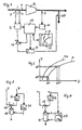
- Fig. 1 ein vereinfachtes Schema einer Einrichtung zur Regelung eines Turbokompressors zum Verhindern des Pumpens;
- Fig. 2 schematisch den Verlauf der pumpgrenzlinie und Abblaselinie im Kennfeld des Kompressors;
- Fig. 3 eine Teil einer vereinfachten Ausführungsform der Regeleinrichtung;
- Fig. 4 ein Detail einer weiteren Ausführungsform der Regeleinrichtung.
- Figure 1 is a simplified diagram of a device for controlling a turbo compressor to prevent pumping.
- Fig. 2 shows schematically the course of the pump limit line and blow-off line in the map of the compressor;
- 3 shows a part of a simplified embodiment of the control device;
- Fig. 4 shows a detail of a further embodiment of the control device.
Gemäß Fig. 1 wird im Saugstutzen 1 eines Kompressors K durch Meßfühler 3,5 der Druck vor und hinter einer Drosselblende gemessen, woraus ein Meßumformer 7 den Istwert für den saugseitigen Kompressordurchsatz V bildet. Am Kompressorausgang erfaßt ein Meßfühler 9 den Istwert des Enddruckes P, der über einen Meßumformer 11 in einen Rechner 13 eingegeben wird. Der Rechner 13 ist mit einem Speicher 15 verbunden, in welchem der Verlauf der Abblaselinie A in dem durch P und V gegebenen Kompressorkennfeld abgespeichert ist. Aus dem Istwert von P und der Abblaselinie ermittelt der Rechner 13 einen Sollwert für den Durchsatz V. Ist- und Sollwert werden in einem Differenzglied 17 verglichen und die Differenz als Eingangssignal einem Regler 19 zugeführt, der ein Proportional-Integral- und/oder Differentialverhalten aufweisen kann und dessen Ausgenassignal eine Stellgröße für ein vom Kompressoraustritt abzweigendes Abblaseventil 21 oder ein zum Saugstutzen zurückführendes Umblaseventil liefert.According to FIG. 1, the pressure in front of and behind a throttle orifice is measured in the suction port 1 of a compressor K by means of sensors 3.5, from which a
Wie in Fig. 2 dargestellt, verläuft im Kompressorkennfeld, welches durch den Durchsatz V als Abszisse und den Enddruck P (oder auch das Enddruck/Saugdruck-Verhältnis) als Ordinate gegeben ist, die Pumpgrenzlinie PG und die in einem Sicherheitsabstand rechts davon verlaufende Abblaselinie A jeweils gekrümmt. Dies hat zur Folge, daß eine bestimmte Änderung A P des als Führungsgröße diendenden Enddrucks unterschiedlich großen Änderungen A V bzw. A V' des Sollwertes für den Durchsatz entsprechen. Da der als Sollwertgeber dienende Speicher 15 mit dem Rechner 13 Teil des Regelkreises ist, wirken sich diese Unterschiede als Änderungen in der Gesamtverstärkung des Regelkreises aus, falls der Regler 19 einen konstanten Verstärkungsfaktor hat. In Fig. 2 entspricht der Steile untere Verlauf der Abblaselinie A einer kleinen Verstärkung und der flache obere Verlauf einer hohen Verstärkung. Wird dagegen, was ebenfalls bekannt ist, die Rolle von Führungs- und Regelgröße vertauscht und der Durchsatz V als Führungsgröße zur Bestimmung eines Sollwertes des Enddrucks P verwendet, dann kehren sich die Verhältnisse um und die Verstärkung ist im steilen Teil der Abblaselinie Groß und im flachen Teil klein.As shown in Fig. 2, in the compressor map, which is given by the flow rate V as the abscissa and the final pressure P (or also the final pressure / suction pressure ratio) as the ordinate, the surge line PG and the blow-off line A running at a safety distance to the right of it each curved. The result of this is that a certain change A P in the final pressure serving as the reference variable corresponds to changes A V or A V 'of the setpoint for the throughput of different sizes. Since the
Die Gesamtverstärkung des Regelkreises ist die Summe der sich aus der Steigung der Abblaselinie ergebenden Verstärkung und dem Verstärkungsfaktor des Reglers 19 plus der sogenannten Streckenverstärkung, d.h. den durch die Regelstrecke, insbesondere dem Kompressor und dem Abblaseventil vorgegebenen Verstärkungsfaktoren. Um eine möglichst in allen Bereichen konstante Verstärkung zu erzielen, wird deshalb erfindungsgemäß der Verstärkungsfaktor im Regler 19 geändert. Bei der Ausführungsform nach Fig. 1 ist im Speicher 15 außer dem Verlauf der Abblaselinie A auch der Verlauf der Steigung S der Abblaselinie A als Funktion vorgegeben. Der Rechner 13 ermittelt für jeden Istwert der Führungsgröße P den zugehörigen Wert der Steigung der Abblaselinie und erzeugt ein entsprechendes Steurersignal, welches einem Steuereingang des Reglers 19 zugeführt und dort eine entsprechende Änderung des Verstärkungsfaktors des Reglers 19 bewirkt.The total gain of the control loop is the sum of the gain resulting from the slope of the blow-off line and the gain factor of the
Anstatt den jeweiligen Wert der Steigung der Abblaselinie A aus dem Speicher 15 abzurufen, kann der Rechner 13 auch aus den zu verschiedenen Werten von P gehörenden Werten der Abblaselinie A deren Steigung ausrechnen.Instead of retrieving the respective value of the slope of the blow-off line A from the
Bei der vereinfachten Ausführungsform nach Fig. 3 wird der Istwert von P nicht einem Rechner, sondern einem einfachen Funktionsgeber 23 zugeführt, welcher jedem Istwert von P einen Sollwert für V entsprechend einem vorgegebenen, der Abblaselinie entsprechenden Zusammenhang fest zuordnet. Außerdem wird der Istwert von P einem zweiten Funktionsgeber 25 zugeführt, welcher jedem Istwert von P einen entsprechenden Wert für die Steigung der Abblaselinie fest zuordnet, der dann als Steuersignal dem Regler 19 zum Steuern des Verstärkungsfaktors zugeführt wird.In the simplified embodiment according to FIG. 3, the actual value of P is not supplied to a computer, but rather to a
Bei der Ausführungsform nach Fig. 4 wird der Istwert von P ebenfalls dem Funktionsgeber 23 und außerdem einem Komparator 27 zugeführt, der den Istwert von P mit vorgegebenen oberen und unteren Granzwerten Pmax, P min vergleicht. Solange sich der Istwert von P innerhalb dieser Grenze befindet, bleibt der Verstärkungsfaktor des Reglers 19 unverändert. Bei Überschreiten von Pmax oder Unterschreiten von Pmin wird der Verstärkungsfaktor des Reglers 19 um einen fest vorgegebenen Wert erhöht bzw. erniedrigt. Dies entspricht einer Approximation des gekrümmten Verlaufes der Abblaselinie durch drei Geradenabschnitte mit unterschiedlicher Steigung, wobei der mittlere Geradenabschnitt zwischen den Grenzwerten Pmin, Pmax verläuft. Bei einer noch einfacheren Ausführungsform, die einer Approximation der Abblaselinie durch nur zwei Geradenabschnitte entspricht wird je nach Über- oder Unterschreiten eines einzigen Grenzwertes der Verstärkungsfaktor zwischen zwei Werten umgesteuert.In the embodiment according to FIG. 4, the actual value of P is likewise fed to the
Auch bei der Ausführungsform nach Fig. 1 ist es möglich, den gekrümmten Verlauf der Abblaselinie bzw. ihrer Steigung durch Geradenabschnitte anzunähern, wobei im Speicher 15 lediglich die Koordinaten der Knickpunkte der Geradenabschnitte festgelegt zu sein brauchen, aus denen dann der Rechner 13 den Verlauf des Geradenabschnittes bzw. seine Steigung ermitteln kann. Auch kann die Abblaselinie im Speicher 15 nicht durch eine Wertetabelle, sondern durch eine mathematische Funktion vorgegeben sein. Entsprechend kann bei der Ausführungsform nach Fig. 3 im Funktionsgeber 25 ein durch zwei oder mehr Geradenabschnitte approximierter Verlauf der Abblaselinie vorgegeben sein.1, it is possible to approximate the curved course of the blow-off line or its slope by straight line sections, only the coordinates of the break points of the straight line sections need to be defined in the
Selbstverständlich ist die beschriebene Funtionsweise nicht an die gewählte Kennfelddarstellung mit den Koordinaten Enddruck un Volumenstrom gebunden, sondern ist sinngemäß auch an jede andere, dem Fachmann geläufige Kennfelddarstellung anpaßbar.Of course, the described mode of operation is not tied to the selected map display with the coordinates final pressure and volume flow, but can also be adapted to any other map display familiar to a person skilled in the art.
Claims (7)
Applications Claiming Priority (2)
| Application Number | Priority Date | Filing Date | Title |
|---|---|---|---|
| DE19853540285 DE3540285A1 (en) | 1985-11-13 | 1985-11-13 | METHOD AND DEVICE FOR REGULATING TURBO COMPRESSORS |
| DE3540285 | 1985-11-13 |
Publications (3)
| Publication Number | Publication Date |
|---|---|
| EP0223208A2 EP0223208A2 (en) | 1987-05-27 |
| EP0223208A3 EP0223208A3 (en) | 1988-01-13 |
| EP0223208B1 true EP0223208B1 (en) | 1990-10-03 |
Family
ID=6285904
Family Applications (1)
| Application Number | Title | Priority Date | Filing Date |
|---|---|---|---|
| EP86115792A Expired - Lifetime EP0223208B1 (en) | 1985-11-13 | 1986-11-13 | Method and apparatus for the regulation of turbo compressors |
Country Status (4)
| Country | Link |
|---|---|
| US (1) | US4789298A (en) |
| EP (1) | EP0223208B1 (en) |
| JP (1) | JPS62113891A (en) |
| DE (2) | DE3540285A1 (en) |
Families Citing this family (13)
| Publication number | Priority date | Publication date | Assignee | Title |
|---|---|---|---|---|
| DE3805119A1 (en) * | 1988-02-18 | 1989-08-31 | Gutehoffnungshuette Man | METHOD AND DEVICE FOR REGULATING TURBO COMPRESSORS |
| DE3809070A1 (en) * | 1988-03-18 | 1989-10-26 | Gutehoffnungshuette Man | METHOD FOR THE SAFE OPERATION OF TURBO COMPRESSORS |
| DE3809881A1 (en) * | 1988-03-24 | 1989-10-12 | Gutehoffnungshuette Man | CONTROL METHOD FOR AVOIDING THE PUMPING OF A TURBO COMPRESSOR |
| DE3810717A1 (en) * | 1988-03-30 | 1989-10-19 | Gutehoffnungshuette Man | METHOD FOR PREVENTING THE PUMPING OF A TURBO COMPRESSOR BY MEANS OF A BLOW-OFF CONTROL |
| DE3811230A1 (en) * | 1988-04-02 | 1989-10-26 | Gutehoffnungshuette Man | METHOD FOR PROTECTING A TURBO COMPRESSOR FROM PUMPS BY BLOW-OFF WITH A BLOW-OFF VALVE, AND DEVICE FOR CARRYING OUT THE METHOD |
| DE3811232A1 (en) * | 1988-04-02 | 1989-10-26 | Gutehoffnungshuette Man | CONTROL METHOD FOR PREVENTING THE PUMPING OF A TURBO COMPRESSOR BY MEASURING NEEDS |
| FR2666854B1 (en) * | 1990-09-19 | 1992-12-18 | Framatome Sa | DEVICE FOR CONTROLLING ANTI-PUMPING MEANS OF A COMPRESSOR. |
| US5306116A (en) * | 1992-04-10 | 1994-04-26 | Ingersoll-Rand Company | Surge control and recovery for a centrifugal compressor |
| DE19528253C2 (en) * | 1995-08-01 | 1997-10-16 | Gutehoffnungshuette Man | Method and device for avoiding controller instabilities in surge limit controls when operating turbomachines with controllers with high proportional gain |
| DE19541192C2 (en) * | 1995-11-04 | 1999-02-04 | Ghh Borsig Turbomaschinen Gmbh | Process for protecting a turbo compressor from operation in an unstable working area by means of a blow-off device |
| DE19726547A1 (en) * | 1997-06-23 | 1999-01-28 | Babcock Bsh Gmbh | Method for determining the operating point of a fan and fan |
| DE10001365A1 (en) | 2000-01-14 | 2001-07-19 | Man Turbomasch Ag Ghh Borsig | Regulating turbo compressor to prevent pumping involves using different delay time constants for increasing/decreasing difference signal for slower changes towards pump limiting line |
| JP4069675B2 (en) | 2002-05-22 | 2008-04-02 | 株式会社日立プラントテクノロジー | Turbo compressor and capacity control method thereof |
Family Cites Families (11)
| Publication number | Priority date | Publication date | Assignee | Title |
|---|---|---|---|---|
| US3797233A (en) * | 1973-06-28 | 1974-03-19 | United Aircraft Corp | Integrated control for a turbopropulsion system |
| DE2623899B2 (en) * | 1976-05-28 | 1979-11-29 | Gutehoffnungshuette Sterkrade Ag, 4200 Oberhausen | Procedure for operating turbo compressors near the surge line |
| US4139328A (en) * | 1977-05-25 | 1979-02-13 | Gutehoffnungshitte Sterkrade Ag | Method of operating large turbo compressors |
| DE2735246C2 (en) * | 1977-08-04 | 1985-07-18 | Siemens AG, 1000 Berlin und 8000 München | Control device for a turbo compressor |
| DE2739229C3 (en) * | 1977-08-31 | 1980-07-10 | Siemens Ag, 1000 Berlin Und 8000 Muenchen | Control device for a turbo compressor |
| DE2852717C2 (en) * | 1978-12-06 | 1982-02-11 | M.A.N. Maschinenfabrik Augsburg-Nürnberg AG, 4200 Oberhausen | Process for limiting the final pressure for turbo compressors by means of blow-off control |
| US4640665A (en) * | 1982-09-15 | 1987-02-03 | Compressor Controls Corp. | Method for controlling a multicompressor station |
| US4560319A (en) * | 1983-08-01 | 1985-12-24 | MAN Maschinenfabrik Unternehmensbereich GHH Sterkrade | Method and apparatus for controlling at least two parallel-connected turbocompressors |
| US4562531A (en) * | 1983-10-07 | 1985-12-31 | The Babcock & Wilcox Company | Integrated control of output and surge for a dynamic compressor control system |
| US4627788A (en) * | 1984-08-20 | 1986-12-09 | The Babcock & Wilcox Company | Adaptive gain compressor surge control system |
| US4586870A (en) * | 1984-05-11 | 1986-05-06 | Elliott Turbomachinery Co., Inc. | Method and apparatus for regulating power consumption while controlling surge in a centrifugal compressor |
-
1985
- 1985-11-13 DE DE19853540285 patent/DE3540285A1/en not_active Withdrawn
-
1986
- 1986-11-10 US US06/929,405 patent/US4789298A/en not_active Expired - Lifetime
- 1986-11-11 JP JP61266828A patent/JPS62113891A/en active Pending
- 1986-11-13 DE DE8686115792T patent/DE3674724D1/en not_active Expired - Fee Related
- 1986-11-13 EP EP86115792A patent/EP0223208B1/en not_active Expired - Lifetime
Also Published As
| Publication number | Publication date |
|---|---|
| US4789298A (en) | 1988-12-06 |
| DE3674724D1 (en) | 1990-11-08 |
| EP0223208A2 (en) | 1987-05-27 |
| EP0223208A3 (en) | 1988-01-13 |
| DE3540285A1 (en) | 1987-05-14 |
| JPS62113891A (en) | 1987-05-25 |
Similar Documents
| Publication | Publication Date | Title |
|---|---|---|
| EP1134422B1 (en) | Turbo compressor surge control method | |
| EP0223208B1 (en) | Method and apparatus for the regulation of turbo compressors | |
| EP0328729B1 (en) | Method and system to control centrifugal compressors | |
| DE69727044T2 (en) | CONTROL SYSTEM FOR OVERVOLTAGE PREVENTION IN DYNAMIC COMPRESSORS | |
| EP0967396B1 (en) | Method for operation of turbo compressors | |
| EP0336095B1 (en) | Control method to prevent surge of a centrifugal compressor by means of venting by need | |
| EP0223207B1 (en) | Method and apparatus for the regulation of a turbo compressor for preventing surge | |
| EP0335105B1 (en) | Method to prevent surge of a centrifugal compressor by vent control | |
| EP0515639B1 (en) | Hydraulic system | |
| WO2005021950A2 (en) | Atomization and injection system, and method for operating the same | |
| DE3528096C2 (en) | ||
| EP0334034B1 (en) | Control method to prevent surge of a centrifugal compressor | |
| EP0222382B1 (en) | Regulation process of turbo compressors | |
| DE10001365A1 (en) | Regulating turbo compressor to prevent pumping involves using different delay time constants for increasing/decreasing difference signal for slower changes towards pump limiting line | |
| EP0346352B1 (en) | Hydraulic device with regulable pump | |
| EP0681540B1 (en) | Hovercraft | |
| DE2739229C3 (en) | Control device for a turbo compressor | |
| DE4122631A1 (en) | Regulating operation of compressor - adjusting RPM or setting guide vanes according to desired value delivered by process regulator | |
| DE3112561C2 (en) | Control device for a liquid pump with adjustable delivery volume | |
| EP0587043A2 (en) | Method and arrangement for control and regulation of a pressure generator for several different hydraulic consumers connected in parallel | |
| DE4102087A1 (en) | Pressure regulation circuit for hydraulic pressure system - limits press regulator output signal when feed press rate exceeds threshold | |
| DE2545019C3 (en) | Regulation of adjustable supersonic air inlets, in particular two-dimensional oblique shock diffusers for gas turbine jet engines for propelling high-performance aircraft | |
| AT401088B (en) | METHOD FOR CONTINUOUSLY REGULATING THE FLOW RATE OF PISTON COMPRESSORS AND DEVICE FOR IMPLEMENTING THE METHOD | |
| DE2730789A1 (en) | Controlling pumping limit of variable turbocompressor - by varying return flow to inlet as function of intake flow and output setting | |
| DE19812159A1 (en) | Regulating flow of natural gas, using turbocompressor in pipe network with bypass line with regulating valve |
Legal Events
| Date | Code | Title | Description |
|---|---|---|---|
| PUAI | Public reference made under article 153(3) epc to a published international application that has entered the european phase |
Free format text: ORIGINAL CODE: 0009012 |
|
| AK | Designated contracting states |
Kind code of ref document: A2 Designated state(s): CH DE FR GB IT LI NL |
|
| PUAL | Search report despatched |
Free format text: ORIGINAL CODE: 0009013 |
|
| AK | Designated contracting states |
Kind code of ref document: A3 Designated state(s): CH DE FR GB IT LI NL |
|
| 17P | Request for examination filed |
Effective date: 19880527 |
|
| RAP1 | Party data changed (applicant data changed or rights of an application transferred) |
Owner name: MAN GUTEHOFFNUNGSHUETTE AKTIENGESELLSCHAFT |
|
| 17Q | First examination report despatched |
Effective date: 19890418 |
|
| ITF | It: translation for a ep patent filed |
Owner name: UFFICIO TECNICO ING. A. MANNUCCI |
|
| GRAA | (expected) grant |
Free format text: ORIGINAL CODE: 0009210 |
|
| AK | Designated contracting states |
Kind code of ref document: B1 Designated state(s): CH DE FR GB IT LI NL |
|
| ET | Fr: translation filed | ||
| REF | Corresponds to: |
Ref document number: 3674724 Country of ref document: DE Date of ref document: 19901108 |
|
| GBT | Gb: translation of ep patent filed (gb section 77(6)(a)/1977) | ||
| PLBE | No opposition filed within time limit |
Free format text: ORIGINAL CODE: 0009261 |
|
| STAA | Information on the status of an ep patent application or granted ep patent |
Free format text: STATUS: NO OPPOSITION FILED WITHIN TIME LIMIT |
|
| 26N | No opposition filed | ||
| ITTA | It: last paid annual fee | ||
| REG | Reference to a national code |
Ref country code: GB Ref legal event code: 732E |
|
| REG | Reference to a national code |
Ref country code: CH Ref legal event code: PUE Owner name: MAN GUTEHOFFNUNGSHUETTE AKTIENGESELLSCHAFT -DANN A |
|
| NLS | Nl: assignments of ep-patents |
Owner name: GHH BORSIG TURBOMASCHINEN GMBH |
|
| REG | Reference to a national code |
Ref country code: FR Ref legal event code: TP |
|
| PGFP | Annual fee paid to national office [announced via postgrant information from national office to epo] |
Ref country code: GB Payment date: 19991012 Year of fee payment: 14 |
|
| PGFP | Annual fee paid to national office [announced via postgrant information from national office to epo] |
Ref country code: NL Payment date: 19991014 Year of fee payment: 14 Ref country code: CH Payment date: 19991014 Year of fee payment: 14 |
|
| PGFP | Annual fee paid to national office [announced via postgrant information from national office to epo] |
Ref country code: DE Payment date: 19991025 Year of fee payment: 14 |
|
| PGFP | Annual fee paid to national office [announced via postgrant information from national office to epo] |
Ref country code: FR Payment date: 19991027 Year of fee payment: 14 |
|
| PG25 | Lapsed in a contracting state [announced via postgrant information from national office to epo] |
Ref country code: GB Free format text: LAPSE BECAUSE OF NON-PAYMENT OF DUE FEES Effective date: 20001113 |
|
| PG25 | Lapsed in a contracting state [announced via postgrant information from national office to epo] |
Ref country code: LI Free format text: LAPSE BECAUSE OF NON-PAYMENT OF DUE FEES Effective date: 20001130 Ref country code: CH Free format text: LAPSE BECAUSE OF NON-PAYMENT OF DUE FEES Effective date: 20001130 |
|
| PG25 | Lapsed in a contracting state [announced via postgrant information from national office to epo] |
Ref country code: NL Free format text: LAPSE BECAUSE OF NON-PAYMENT OF DUE FEES Effective date: 20010601 |
|
| GBPC | Gb: european patent ceased through non-payment of renewal fee |
Effective date: 20001113 |
|
| REG | Reference to a national code |
Ref country code: CH Ref legal event code: PL |
|
| PG25 | Lapsed in a contracting state [announced via postgrant information from national office to epo] |
Ref country code: FR Free format text: LAPSE BECAUSE OF NON-PAYMENT OF DUE FEES Effective date: 20010731 |
|
| NLV4 | Nl: lapsed or anulled due to non-payment of the annual fee |
Effective date: 20010601 |
|
| PG25 | Lapsed in a contracting state [announced via postgrant information from national office to epo] |
Ref country code: DE Free format text: LAPSE BECAUSE OF NON-PAYMENT OF DUE FEES Effective date: 20010801 |
|
| REG | Reference to a national code |
Ref country code: FR Ref legal event code: ST |
|
| REG | Reference to a national code |
Ref country code: FR Ref legal event code: CJ Ref country code: FR Ref legal event code: CD Ref country code: FR Ref legal event code: CA |
|
| PG25 | Lapsed in a contracting state [announced via postgrant information from national office to epo] |
Ref country code: IT Free format text: LAPSE BECAUSE OF NON-PAYMENT OF DUE FEES;WARNING: LAPSES OF ITALIAN PATENTS WITH EFFECTIVE DATE BEFORE 2007 MAY HAVE OCCURRED AT ANY TIME BEFORE 2007. THE CORRECT EFFECTIVE DATE MAY BE DIFFERENT FROM THE ONE RECORDED. Effective date: 20051113 |