EP0223054B1 - Von Verzögerung- und Druck abhängiges Bremsventil - Google Patents
Von Verzögerung- und Druck abhängiges Bremsventil Download PDFInfo
- Publication number
- EP0223054B1 EP0223054B1 EP86114117A EP86114117A EP0223054B1 EP 0223054 B1 EP0223054 B1 EP 0223054B1 EP 86114117 A EP86114117 A EP 86114117A EP 86114117 A EP86114117 A EP 86114117A EP 0223054 B1 EP0223054 B1 EP 0223054B1
- Authority
- EP
- European Patent Office
- Prior art keywords
- piston
- valve assembly
- accordance
- pressure reducing
- poppet
- Prior art date
- Legal status (The legal status is an assumption and is not a legal conclusion. Google has not performed a legal analysis and makes no representation as to the accuracy of the status listed.)
- Expired
Links
Images


Classifications
-
- B—PERFORMING OPERATIONS; TRANSPORTING
- B60—VEHICLES IN GENERAL
- B60T—VEHICLE BRAKE CONTROL SYSTEMS OR PARTS THEREOF; BRAKE CONTROL SYSTEMS OR PARTS THEREOF, IN GENERAL; ARRANGEMENT OF BRAKING ELEMENTS ON VEHICLES IN GENERAL; PORTABLE DEVICES FOR PREVENTING UNWANTED MOVEMENT OF VEHICLES; VEHICLE MODIFICATIONS TO FACILITATE COOLING OF BRAKES
- B60T8/00—Arrangements for adjusting wheel-braking force to meet varying vehicular or ground-surface conditions, e.g. limiting or varying distribution of braking force
- B60T8/26—Arrangements for adjusting wheel-braking force to meet varying vehicular or ground-surface conditions, e.g. limiting or varying distribution of braking force characterised by producing differential braking between front and rear wheels
- B60T8/28—Arrangements for adjusting wheel-braking force to meet varying vehicular or ground-surface conditions, e.g. limiting or varying distribution of braking force characterised by producing differential braking between front and rear wheels responsive to deceleration
- B60T8/282—Arrangements for adjusting wheel-braking force to meet varying vehicular or ground-surface conditions, e.g. limiting or varying distribution of braking force characterised by producing differential braking between front and rear wheels responsive to deceleration using ball and ramp
Definitions
- This invention relates to a deceleration and pressure sensitive proportioning valve for the brake system of a vehicle.
- EP-A-0175089 (published on 26.03.86 and corresponding to US-A-Patent Application No. 649,244 entitled « DECELERATION AND PRESSURE SENSITIVE PROPORTIONING VALVE ») discloses a proportioning valve assembly which may be disposed entirely within the body of the master cylinder, and provides for deceleration and pressure sensitive response in order to reduce fluid pressure communicated to the rear wheels.
- the proportioning valve assembly includes an inertia-sensitive object disposed within a reservoir, the reservoir communicating by means of a channel with a proportioning valve and fluid flow through the channel controlled by a valve engaged by the inertia-sensitive object.
- EP-A-0202457 (published on 26.11.86 and corresponding to US-A-Patent Application No.
- EPC discloses a similar proportioning valve assembly which may be disposed entirely within the body of the master cylinder, or within its own separate housing distinct from the master cylinder but including a reservoir or fluid-containing chamber in which the inertia-sensitive object is located.
- EP-A-0202457 discloses an improvement comprising a sleeve disposed about the end of the second piston in order to provide high pressure damping when there is a «spike application of the brakes.
- Both EP-A-0175 and EP-A-0202457 include a channel communicating the fluid reservoir or chamber with the proportioning valve, a valve member being located in the channel and engaged by the inertia-sensitive object so that deceleration of the vehicle effects closure of the valve to terminate fluid flow through the channel.
- the present invention provides a solution by providing an entirely self-contained deceleration and pressure sensitive proportioning valve assembly which may be disposed anywhere in the brake circuit between the master cylinder and wheel brake cylinder. No reservoir or external fluid communication is required in order to replenish tne valve assembly, and the channel between the reservoir and second piston of the proportioning valve is eliminated.
- the proportioning valve assembly may be mounted vertically which eliminates any angular adjustment thereof, and the valve includes inherent high pressure damping in order to compensate for a « spike application of the vehicle brakes.
- the invention provides a low cost, easily manufactured valve assembly.
- the proportioning valve assembly of the present invention is disclosed in claim 1 and comprises a housing having a stepped bore with a differential piston disposed therein and coupled to a movable retainer for movement therewith.
- the housing positions a stationary retainer therein, the stationary retainer having an end opening through which a second piston extends into an interior opening of the movable retainer.
- the movable retainer supports seal means disposed about the extension of the second piston, movement of the differential piston and movable retainer displacing the seal means into sealing engagement with the end opening of the stationary retainer in order to isolate fluid on one side of the stationary retainer from pressure at the inlet of the housing.
- the second piston has passage means permitting fluid flow from one side of the second piston to the other side thereof, the passage means including poppet valve means controlling fluid flow through the passage means.
- the poppet valve means is biased by a spring into engagement with an inertia-sensitive object. Fluid pressure displacement of the differential piston and movable retainer causes the seal means to close the opening of the stationary retainer and isolate fluid on the one side of the stationary retainer from fluid pressure at the inlet, but permits the second piston to move in response to inlet fluid pressure so that fluid flows from .a chamber between the second piston and an end of the housing through the passage means to an area between the stationary retainer and second piston.
- An enlarged diameter end of the .second piston may include an interior chamber in which the inertia-sensitive object is disposed or may include a mounting member pivotably connected to the secondary piston at one end and the other end carrying the inertia-sensitive object.
- FIGS 1-4 illustrate the preferred embodiment of the proportioning valve assembly of the present invention and which is designated generally by the reference numeral 10.
- the proportioning valve assembly 10 is self-contained entirely within a housing 12 that may be disposed separate from the body of the master cylinder (not shown).
- Co- pending Application S. N. 649,244 discloses a deceleration and pressure sensitive proportioning valve assembly which may be contained within the body of the master cylinder
- co-pending Application S. N. 738,116 discloses a deceleration and pressure sensitive proportioning valve assembly which may be contained within its own housing including a reservoir or fluid-containing chamber and high pressure damping sleeve, both co-pending applications being incorporated by reference herein.
- the present invention is contained within a housing 12 which is separate from the housing of the master cylinder and which does not require a reservoir or a channel communicating with the reservoir.
- the housing 12 includes a stepped bore 25 containing at one end a differential area piston 30 having therein a through opening 31.
- Housing 12 includes inlet 14 receiving fluid pressure from the master cylinder (not shown) and an outlet 16 communicating fluid pressure to a vehicle wheel brake assembly.
- Differential area piston 30 includes seals 40 disposed thereabout, and a stationary collar 26 receives an end of the differential area piston.
- Differential area piston 30 includes a seat 55 engaging a movable retainer 50 which extends longitudinally within bore 25 and is biased by spring 60 into engagement with differential area piston 30.
- Retainer 50 includes radial openings 52 which permit fluid pressure to be communicated to interior opening 54, a pair of seals 56 and 57 being carried by retainer 50.
- Stationary retainer 70 is located at a mid-portion 13 of housing 12, stationary retainer 70 providing a radial or flange portion 71 as a seat for the spring 60. Seal 42 is disposed between the flange 71 and enlarged diameter mid-portion 13 in order to provide a fluid barrier between the upper portion 15 and lower portion 17 of housing 12.
- Stationary retainer 70 includes a reduced diameter section 72 having an end opening 73 which permits fluid pressure from inlet 14 to be communicated to an interior chamber 90 located in lower portion 17 of the housing.
- a second piston 80 comprises an extension 82 extending into interior opening 54 of retainer 50 and having coupled to its end a fluted poppet 84 aligned with seat 55. Poppet 84 is biased by spring 75 toward seat 55, the end of spring 75 resting upon collar 87. Extension 82 of second piston 80 is received within reduced diameter section 72 of stationary retainer 70, and is integral with an enlarged diameter portion 88 which has longitudinal passages 89 permitting fluid to be communicated from one side to the other side of piston 80. Second piston 80 includes a cap 83 having a seal 86 disposed thereabout and maintained in engagement with portion 88 by means of spring 92.
- Disc 95 is disposed between spring 92 and cap 83, the disc having a central opening 96 permitting fluid communication from chamber 90 through passage 85 to interior chamber 81.
- Disc 95 provides support for a spring 98 which biases poppet valve means 99 toward poppet valve seat 100 of cap 83.
- Cap 83 includes circular inclined surface 102 with radial grooves 103 providing a base for inertia-sensitive object 110.
- area 105 Located between the upper side of piston 80 and the lower side of stationary retainer 70 is area 105 which will increase and decrease in size in accordance with longitudinal movement of second piston 80.
- Proportioning valve assembly 10 operates in accordance with the pressure curves illustrated in Figure 6, which are the same as the pressure curves illustrated in copending Application S. N. 649,244.
- fluid pressure from the master cylinder is communicated through inlet 14 to stepped bore 25
- fluid pressure is communicated through radial openings 52 to the interior opening 54, through opening 73 to area 105, through passages 89 to interior chamber 81, and through passage 85 and central opening 96 to chamber 90.
- communication is open throughout proportioning valve assembly 10, so that the output pressure (Pout) equals the input pressure (Pin).
- differential area piston 30 moves downwardly toward poppet 84.
- Retainer 50 moves downwardly by means of downwardly moving differential area piston 30 so that seal 56 engages and encloses end opening 73 of stationary retainer 70 (see Figure 2): This closes off communication between the inlet 14 and area 105 which prior to the closing of opening 73 has permitted the bleeding and replenishing of area 105 and interior chamber 90.
- poppet valve means 99 remains open and increased input pressure (Pin) exerted on the smaller diameter extension 82 of second piston 80 causes piston 80 to move downwardly against spring 92.
- the poppet 84 follows to open valve seat 55 and permit increased fluid pressure to be communicated to the rear brake. With opening 73 closed, as the second piston 80 moves downwardly fluid transfers from chamber 90 through opening 96, passage 85, chamber 81, and longitudinal passages 89 to area 105.
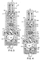
- FIG. 3 shows second piston 80 moving downwardly to increase the volume of area 105 as fluid is displaced from chamber 90 to area 105.
- Downward movement of piston 80 results in an increase in the output pressure corresponding to curve B1 of Figure 6.
- the increased output pressure (P out ) provided to the wheel cylinders of the wheel brakes will cause an increase in deceleration of the vehicle such that ball 110 moves up inclined surface 102 (see Figure 4) and permits closure of poppet valve means 99.
- the closure of the poppet valve means 99 prevents any fluid communication through passage 85 so that pressurized fluid is trapped within chamber 90 and prevents any further downward movement of second piston 80.
- Differential area piston 30 will continue to move downwardly as a result of the increased input pressure until seat 55 again approaches poppet 84 ( Figure 4) and establishes the high level break point B for a loaded vehicle. Restriction of fluid flow through valve seat 55 by poppet 84 results in the pressure curve B2 in Figure 6.
- chamber 90 is replenished by lip seal .86, with minimal restriction.
- the proportioning valve of the present invention does not require a bypass because in a split braking circuit having a master cylinder utilizing two of the proportioning valve assemblies, or in an axle-axle split system with one proportioning valve assembly, an inherent bypass is provided. If the one of the branches of the split circuit should fail, then there would be less deceleration of the vehicle and the poppet valve of the operative branch would stay open so that higher brake fluid pressure received from the master cylinder can be communicated to the associated brake cylinders. Thus, in case of failure, higher brake pressures can be communicated to the associated brake wheel cylinders to effect braking of the vehicle, and likewise for a system with a single proportioning valve assembly.
- Curve B2 represents also the inherent bypass function characteristic for an unloaded vehicle, while break point C and curve C1 represent the bypass characteristic for a loaded vehicle. Also, by providing for greater travel of the second piston than for the differential area piston, curve « D " may be obtained.
- the present invention provides for high pressure damping required in case of a spike application of the brakes.
- the seal 56 closes opening 73 and the suddenly increasing and high input pressure results in a net upward force on second piston 80 so that piston 80 remains in the position illustrated in the Figure 1 while differential area piston 30 moves downwardly to restrict seat 55 and restrict braking pressure communicated through outlet 31. Because the amount of fluid to area 105 is controlled, the overshoot tendency which may occur when a « spike application of the brakes occurs, is restricted.
- FIG. 5 there is illustrated an alternative embodiment 130 of the proportioning valve assembly of the present invention. Where applicable, like components will be referred to by the same numerals utilizing in reference to the preferred embodiment.
- the housing 12 is enclosed by a threaded cap 11 and contains a stepped bore 25 having therein the following same components as previously illustrated : inlet 14; outlet 16; differentiat area piston 30; through opening 31 ; seals 40 ; collar 26 ; retainer 50 ; radial openings 52 ; interior opening 54 ; seat 55 ; seals 56 and 57 ; poppet 84 ; piston extension 82 ; enlarged diameter portion 88 ; spring 75 collar 87; opening 73 ; stationary retainer 70 flange 71 ; seal 42 ; reduced diameter section 72 ; area 105; chamber 90 ; spring 92; seal 86; passage 85 ; poppet valve seat 100; ball 110 poppet valve means 99; and spring 98.
- the second piston 80 has a cavity 115 which receives therein poppet valve means 99 that is biased downwardly by spring 98 into engagement with a pivotable portion 122 of the pivotable mounting member 120.
- Pivotable mounting member 120 includes a plurality of fingers 124 which surround and couple thereto ball 110.
- the second piston 80 includes inward radial projections 116 which trap the pivotal projection 122 for engagement with poppet valve means 99.
- Member 120 provides a pendulum suspending ball 110 within chamber 90.
- Second piston 80 includes passages 117 which permit fluid to flow through opening 73, passage 85, poppet valve means 99, and into chamber 90.
- the proportioning valve assembly 130 provides a pendulum suspended ball 110 for operating poppet valve means 99 as a function of the deceleration of the vehicle.
- Proportioning valve assembly 130 operates in the same manner as described for the preferred embodiment, and produces the output curve characteristics illustrated in Figure 6.
- increase fluid pressure is communicated from the master cylinder (not shown) to inlet 14, the increased pressure is communicated freely through radial openings 52 to interior opening 54, through opening 73 to area 105, and through passages 117 and 85 past poppet valve means 99 to chamber 90.
- the increased pressure causes differential area piston 30 to move downwardly toward poppet 84.
- the seal 56 is brought into engagement with opening 73 to close the opening and prevent the increased fluid pressure from communicating with the area 105.
- poppet valve means 99 remains open and permits the second piston 80 to move downwardly which displaces fluid from chamber 90 through and past poppet valve means 99, passages 85 and 117, to area 105. This permits poppet 84 to be retracted away from seat 55 and allow higher output pressures to be communicated in accordance with curve B1 of Figure 6.
- the poppet valve spring 98 serves the multiple functions of retaining poppet valve means 99 in an open mode during low acceleration, and determining the deceleration at which the pendulum or member 120 will be able to close poppet valve means 99 in response to deceleration of the vehicle.
Landscapes
- Engineering & Computer Science (AREA)
- Transportation (AREA)
- Mechanical Engineering (AREA)
- Hydraulic Control Valves For Brake Systems (AREA)
Claims (14)
Applications Claiming Priority (2)
| Application Number | Priority Date | Filing Date | Title |
|---|---|---|---|
| US06/799,219 US4718734A (en) | 1985-11-18 | 1985-11-18 | Deceleration and pressure sensitive proportioning valve |
| US799219 | 1985-11-18 |
Publications (2)
| Publication Number | Publication Date |
|---|---|
| EP0223054A1 EP0223054A1 (de) | 1987-05-27 |
| EP0223054B1 true EP0223054B1 (de) | 1990-03-07 |
Family
ID=25175335
Family Applications (1)
| Application Number | Title | Priority Date | Filing Date |
|---|---|---|---|
| EP86114117A Expired EP0223054B1 (de) | 1985-11-18 | 1986-10-11 | Von Verzögerung- und Druck abhängiges Bremsventil |
Country Status (7)
| Country | Link |
|---|---|
| US (1) | US4718734A (de) |
| EP (1) | EP0223054B1 (de) |
| JP (1) | JPS62120252A (de) |
| BR (1) | BR8606010A (de) |
| CA (1) | CA1287856C (de) |
| DE (1) | DE3669286D1 (de) |
| ES (1) | ES2013590B3 (de) |
Families Citing this family (5)
| Publication number | Priority date | Publication date | Assignee | Title |
|---|---|---|---|---|
| DE3709991C2 (de) * | 1987-03-26 | 1994-08-11 | Teves Gmbh Alfred | Druckregeleinrichtung für druckmittelbetätigte Kraftfahrzeug-Bremssysteme |
| FR2660269B1 (fr) * | 1990-03-29 | 1992-06-12 | Bendix Europ Services Tech | Compensateur de freinage a valve additionnelle. |
| DE4010546A1 (de) * | 1990-04-02 | 1991-10-10 | Teves Gmbh Alfred | Bremsdrucksteuereinrichtung fuer kraftfahrzeuge |
| DE4127044A1 (de) * | 1990-09-19 | 1992-04-09 | Teves Gmbh Alfred | Lagerung fuer eine traegheitskugel eines verzoegerungsabhaengigen bremskraftreglers |
| DE102016213031A1 (de) * | 2016-07-18 | 2018-01-18 | Ford Global Technologies, Llc | Verfahren zum ruckfreien Stoppen eines Kraftfahrzeugs |
Family Cites Families (9)
| Publication number | Priority date | Publication date | Assignee | Title |
|---|---|---|---|---|
| GB1079505A (en) * | 1963-07-31 | 1967-08-16 | Girling Ltd | Improvements relating to vehicle brakes |
| US4047765A (en) * | 1974-07-03 | 1977-09-13 | Tex-Trans, Inc. | Hydraulic power transmission and braking system for vehicles |
| JPS5284365A (en) * | 1975-12-30 | 1977-07-13 | Aisin Seiki Co Ltd | Liquid pressure control system |
| US4196937A (en) * | 1978-02-03 | 1980-04-08 | Wagner Electric Corporation | Load sensing control valve |
| DE2814431A1 (de) * | 1978-04-04 | 1979-10-18 | Teves Gmbh Alfred | Verzoegerungsabhaengiger bremskraftregler |
| DE2814414A1 (de) * | 1978-04-04 | 1979-10-18 | Teves Gmbh Alfred | Bremskraftregler fuer zweikreisbremsanlagen |
| DE3222730A1 (de) * | 1981-09-30 | 1983-12-22 | Alfred Teves Gmbh, 6000 Frankfurt | Bremsdrucksteuerventil fuer eine kraftfahrzeugbremsanlage |
| DE3238132A1 (de) * | 1982-10-14 | 1984-04-19 | Lucas Industries P.L.C., Birmingham, West Midlands | Bremskraftregler fuer eine hydraulische fahrzeugbremsanlage |
| US4595243A (en) * | 1984-09-10 | 1986-06-17 | Allied Corporation | Deceleration and pressure sensitive proportioning valve |
-
1985
- 1985-11-18 US US06/799,219 patent/US4718734A/en not_active Expired - Fee Related
-
1986
- 1986-10-11 ES ES86114117T patent/ES2013590B3/es not_active Expired - Lifetime
- 1986-10-11 EP EP86114117A patent/EP0223054B1/de not_active Expired
- 1986-10-11 DE DE8686114117T patent/DE3669286D1/de not_active Expired - Lifetime
- 1986-10-21 CA CA000521040A patent/CA1287856C/en not_active Expired
- 1986-11-18 BR BR8606010A patent/BR8606010A/pt not_active IP Right Cessation
- 1986-11-18 JP JP61273067A patent/JPS62120252A/ja active Pending
Also Published As
| Publication number | Publication date |
|---|---|
| JPS62120252A (ja) | 1987-06-01 |
| EP0223054A1 (de) | 1987-05-27 |
| ES2013590B3 (es) | 1990-05-16 |
| US4718734A (en) | 1988-01-12 |
| CA1287856C (en) | 1991-08-20 |
| DE3669286D1 (de) | 1990-04-12 |
| BR8606010A (pt) | 1987-09-15 |
Similar Documents
| Publication | Publication Date | Title |
|---|---|---|
| JPH0311089Y2 (de) | ||
| EP0175089B1 (de) | Bremsdruck- und verzögerungsabhängiges Proportionierventil | |
| EP0223054B1 (de) | Von Verzögerung- und Druck abhängiges Bremsventil | |
| US4191210A (en) | Apparatus for braking systems incorporating a pressure-control device for antiskid control | |
| US4155603A (en) | Anti-skid vehicle braking systems | |
| US4834467A (en) | Hydraulic brake booster with anti-skid master cylinder plunger stop bushing | |
| US4736989A (en) | Dual deceleration and pressure-sensitive proportioning valve | |
| CA1172297A (en) | Master cylinder | |
| US4679864A (en) | Deceleration and pressure sensitive propoptioning valve with low deceleration responsiveness | |
| US3980343A (en) | Load responsive proportioning valve | |
| AU618213B2 (en) | Primary pressure-balanced proportioning valve | |
| AU612941B2 (en) | Primary pressure-balanced proportioning valve | |
| CA1240714A (en) | Height sensing proportioning valve | |
| US4652058A (en) | Deceleration and pressure sensitive proportioning valve with high pressure damping | |
| US5346291A (en) | Fluid pressure control valve with valve member mounted on guide pin slidably carried by piston | |
| EP0196808A1 (de) | Hydraulisches Blockierschutzsystem für Kraftfahrzeuge | |
| US4498299A (en) | Valve assembly | |
| GB2097080A (en) | Deceleration-sensing pressure proportioning or limiting valve assembly for vehicle braking systems | |
| US4386807A (en) | Pressure regulating valve for hydraulic brake systems | |
| US4858999A (en) | Pressure control unit with locking device for dual circuit brake systems | |
| US5022715A (en) | Pressure control device for brake systems of automotive vehicles | |
| US4203630A (en) | Brake control units | |
| US4225192A (en) | Antiskid control valve | |
| US4929033A (en) | Primary and secondary pressure-balanced proportioning valve | |
| US5161863A (en) | Braking pressure control device for automotive vehicles |
Legal Events
| Date | Code | Title | Description |
|---|---|---|---|
| PUAI | Public reference made under article 153(3) epc to a published international application that has entered the european phase |
Free format text: ORIGINAL CODE: 0009012 |
|
| AK | Designated contracting states |
Kind code of ref document: A1 Designated state(s): DE ES FR GB IT |
|
| 17P | Request for examination filed |
Effective date: 19871012 |
|
| 17Q | First examination report despatched |
Effective date: 19890419 |
|
| RAP1 | Party data changed (applicant data changed or rights of an application transferred) |
Owner name: ALLIED SIGNAL INCORPORATED |
|
| RAP1 | Party data changed (applicant data changed or rights of an application transferred) |
Owner name: ALLIED-SIGNAL INC. (A DELAWARE CORPORATION) |
|
| GRAA | (expected) grant |
Free format text: ORIGINAL CODE: 0009210 |
|
| ITF | It: translation for a ep patent filed |
Owner name: ING. ZINI MARANESI & C. S.R.L. |
|
| AK | Designated contracting states |
Kind code of ref document: B1 Designated state(s): DE ES FR GB IT |
|
| ET | Fr: translation filed | ||
| REF | Corresponds to: |
Ref document number: 3669286 Country of ref document: DE Date of ref document: 19900412 |
|
| PLBE | No opposition filed within time limit |
Free format text: ORIGINAL CODE: 0009261 |
|
| STAA | Information on the status of an ep patent application or granted ep patent |
Free format text: STATUS: NO OPPOSITION FILED WITHIN TIME LIMIT |
|
| 26N | No opposition filed | ||
| ITTA | It: last paid annual fee | ||
| PGFP | Annual fee paid to national office [announced via postgrant information from national office to epo] |
Ref country code: GB Payment date: 19931001 Year of fee payment: 8 |
|
| PGFP | Annual fee paid to national office [announced via postgrant information from national office to epo] |
Ref country code: FR Payment date: 19931011 Year of fee payment: 8 Ref country code: DE Payment date: 19931011 Year of fee payment: 8 |
|
| PGFP | Annual fee paid to national office [announced via postgrant information from national office to epo] |
Ref country code: ES Payment date: 19931026 Year of fee payment: 8 |
|
| PG25 | Lapsed in a contracting state [announced via postgrant information from national office to epo] |
Ref country code: GB Effective date: 19941011 |
|
| PG25 | Lapsed in a contracting state [announced via postgrant information from national office to epo] |
Ref country code: ES Free format text: LAPSE BECAUSE OF EXPIRATION OF PROTECTION Effective date: 19941013 |
|
| GBPC | Gb: european patent ceased through non-payment of renewal fee |
Effective date: 19941011 |
|
| PG25 | Lapsed in a contracting state [announced via postgrant information from national office to epo] |
Ref country code: FR Effective date: 19950630 |
|
| PG25 | Lapsed in a contracting state [announced via postgrant information from national office to epo] |
Ref country code: DE Effective date: 19950701 |
|
| REG | Reference to a national code |
Ref country code: FR Ref legal event code: ST |
|
| REG | Reference to a national code |
Ref country code: ES Ref legal event code: FD2A Effective date: 19990601 |
|
| PG25 | Lapsed in a contracting state [announced via postgrant information from national office to epo] |
Ref country code: IT Free format text: LAPSE BECAUSE OF NON-PAYMENT OF DUE FEES;WARNING: LAPSES OF ITALIAN PATENTS WITH EFFECTIVE DATE BEFORE 2007 MAY HAVE OCCURRED AT ANY TIME BEFORE 2007. THE CORRECT EFFECTIVE DATE MAY BE DIFFERENT FROM THE ONE RECORDED. Effective date: 20051011 |