EP0221738A2 - Dispositif de placement et d'orientation de bouton - Google Patents
Dispositif de placement et d'orientation de bouton Download PDFInfo
- Publication number
- EP0221738A2 EP0221738A2 EP86308287A EP86308287A EP0221738A2 EP 0221738 A2 EP0221738 A2 EP 0221738A2 EP 86308287 A EP86308287 A EP 86308287A EP 86308287 A EP86308287 A EP 86308287A EP 0221738 A2 EP0221738 A2 EP 0221738A2
- Authority
- EP
- European Patent Office
- Prior art keywords
- button
- guide
- head
- fastener
- passageway
- Prior art date
- Legal status (The legal status is an assumption and is not a legal conclusion. Google has not performed a legal analysis and makes no representation as to the accuracy of the status listed.)
- Withdrawn
Links
Images


Classifications
-
- A—HUMAN NECESSITIES
- A44—HABERDASHERY; JEWELLERY
- A44B—BUTTONS, PINS, BUCKLES, SLIDE FASTENERS, OR THE LIKE
- A44B1/00—Buttons
-
- A—HUMAN NECESSITIES
- A41—WEARING APPAREL
- A41H—APPLIANCES OR METHODS FOR MAKING CLOTHES, e.g. FOR DRESS-MAKING OR FOR TAILORING, NOT OTHERWISE PROVIDED FOR
- A41H37/00—Machines, appliances or methods for setting fastener-elements on garments
- A41H37/10—Setting buttons
Definitions
- the present invention relates to a machine for attaching fasteners or buttons, such as clinch-type and snap-type buttons, each having a pair of claws, to a garment, and more particularly to an apparatus for placing such fasteners or buttons one at a time on a die in a predetermined direction or orientation.
- Machines for attaching fasteners, such as clinch-type and snap-type buttons, to a garment are known in which one button and its mating fastener part at a time are delivered from their respective chutes to a die and a punch, respectively, and are then clinched or joined together by the punch and die with the garment placed therebetween. If the button bears on its front side a design, mark, symbol or emblem indicative of a specified orientation or direction in which the button is to be placed on a garment, the button must be oriented in such direction before the button arrives at the die.
- Japanese Patent Laid-Open Publication (Kokai) 52-13943 discloses an apparatus for orienting buttons, each having a pair of claws projecting from a rear side of a disk-like button head and spaced from each other radially of the disk-like head.
- the prior apparatus includes a pair of guide blocks mounted in a travelling path of the buttons by means of compression springs and having a pair of confronting wave-shaped edges defining a labyrinth passageway of a varying width decreasing progressively toward the die.
- the button turns or rolls, until it is oriented in a predetermined orientation or direction, as the confronting wave-shaped edges slidingly and resiliently engage the two claws of the button.
- this known apparatus requires a relatively large number of structural members and is hence complex in construction and expensive to manufacture.
- the present invention seeks to provide an apparatus for placing fasteners or buttons one at a time onto a die in a predetermined orientation or direction, which apparatus is simple in construction and can be attached to a button attaching machine with ease.
- an apparatus for placing a fastener or button on a die in a predetermined orientation for attachment to a garment comprising an elongate guide table defining a substantially horizontal first guide channel having one end adapted to be disposed contiguous to the die for guiding the fastener or button therethrough onto the die, said first guide channel including a first claw guide passageway for guiding therethrough the two claws of the fastener or button so as to prevent the latter from turning with respect to said first claw guide passageway, and a first fastener-head or button-head guide passageway for guiding therethrough the head of the fastener or button; a chute defining a sloping second guide channel communicating at its lower end with the other end of said first guide channel for guiding the fastener or button therethrough into said first guide channel, said second guide channel including a second
- a button orienting and placing apparatus generally comprises an elongate guide table 4 defining a substantially horizontal first guide channel for guiding buttons A one at a time onto a die 1 disposed contiguous to one end of the guide table 4, a sloping chute 11 defining a sloping second guide channel for receiving from a reservoir (not shown) the buttons A in a row and for discharging out of the chute 11 the buttons A one at a time into the first guide channel, and a pusher mechanism (described below) mounted within the guide table 4 for pushing the button A in the first guide channel onto the die 1.
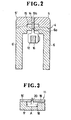
- the guide table 4 includes a pair of support bases 6, 6' of substantially inverted L-shaped cross section, and a pair of cover plates 5, 5' mounted on the support bases 6, 6', respectively.
- the two cover plates 5, 5' have their confronting inner edges spaced parallelly from each other by a predetermined distance, and each cover plate 5, 5' has a cutout in and along a lower corner of the inner edge.
- the confronting inner edges of the two cover plates 5, 5' define a claw guide passageway 14 for frictionally guiding therethrough a pair of claws of the individual button A such that the latter does not turn or roll, while the confronting cutouts of the two cover plates 5, 5' and the two support bases 6, 6' define a button-head guide pasageway 15 for guiding therethrough a disk-like head of the individual button A.
- the first guide channel is composed of the claw guide passageway 14 and the button-head guide passageway 15.
- the two support bases 6, 6' are laterally spaced so as to define between their confronting upper edges a longitudinal space 6a through which first and second pushers 12, 13 of the pusher mechanism are projectable into and retractable from the button-head guide passageway 15.
- the first and second pushers 12, 13 are also reciprocable along the longitudinal space 6a.
- one of the cover plates 5 has a reduced width at its one end portion adjacent to the chute 11, and an auxiliary cover plate 5a is fixedly mounted between the corresponding support base 6 and the cover plate 5.
- a first stop 7 is mounted between the support base 6 and the auxiliary cover plate 5a and is reciprocable toward and away from the chute 11, for a purpose described below.
- a second stop 9 is mounted on the other cover plate 5' substantially centrally between the chute 11 and the die 1 and is reciprocable toward and away from the opposite cover plate- 5, for a purpose described below.
- the first stop 7 is slidably received between the auxiliary cover plate 5a and the corresponding support base 6 and is movable in the directions of arrows in Figure 4 for receiving the button A from the chute 11 to temporarily prevent the button A from entering the first guide channel in the guide table 4.
- the first stop 7 is normally urged by a leaf spring 8 toward the other support base 6' so as to retractably project into the button-head guide passageway 15.
- the first stop 7 is in the form of a double-stage block including a small-thickness portion 24 and a large thickness portion 25.
- the small-thickness portion 24 has a horizontal top surface 24a which is flush with the top surface of the support base 6 as the first stop 7 is received in a recess (not numbered) in the top surface of the support base 6, while the large-thickness portion 25 has a groove 23.
- the small-thickness portion 24 projects into the longitudinal space 6a as the first stop 7 is mounted on the support base 6.
- the small-thickness portion 24 has also a slanting lower cam surface 26 at the die-side edge of its bottom.
- the first stop 7 has, at a step portion between the small-thickness and large-thickness portions 24, 25 , a concave surface 27 corresponding to the peripheral surface of the head of the button A.
- the small-thickness portion 24 has a side cam surface 28.
- the large-thickness portion 25 has on its bottom a downwardly directed projection 29 engageable with the side surface of the support base 6 so as to restrict the first stop 7 from entering the longitudinal space 6a too far under the bias of the leaf spring 8.
- the second stop 9 is slidably received in a recess (not shown) disposed substantially centrally of the other support base 6' and is movable in the directions of arrows in Figure 4 for temporarily stopping the button A again which is moved forwardly in the first guide channel of the guide table 4 after having been released from the first stop 7.
- the second stop 9 is normally urged by a spring 10 toward the support base 6 so as to retractably project into the longitudinal space 6a.
- each of the first and second pushers 12, 13 is adapted to push the head of the button A by its upper or front end 12a, 13a.
- the first pusher 12 pushes the button A from the first stop 7 to the second stop 9, and then the second pusher 13 pushes the button A from the second stop 9 to the die 1.
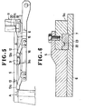
- the first and second pushers 12, 13 are mounted on a support bar 16 disposed below the first guide channel in the guide table 4, as shown in Figures 2 and 5.
- the support bar 16 is pivotally connected at one end to a non-illustrated drive via a non-illustrated toggle joint at a position downstream of a joint between the guide table 4 and the chute 11.
- Each of the first and second pushers 12, 13 extends obliquely upwardly from the support bar 16 through the longitudinal space 6a into the button-head and claw guide passageways 15, .14.
- the first and second pushers 12, 13 are disposed immediately upstream of the second stop 9 and the die 1, respectively, as shown in Figure 5.
- the first and second pushers 12, 13 are disposed immediately upstream of the first stop 7 and the second stop 9, respectively.
- the chute 11 includes an elongate chute base 17 of a generally u-shaped cross section, and a pair of covering plates 19, 19' covering the open side of the chute base 17.
- the two covering plates 19, 19' are laterally spaced in parallel from each other by a predetermined distance to define between their confronting inner edges a claw guide passageway 20 for frictionally guiding therethrough the two claws of the button A so as to prevent the latter from turning or rotating with respect to the claw guide passageway 20.
- the two covering plates 19 and 19' and the chute base 17 jointly define a button-head guide passageway 18 for guiding therethrough the head of the button A.
- the claw guide passageway 20 of the chute 11 has an arcuate lower end portion 20a curved progressively toward the die 1 and opening at its lower end to the claw guide passageway 14 of the guide table 4.
- the two claw guide passageways 20, 14 communicate with each other, while the two button-head guide passageways 18, 15 communicate with each other.
- the die-side wall of the chute base 17 has a cut-out 17a in its lower end portion so that the claws of the button A are smoothly guided along the arcuate lower end portion 20a of the claw guide passageway 20.
- a tangential line at the lower end of the arcuate lower end portion 20a of the claw guide passageway 20 is disposed preferably at an angle of 45° - 65° with respect to the claw guide passageway 14 of the guide table 4.
- the auxiliary cover plate 5a has on its bottom side a ridge 22 of a rectangular cross section which is slidably received in the groove 23 of the first stop 7 so that the first stop 7 can be moved so as to project into and retract from the longitudinal space 6a.
- the button A having been supplied from the non-illustrated reservoir is guided through the chute 11 toward the guide table 4, the head of the button A slides downwardly along the button-head guide passageway 18, and the two claws of the button A slide downwardly along the claw guide passageway 20 to reach the arcuate lower end portion 20a. While the two claws of the button A slide along the arcuate lower end portion 20a, the button A is turned through an angle equal to the central angle subtended by the arcuate lower end portion 20a. The button A then falls on the top horizontal surface 24a of the first stop 7 and is temporarily stopped as the head of the button A is received in the concave surface 27. As a result, the button A has been oriented in a predetermined direction.
- the support bar 16 is returned to its original or retracted position in which the first and second pushers 12, 13 are disposed immediately upstream of the first and second stops 7, 9, respectively. During that time the first and second pushers 12, 13 pass under the first and second stops 7, 9, respectively, slidingly contacting the respective cam surfaces 26, 9a. Thus the first and second pushers 12, 13 are returned to their original or retracted positions without being obstructed by the first and second stops 7, 9.
- the button A can be turned or rotated through a predetermined angle equal to the central angle subtended by the curved lower end portion 20a.
- the button A can be oriented in a predetermined direction easily and accurately with a small number of parts.
- buttons may be substituted for buttons.
Applications Claiming Priority (2)
| Application Number | Priority Date | Filing Date | Title |
|---|---|---|---|
| JP1985164846U JPH0630746Y2 (ja) | 1985-10-26 | 1985-10-26 | 釦用止め部品搬送装置 |
| JP164846/85 | 1985-10-26 |
Publications (2)
| Publication Number | Publication Date |
|---|---|
| EP0221738A2 true EP0221738A2 (fr) | 1987-05-13 |
| EP0221738A3 EP0221738A3 (fr) | 1987-10-14 |
Family
ID=15801033
Family Applications (1)
| Application Number | Title | Priority Date | Filing Date |
|---|---|---|---|
| EP86308287A Withdrawn EP0221738A3 (fr) | 1985-10-26 | 1986-10-24 | Dispositif de placement et d'orientation de bouton |
Country Status (6)
| Country | Link |
|---|---|
| US (1) | US4795072A (fr) |
| EP (1) | EP0221738A3 (fr) |
| JP (1) | JPH0630746Y2 (fr) |
| KR (1) | KR880001549Y1 (fr) |
| AU (1) | AU565497B2 (fr) |
| MY (1) | MY100825A (fr) |
Cited By (1)
| Publication number | Priority date | Publication date | Assignee | Title |
|---|---|---|---|---|
| EP2888966A4 (fr) * | 2012-08-24 | 2017-08-16 | YKK Corporation | Bouton et dispositif de transport d'élément de fixation de bouton |
Families Citing this family (3)
| Publication number | Priority date | Publication date | Assignee | Title |
|---|---|---|---|---|
| JPH02132621U (fr) * | 1989-04-04 | 1990-11-05 | ||
| JP2731061B2 (ja) * | 1991-12-25 | 1998-03-25 | ワイケイケイ株式会社 | 釦取付機の釦搬送ユニット |
| US7506789B2 (en) * | 2006-08-28 | 2009-03-24 | Arrow Fastener Company, Inc. | Continuous feed cap system |
Citations (2)
| Publication number | Priority date | Publication date | Assignee | Title |
|---|---|---|---|---|
| US3964661A (en) * | 1974-10-23 | 1976-06-22 | Textron, Inc. | Apparatus for attaching pronged and mating elements to articles |
| DE2926927A1 (de) * | 1979-07-04 | 1981-01-29 | Prym Werke William | Maschine zum ansetzen von oesenknoepfen |
Family Cites Families (13)
| Publication number | Priority date | Publication date | Assignee | Title |
|---|---|---|---|---|
| US3367550A (en) * | 1965-11-05 | 1968-02-06 | American Leather Specialties C | Automatic stud setting apparatus |
| JPS4726448U (fr) * | 1971-04-16 | 1972-11-25 | ||
| US3987950A (en) * | 1975-06-19 | 1976-10-26 | Textron, Inc. | Apparatus for orienting and attaching fasteners to an article |
| CA1038826A (fr) * | 1975-07-18 | 1978-09-19 | Textron Inc. | Appareil de fixation des elements a griffes et a couplages |
| JPS5227843A (en) * | 1975-08-28 | 1977-03-02 | Kanebo Ltd | Method of conveying bobbins of textile machine |
| US4019666A (en) * | 1975-11-10 | 1977-04-26 | Scovill Manufacturing Company | Fastener attaching machine having means for orienting caps, buttons, and the like |
| JPS5614246Y2 (fr) * | 1976-12-11 | 1981-04-03 | ||
| JPS5724751Y2 (fr) * | 1977-07-04 | 1982-05-28 | ||
| DE2856868A1 (de) * | 1978-12-30 | 1980-07-17 | Schaeffer Homberg Gmbh | Vorrichtung an einer ansetzmaschine |
| JPS598968Y2 (ja) * | 1981-04-22 | 1984-03-21 | ワイケイケイ株式会社 | 釦取付機における釦供給装置 |
| JPS5836148U (ja) * | 1981-09-03 | 1983-03-09 | シチズン時計株式会社 | 和文タイプライタの印字機構 |
| JPS6071627U (ja) * | 1983-10-18 | 1985-05-21 | 日本ノーシヨン工業株式会社 | 釦取付機の部品方向設定装置 |
| JPS6078826U (ja) * | 1983-11-04 | 1985-06-01 | 日本ノーシヨン工業株式会社 | 釦取付機における方向設定装置 |
-
1985
- 1985-10-26 JP JP1985164846U patent/JPH0630746Y2/ja not_active Expired - Lifetime
-
1986
- 1986-10-20 AU AU64216/86A patent/AU565497B2/en not_active Ceased
- 1986-10-22 KR KR2019860016078U patent/KR880001549Y1/ko not_active IP Right Cessation
- 1986-10-24 EP EP86308287A patent/EP0221738A3/fr not_active Withdrawn
- 1986-10-24 US US06/923,101 patent/US4795072A/en not_active Expired - Fee Related
- 1986-10-25 MY MYPI86000035A patent/MY100825A/en unknown
Patent Citations (2)
| Publication number | Priority date | Publication date | Assignee | Title |
|---|---|---|---|---|
| US3964661A (en) * | 1974-10-23 | 1976-06-22 | Textron, Inc. | Apparatus for attaching pronged and mating elements to articles |
| DE2926927A1 (de) * | 1979-07-04 | 1981-01-29 | Prym Werke William | Maschine zum ansetzen von oesenknoepfen |
Cited By (1)
| Publication number | Priority date | Publication date | Assignee | Title |
|---|---|---|---|---|
| EP2888966A4 (fr) * | 2012-08-24 | 2017-08-16 | YKK Corporation | Bouton et dispositif de transport d'élément de fixation de bouton |
Also Published As
| Publication number | Publication date |
|---|---|
| AU6421686A (en) | 1987-04-30 |
| AU565497B2 (en) | 1987-09-17 |
| KR880001549Y1 (ko) | 1988-05-04 |
| EP0221738A3 (fr) | 1987-10-14 |
| KR870006211U (ko) | 1987-05-06 |
| US4795072A (en) | 1989-01-03 |
| MY100825A (en) | 1991-03-15 |
| JPH0630746Y2 (ja) | 1994-08-17 |
| JPS6274614U (fr) | 1987-05-13 |
Similar Documents
| Publication | Publication Date | Title |
|---|---|---|
| US5031307A (en) | Apparatus for joining slider body and pull tab | |
| US4615473A (en) | Apparatus for assembling a pair of fastener elements | |
| US4332071A (en) | Method of and apparatus for attaching end stops to slide fastener stringer tapes | |
| EP0083103B1 (fr) | Méthode et appareil pour la mise en place de curseurs sur une chaîne continue de fermeture à glissière | |
| US4361946A (en) | Method of and apparatus for attaching sliders and top end stops for slide fasteners | |
| EP0138207B1 (fr) | Dispositif d'orientation et de placement d'un bouton | |
| US3781967A (en) | Buckle assembly machine and method | |
| CA1174454A (fr) | Dispositif retourneur-positionneur de bouton | |
| US4795072A (en) | Button orienting and placing apparatus | |
| EP0172546B1 (fr) | Procédé et appareil pour former un intervalle dépourvu d'éléments d'accouplement sur deux bandes continues de fermeture à glissière | |
| JPS60135005A (ja) | 隠しフアスナ用スライダ挿通装置 | |
| US4462154A (en) | Holder for use in assembling top end-stops to slide fasteners | |
| US4974305A (en) | Method of attaching fastener elements to fastener tape | |
| EP0222543B1 (fr) | Dispositif d'alimentation de boutons pour machine à fixer les boutons | |
| EP0058882B1 (fr) | Appareil pour fermer des sections exemptes d'éléments d'accouplement dans une chaîne continue de fermeture à glissière | |
| EP0260592B1 (fr) | Dispositif d'alimentation en éléments de fermeture pour machine à assembler lesdits éléments | |
| CA1242569A (fr) | Porte-boite a pince coulissante | |
| EP0303215B1 (fr) | Appareil pour fixer des butées d'extrémité supérieure sur une chaîne de fermetures à glissière | |
| US7100487B2 (en) | Punch device for creating a guide notch in a polymeric fastener attached to a plastic package | |
| US3789488A (en) | Assembly machine for a seal | |
| EP0257492A2 (fr) | Dispositif d'alimentation en éléments de fermeture pour une machine à assembler lesdits éléments | |
| GB2152865A (en) | Button orienting and placing apparatus | |
| EP0171743A1 (fr) | Appareil de montage et de finition d'une fermeture à glissière |
Legal Events
| Date | Code | Title | Description |
|---|---|---|---|
| PUAI | Public reference made under article 153(3) epc to a published international application that has entered the european phase |
Free format text: ORIGINAL CODE: 0009012 |
|
| AK | Designated contracting states |
Kind code of ref document: A2 Designated state(s): DE FR GB IT |
|
| PUAL | Search report despatched |
Free format text: ORIGINAL CODE: 0009013 |
|
| AK | Designated contracting states |
Kind code of ref document: A3 Designated state(s): DE FR GB IT |
|
| 17P | Request for examination filed |
Effective date: 19880119 |
|
| 17Q | First examination report despatched |
Effective date: 19880418 |
|
| STAA | Information on the status of an ep patent application or granted ep patent |
Free format text: STATUS: THE APPLICATION HAS BEEN WITHDRAWN |
|
| 18W | Application withdrawn |
Withdrawal date: 19880816 |
|
| RIN1 | Information on inventor provided before grant (corrected) |
Inventor name: SODENO, TOSHIAKI |