EP0219657B1 - Zusammengesetzte Vorrichtung zur Wärmeabteilung mit abwechselnd gewandten Rippen versehenen Stiften für einen von oben nach unten verlaufenden Strom - Google Patents
Zusammengesetzte Vorrichtung zur Wärmeabteilung mit abwechselnd gewandten Rippen versehenen Stiften für einen von oben nach unten verlaufenden Strom Download PDFInfo
- Publication number
- EP0219657B1 EP0219657B1 EP86111959A EP86111959A EP0219657B1 EP 0219657 B1 EP0219657 B1 EP 0219657B1 EP 86111959 A EP86111959 A EP 86111959A EP 86111959 A EP86111959 A EP 86111959A EP 0219657 B1 EP0219657 B1 EP 0219657B1
- Authority
- EP
- European Patent Office
- Prior art keywords
- pin
- wings
- base
- heat transfer
- composite
- Prior art date
- Legal status (The legal status is an assumption and is not a legal conclusion. Google has not performed a legal analysis and makes no representation as to the accuracy of the status listed.)
- Expired
Links
- 239000002131 composite material Substances 0.000 title claims description 52
- 239000012530 fluid Substances 0.000 claims description 20
- XLYOFNOQVPJJNP-UHFFFAOYSA-N water Substances O XLYOFNOQVPJJNP-UHFFFAOYSA-N 0.000 claims description 6
- 238000011144 upstream manufacturing Methods 0.000 claims description 4
- 238000005266 casting Methods 0.000 claims description 2
- 239000004020 conductor Substances 0.000 claims 1
- 238000000926 separation method Methods 0.000 claims 1
- 239000002826 coolant Substances 0.000 description 16
- 238000001816 cooling Methods 0.000 description 5
- 239000002184 metal Substances 0.000 description 5
- 230000000694 effects Effects 0.000 description 4
- 239000004065 semiconductor Substances 0.000 description 4
- 238000004519 manufacturing process Methods 0.000 description 3
- 238000010276 construction Methods 0.000 description 2
- 239000000919 ceramic Substances 0.000 description 1
- 230000001186 cumulative effect Effects 0.000 description 1
- 230000004907 flux Effects 0.000 description 1
- 230000006872 improvement Effects 0.000 description 1
- 238000005555 metalworking Methods 0.000 description 1
- 238000000034 method Methods 0.000 description 1
- 238000012986 modification Methods 0.000 description 1
- 230000004048 modification Effects 0.000 description 1
- 230000000630 rising effect Effects 0.000 description 1
- 238000005476 soldering Methods 0.000 description 1
Images

Classifications
-
- F—MECHANICAL ENGINEERING; LIGHTING; HEATING; WEAPONS; BLASTING
- F28—HEAT EXCHANGE IN GENERAL
- F28F—DETAILS OF HEAT-EXCHANGE AND HEAT-TRANSFER APPARATUS, OF GENERAL APPLICATION
- F28F13/00—Arrangements for modifying heat-transfer, e.g. increasing, decreasing
- F28F13/06—Arrangements for modifying heat-transfer, e.g. increasing, decreasing by affecting the pattern of flow of the heat-exchange media
- F28F13/12—Arrangements for modifying heat-transfer, e.g. increasing, decreasing by affecting the pattern of flow of the heat-exchange media by creating turbulence, e.g. by stirring, by increasing the force of circulation
-
- F—MECHANICAL ENGINEERING; LIGHTING; HEATING; WEAPONS; BLASTING
- F28—HEAT EXCHANGE IN GENERAL
- F28F—DETAILS OF HEAT-EXCHANGE AND HEAT-TRANSFER APPARATUS, OF GENERAL APPLICATION
- F28F3/00—Plate-like or laminated elements; Assemblies of plate-like or laminated elements
- F28F3/02—Elements or assemblies thereof with means for increasing heat-transfer area, e.g. with fins, with recesses, with corrugations
- F28F3/022—Elements or assemblies thereof with means for increasing heat-transfer area, e.g. with fins, with recesses, with corrugations the means being wires or pins
Definitions
- This invention relates to a device for transferring heat from a heat source such as a circuit component to a heat sink such as a stream of air or other fluid.
- this invention is an improvement in the heat transfer device described in the publication "Heat Sink” by R.C. Chu and U.P. Hwang in the IBM Technical Disclosure Bulletin, Vol. 17, No. 12, May 1975, pp. 3656-7.
- the published heat transfer device of Chu and Hwang has a base and an array of heat conducting pins that are mounted in a row and column array on the base.
- a coolant such as chilled air is directed through the array of pins and heat is transferred from the pins to the coolant.
- the coolant flows across the surface of the base, between the pins in a direction that will arbitrarily be called the column direction.
- the pins are given extended surface elements that will be called "wings”.
- the wings extend at least generally in the direction of coolant flow and give the composite pin fins a more streamlined shape.
- the base is a relatively thin metal plate that is in thermal contact with a heat producing component.
- the base has a planar surface and a rectangular perimeter.
- the base can alternatively be formed by a heat producing component itself, the surface can be cylindrical or spherical or any other shape that is adaptable to supporting the pins, and the perimeter can have any desired shape. It will be convenient to visualize the device oriented with its base in a horizontal plane and with the pin supporting surface facing upward, but the device can be given any orientation. The general case will usually be apparent without specific reference to these alternatives.
- the pins are cone shaped (the circular cross section of the cone is proportional to the heat flux) and the wings are shaped like parallelograms with two edges parallel to the side of the cone and two edges parallel to the base. Combining these parallelograms with the triangular cross section of the conical pin gives a trapezoidal shape to the pin and its wings when they are viewed along a row of the array.
- An object of this invention is to provide a new and improved heat transfer device having composite pin fins that produce an up-down or corrugated flow in the coolant flowing across the base. This corrugated flow mixes the heated coolant close to the base with cooler fluid flowing higher above the base and thereby improves the heat transfer from the composite pin fins.
- the heat transfer device of the invention is defined in claim 1.
- the surface of the wings produces an inherent drag on the flow of the coolant. Except for this drag, the coolant would, in a simplified analysis, generally flow evenly past the wings (but with some turbulence caused by the composite pin fins and by temperature differences in the fluid stream). The drag tends to slow the fluid, and the effect is cumulative along the horizontal length of the flow path. Thus, for a composite pin fin pointed up (like Chu and Hwang) the drag is greatest near the base and is least near the top. Conversely, for a composite pin fin pointing down the drag is greatest at the top and least near the base. Because the composite pin fins are pointed alternately up and down, the coolant stream encounters alternately higher and lower drag.
- the lines of coolant flow tend to bend toward the horizontally narrower end of the trapezoidal wings after passing the upstream edge of the wing and while flowing alongside a composite pin fin and they tend to bend the other way after passing the downstream edge of the wing and while flowing in the gap between consecutive composite pin fins.
- the drag of the composite pin fins tends to make the fluid pile up and thereby tends to divert the fluid toward the short parallel side of the trapezoid.
- Another object of the invention is to provide a composite pin fin device that is practical for manufacture and for use in cooling semiconductor circuit components. This feature of the invention will be illustrated by specific examples of pin and wing constructions.
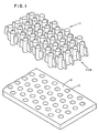
- FIG. 1 is an isometric view of the base and composite pin fins of the heat transfer device of this invention.
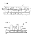
- FIG. 2 is a side view of the heat transfer device with arrows showing the flow of a coolant along a column of composite pin fins.
- FIG. 3 is a view similar to FIG. 2 and shows the relative dimensions of the composite pin fin components.
- FIG. 4 is a perspective showing an assembled composite pin fin and separately showing a pin and a wing structure that is crimped to the pin to form the assembled composite pin fin.
- FIG. 5 is a perspective showing a pin and one wing soldered to the pin and the other wing in a disassembled position before being soldered to the pin.
- FIG. 1 shows a base 10, and composite pin fins 11 with the pins removed from the base.
- a composite pin fin has a pin 12 and wings 14 attached to the pin, and the base has holes 13 that receive the ends of the pins.
- the pins are mounted on the base in a row and column array.
- An arrow shows the direction of coolant flow along columns of the composite pin fins.
- a shroud 15, shown in FIG. 2 is arranged to confine the fluid to flow through the array of composite pin fins. The shroud is spaced suitably above the tops of the composite pin fins so that heat transfer occurs from the upward facing surfaces of the composite pin fins.
- a semiconductor circuit package that is called a thermal conduction module has a ceramic chip carrier that is mounted on a circuit board, chips mounted on the carrier, a metal hat structure mounted over the chip carrier, and a cold plate attached to the hat.
- the hat carries metal pistons that are held against the chips by springs and conduct heat from a chip to the hat.
- the cold plate is a generally flat metal structure that has internal passages for chilled water. The passages are in the shape of a series of U turns between an inlet and an outlet. Heat is transferred to the water through the walls of the passages and through fins located in the passages. For this application the height of the composite pin fins is a few millimeters.
- FIG. 2 shows three composite pin fins 11a, 11b, 11c mounted along one column of base 10.
- FIG. 2 also shows shroud 15.
- the effect of the composite pin fin on the coolant flow will be described in terms of the general shape of the composite pin fins without regard to the physical structure of the pin and the wings, and the composite pin fins are shown in outline as trapezoids 16a, 16b, 16c.
- the trapezoids are identical except that trapezoids 16a and 16c point up and trapezoid 16b points down.
- Each trapezoid is divided symmetrically by a dashed line 17 indicating the axis of the pin.
- the wings have a longer parallel edge 18 and a shorter parallel edge 19 and two non-parallel edges 21 and 23. Since the wings are split symmetrically by the pin, each half-wing is also trapezoidal. From a more general standpoint, the wings are wider in the direction of coolant flow near longer parallel edge 18 and are narrower in the direction of coolant flow near shorter parallel edge 19, and they have non-parallel edges 21 and 23 across the direction of fluid flow.
- This general description of the wing shape includes for example a triangle and a half circle.
- the simple geometric trapezoid has advantages in manufacture as will be explained in the description of FIGS. 5 and 6, and it is preferred from the standpoint of the up-down flow. It also provides a large wing surface area for heat transfer, as will be apparent from the description of FIGS. 2 and 3.
- arrows 26 and 27 show a smooth flow past the wings and represent a simplified condition that would exist if this drag is not included in the analysis.
- the area between wings is an area of no drag in this analysis. Lines 26 and 27 are broken into segments to show where the lines of drag are equal or unequal in length.
- lines 26 and 27 have equal lengths of contact along the surfaces of the wings over the span of a number of composite pin fins. Consequently they have substantially equal lengths of drag and no drag over a column of composite pin fins. It can be seen that one flow line 26 or 27 encounters low drag while the other flow line encounters high drag. The flow lines are bent from the areas of high drag toward the areas of low drag, and the resulting up-down flow is represented by a sinusoid 28.
- FIG. 3 shows composite pin fins 11a and 11b with dimensions for the fins.
- the dimensions are in the range of dimensions that would be chosen for the conventional composite pin fin device of Chu and Hwang.
- the dimensions are in terms of the diameter of the pin which is designated "D".
- the long parallel edges 18u, 18d are each one to two diameters.
- the shorter parallel edge 19 (19u, 19d, plus the pin diameter) is between 2 to 3 2/3 diameters. Stated differently, each short edge 19u or 19d is about 1/2 to 2/3 the horizontal width of the long edge 18u or 18d, not counting the pin width.
- the pins are shorter (about two diameters) for good heat transfer fluids such as water and are higher (about 5 diameters) for poorer heat transfer fluids such as fluorocarbons. Note that the range of values for the dimensions may be limited when one of these dimensions has been specified.
- the preferred spacing between columns is about 2 to 4 diameters.
- the preferred spacing between rows is also about 2 to 4 diameters, but the row and column spacings are not necessarily the same.
- FIG. 1 The composite pin fin shown in FIG. 1 is formed as a unitary structure, preferably by a casting process.
- FIG. 4 shows a cone 31 of a thin metal that is crimped so as to grip pin 12 and to form wings 14u and 14d.
- FIG. 5 shows a pin 36 and wings 38, 39 that are assembled by soldering the wings in vertical grooves 40 in the pin. Note that the pins have portions 43, 44 that extend equally beyond the longer parallel edge 18 and the shorter parallel edge 19.
- the base has holes 13 shown in FIG. that receive these extending portions.
- the thickness of the fins can be tapered from the pin to the non parallel edges 21 and 23, as in Chu and Hwang, or they can have an essentially uniform thickness as in FIG. 1.
- the edges 21 and 23 can be rounded as in FIG. 4 or they can be blunt as in FIG. 1.
- the pins can be mounted on the base in any suitable pattern.
- the pattern of FIG. 1 is similar to FIG. 1 of the Chu and Hwang publication, where it is called a "staggered" arrangement.
- FIG. 2 of the Chu and Hwang publication shows an alternative "in-line” arrangement that can also be used with this invention.
- a composite pin fin is located at the intersection of each row and column.
- Other symmetrical patterns of composite pin fins will be apparent.
- the rows and columns can be given a non-uniform spacing.
- the parallel edges 18, 19 of the wings have been parallel to the columns of the pin locations, but in some applications it will be useful to turn the wings at a small angle to the column direction, up to about 35 degrees.
- the fins in one row can all be turned to the right and the pins in the next row turned to the left in a repeating pattern that produces a horizontally corrugated flow pattern.
- the term "column” means a straight or curving line connecting pins that have their wings about parallel to this connecting line or within about thirty-five degrees off the line.
- the pattern of pin spacing and the angle of the wings will be chosen to provide good heat transfer for a particular application.
- the location of the composite pin fins can be chosen to compensate for the effect that the coolant is heated as it flows through the fins. These factors can also be chosen to provide more or less cooling for different parts of the base, for example to provide more cooling near higher powered semiconductor chips and less cooling near lower powered semiconductor chips.
- the wings of the composite pin fins are turned to follow the U shape at the ends of the channel segments to keep the water flowing throughout the channel.
- the wings are turned to superimpose a horizontally corrugated flow on the U turn pattern.
Landscapes
- Engineering & Computer Science (AREA)
- Physics & Mathematics (AREA)
- Thermal Sciences (AREA)
- Mechanical Engineering (AREA)
- General Engineering & Computer Science (AREA)
- Cooling Or The Like Of Semiconductors Or Solid State Devices (AREA)
- Gloves (AREA)
- Power Steering Mechanism (AREA)
- Encapsulation Of And Coatings For Semiconductor Or Solid State Devices (AREA)
Claims (10)
- Vorrichtung zum Übertragen von Wärme mit zusammengesetzten Stiftrippen (11), die aufweist:
eine Basis (10), die durch ein Fluid gekühlt oder erwärmt werden soll, das durch eine Oberfläche der Basis gelenkt wird,
Stifte (12, 36) eines wärmeleitenden Materials, die auf der Oberfläche der Basis (10) entlang von Zeilen in Richtung für eine Fluidströmung angebracht sind,
Flügel (14, 38, 39), die an den Stiften befestigt sind und sich im allgemeinen in die stromaufwärts- und stromabwärts gelegenen Richtungen der Fluidströmung erstrecken, wobei die Flügel in Kombination (11) mit dem zugeordneten Stift im wesentlichen eine Trapezform beim Betrachten entlang der Oberfläche der Basis unter rechten Winkeln zu der Richtung einer Fluidströmung aufweisen, die Trapezform eine kurze Parallelseite (19) und eine lange Parallelseite (18) aufweist, die im wesentlichen parallel zu der Basis (10) liegen, und zwei nicht-parallele Seiten (21, 23) aufweist,
eine Abdeckung (15), die sich über den zusammengesetzten Stiftrippen (11) an ihren oberen Enden oder von der Basis (10) fernliegenden Enden erstreckt,
bei welcher
die zusammengesetzten Stiftrippen (11) entlang der Richtung einer Fluidströmung mit den kurzen Parallelseiten abwechselnd zu der Basis nahe und von der Basis entfernt ausgerichtet sind und wobei die nahen nicht-parallelen Seiten von Flügeln aufeinanderfolgender zusammengestzter Stiftrippen beabstandet sind,
wodurch die Fluidströmung durch den Rücktrieb von der Oberfläche der Flügel verlangsamt wird, welche sich zu der langen Parallelseite (18) der Flügel (14) näher als zu der kurzen Parallelseite (19) befinden und die Fluidströmung an den Flügeln vorbei folglich in Richtung der kurzen Parallelseite abgelenkt wird und eine auf und ab wellende Strömung für eine verbesserte Wärmeübertragung erzeugt wird. - Vorrichtung zum Übertragen von Wärme nach Anspruch 1, bei welcher die Basis (10) ein getrennter Bauteil ist, der zum Anbringen auf eine Wärmesenke oder eine Wärmequelle ausgebildet ist.
- Vorrichtung zum Übertragen von Wärme nach Anspruch 1 oder 2, bei welcher der Stift (12) um eine transversale Mittelebene symmetrisch ist, wodurch der Stift im wesentlichen dieselben Wärmeübertragungsmerkmale und dieselbe Impedanz für die Fluidströmung in jede Richtung der Stiftrippe (14) liefert.
- Vorrichtung nach Anspruch 3, bei welcher der Stift (12) zylindrisch ist und die Flügel (14) von einem abgestumpften konischen Element (31) gebildet sind, das an den Stift geklemmt ist.
- Vorrichtung nach Anspruch 3, bei welcher der Stift (36) zylindrisch ist und die Flügel von trapezförmigen Elementen (38, 39) gebildet sind, die an den Stift (36) gelötet sind.
- Vorrichtung nach Anspruch 3, bei welcher der Stift und seine Flügel eine durch Gießen ausgebildete einstückige Struktur (11) aufweisen.
- Vorrichtung zum Übertragen von Wärme nach irgendeinem der vorgehenden Ansprüche, bei welcher die Breite der langen Seite (18) eines stromaufwärts- oder stromabwärts gelegenen Flügels ungefähr einem bis zwei Stift-Durchmessern (D) gleich ist und die Trennung zwischen nahen nicht-parallelen Seiten (21, 23) aufeinanderfolgender Stiftrippen ungefähr der Hälfte eines Stift-Durchmessers gleich ist.
- Vorrichtung nach irgendeinem der vorgehenden Ansprüche, bei welcher die Stifte in gleichbeabstandeten Reihen und gleich beabstandeten Kolonnen auf der Basis (10) angebracht sind, wobei die Kolonnen um ungefähr zwei bis vier Durchmesser des Stiftes beabstandet sind.
- Vorrichtung nach irgendeinem der vorgehenden Ansprüche, bei welcher die Flügel aus der Zeilenrichtung um bis zu ungefähr 35 Grad gedreht sind, wobei die Flügel in jeder Reihe in dieselbe Richtung gedreht sind und die Flügel in aufeinanderfolgenden Reihen in entgegensetzte Richtungen gedreht sind, um eine sich horizontal wellende Strömung zu erzeugen.
- Vorrichtung nach irgendeinem der vorgehenden Ansprüche, die bei einer Kühlplatte für ein Schaltungsgehäuse ausgeführt ist, wobei die Kühlplatte innere Druchläufe für Kühlwasser von einem Einlaß zu einem Aus laß aufweist, die zusammengesetzten Stiftrippen einige Millimeter hoch sind und in den inneren Durchläufen angeordnet sind.
Applications Claiming Priority (2)
| Application Number | Priority Date | Filing Date | Title |
|---|---|---|---|
| US06/787,868 US4638858A (en) | 1985-10-16 | 1985-10-16 | Composite heat transfer device with pins having wings alternately oriented for up-down flow |
| US787868 | 1985-10-16 |
Publications (3)
| Publication Number | Publication Date |
|---|---|
| EP0219657A2 EP0219657A2 (de) | 1987-04-29 |
| EP0219657A3 EP0219657A3 (en) | 1989-02-15 |
| EP0219657B1 true EP0219657B1 (de) | 1991-05-15 |
Family
ID=25142765
Family Applications (1)
| Application Number | Title | Priority Date | Filing Date |
|---|---|---|---|
| EP86111959A Expired EP0219657B1 (de) | 1985-10-16 | 1986-08-29 | Zusammengesetzte Vorrichtung zur Wärmeabteilung mit abwechselnd gewandten Rippen versehenen Stiften für einen von oben nach unten verlaufenden Strom |
Country Status (4)
| Country | Link |
|---|---|
| US (1) | US4638858A (de) |
| EP (1) | EP0219657B1 (de) |
| JP (1) | JPS6294795A (de) |
| DE (1) | DE3679272D1 (de) |
Families Citing this family (36)
| Publication number | Priority date | Publication date | Assignee | Title |
|---|---|---|---|---|
| US4997034A (en) * | 1987-12-23 | 1991-03-05 | Minnesota Mining And Manufacturing Company | Heat exchanger |
| JPH0760107B2 (ja) * | 1989-07-11 | 1995-06-28 | 三菱電機株式会社 | 熱式流量センサの信号処理方法 |
| GB2236841B (en) * | 1989-08-09 | 1993-09-01 | James Wing Ho Wong | Heat exchangers |
| US5107798A (en) * | 1991-04-08 | 1992-04-28 | Sage Of America Co. | Composite studs, pulp mill recovery boiler including composite studs and method for protecting boiler tubes |
| US5304845A (en) * | 1991-04-09 | 1994-04-19 | Digital Equipment Corporation | Apparatus for an air impingement heat sink using secondary flow generators |
| US5158136A (en) * | 1991-11-12 | 1992-10-27 | At&T Laboratories | Pin fin heat sink including flow enhancement |
| JP3236137B2 (ja) * | 1993-07-30 | 2001-12-10 | 富士通株式会社 | 半導体素子冷却装置 |
| US5435384A (en) * | 1994-07-20 | 1995-07-25 | Wu; Chung | Heat dissipating plate |
| JPH08128793A (ja) * | 1994-10-28 | 1996-05-21 | Toshiba Corp | 内部フィン付伝熱管とその製造方法 |
| US5829514A (en) * | 1997-10-29 | 1998-11-03 | Eastman Kodak Company | Bonded cast, pin-finned heat sink and method of manufacture |
| US7479456B2 (en) * | 2004-08-26 | 2009-01-20 | Applied Materials, Inc. | Gasless high voltage high contact force wafer contact-cooling electrostatic chuck |
| US6803652B2 (en) * | 2001-05-30 | 2004-10-12 | Intel Corporation | Heat dissipation device having a load centering mechanism |
| DE10134187B4 (de) * | 2001-07-13 | 2006-09-14 | Semikron Elektronik Gmbh & Co. Kg | Kühleinrichtung für Halbleitermodule |
| US6817405B2 (en) * | 2002-06-03 | 2004-11-16 | International Business Machines Corporation | Apparatus having forced fluid cooling and pin-fin heat sink |
| US20040027781A1 (en) * | 2002-08-12 | 2004-02-12 | Hiroji Hanawa | Low loss RF bias electrode for a plasma reactor with enhanced wafer edge RF coupling and highly efficient wafer cooling |
| US6867978B2 (en) * | 2002-10-08 | 2005-03-15 | Intel Corporation | Integrated heat spreader package for heat transfer and for bond line thickness control and process of making |
| US20040200608A1 (en) * | 2003-04-11 | 2004-10-14 | Baldassarre Gregg J. | Plate fins with vanes for redirecting airflow |
| DE10333177A1 (de) * | 2003-07-22 | 2005-02-24 | Modine Manufacturing Co., Racine | Strömungskanal für einen Wärmeaustauscher |
| US20050063160A1 (en) * | 2003-09-23 | 2005-03-24 | Richard Ma | Heat-dissipating plate module |
| US7593230B2 (en) * | 2005-05-05 | 2009-09-22 | Sensys Medical, Inc. | Apparatus for absorbing and dissipating excess heat generated by a system |
| US20070121299A1 (en) * | 2005-11-30 | 2007-05-31 | International Business Machines Corporation | Heat transfer apparatus, cooled electronic module and methods of fabrication thereof employing thermally conductive composite fins |
| US20070215335A1 (en) * | 2006-03-14 | 2007-09-20 | Chun-Chi Chen | Heat sink |
| US20080112134A1 (en) * | 2006-11-09 | 2008-05-15 | Brandon Rubenstein | Dust accumulation resistant heat sink |
| WO2010110833A2 (en) * | 2008-12-31 | 2010-09-30 | Frontline Aerospace, Inc. | Recuperator for gas turbine engines |
| JP4835807B2 (ja) * | 2009-05-22 | 2011-12-14 | トヨタ自動車株式会社 | 熱交換器及びその製造方法 |
| US20110056669A1 (en) * | 2009-09-04 | 2011-03-10 | Raytheon Company | Heat Transfer Device |
| JP5770519B2 (ja) * | 2011-04-20 | 2015-08-26 | 株式会社日本自動車部品総合研究所 | 冷却フィン構造 |
| GB2502572A (en) * | 2012-05-30 | 2013-12-04 | Kraft Foods R & D Inc | Mould with optimised heat transfer properties |
| US10048019B2 (en) * | 2014-12-22 | 2018-08-14 | Hamilton Sundstrand Corporation | Pins for heat exchangers |
| DE102016208919A1 (de) * | 2016-05-24 | 2017-11-30 | Robert Bosch Gmbh | Kühlkörper zur Kühlung elektronischer Bauelemente |
| DE102016222587A1 (de) * | 2016-11-16 | 2018-05-17 | Fraunhofer-Gesellschaft zur Förderung der angewandten Forschung e.V. | Wärmetauscherstruktur und Verfahren zu deren Herstellung und Verwendung |
| US10907480B2 (en) * | 2018-09-28 | 2021-02-02 | Raytheon Technologies Corporation | Ribbed pin fins |
| US10490482B1 (en) * | 2018-12-05 | 2019-11-26 | Toyota Motor Engineering & Manufacturing North America, Inc. | Cooling devices including jet cooling with an intermediate mesh and methods for using the same |
| USD942403S1 (en) | 2019-10-24 | 2022-02-01 | Wolfspeed, Inc. | Power module having pin fins |
| AT522955B1 (de) * | 2020-01-27 | 2021-04-15 | Gerald Poellmann Mag | Wärmeableitungsvorrichtung |
| JP7428538B2 (ja) * | 2020-02-27 | 2024-02-06 | 三菱重工業株式会社 | 熱交換コア |
Family Cites Families (4)
| Publication number | Priority date | Publication date | Assignee | Title |
|---|---|---|---|---|
| SU661230A2 (ru) * | 1977-01-18 | 1979-05-05 | Предприятие П/Я В-8348 | Радиатор дл охлаждени полупроводниковых приборов |
| GB2085234A (en) * | 1980-10-08 | 1982-04-21 | Clarion Co Ltd | Radiating device for power amplifier |
| US4542784A (en) * | 1982-04-01 | 1985-09-24 | Planning Research Corporation | Retention and cooling of plug-in electronic modules in a high shock and vibration environment |
| US4567505A (en) * | 1983-10-27 | 1986-01-28 | The Board Of Trustees Of The Leland Stanford Junior University | Heat sink and method of attaching heat sink to a semiconductor integrated circuit and the like |
-
1985
- 1985-10-16 US US06/787,868 patent/US4638858A/en not_active Expired - Fee Related
-
1986
- 1986-08-29 EP EP86111959A patent/EP0219657B1/de not_active Expired
- 1986-08-29 DE DE8686111959T patent/DE3679272D1/de not_active Expired - Lifetime
- 1986-09-08 JP JP61209799A patent/JPS6294795A/ja active Granted
Also Published As
| Publication number | Publication date |
|---|---|
| EP0219657A3 (en) | 1989-02-15 |
| DE3679272D1 (de) | 1991-06-20 |
| JPH0315118B2 (de) | 1991-02-28 |
| US4638858A (en) | 1987-01-27 |
| EP0219657A2 (de) | 1987-04-29 |
| JPS6294795A (ja) | 1987-05-01 |
Similar Documents
| Publication | Publication Date | Title |
|---|---|---|
| EP0219657B1 (de) | Zusammengesetzte Vorrichtung zur Wärmeabteilung mit abwechselnd gewandten Rippen versehenen Stiften für einen von oben nach unten verlaufenden Strom | |
| US6173758B1 (en) | Pin fin heat sink and pin fin arrangement therein | |
| US4614227A (en) | Cooling body for the liquid cooling of high-power semiconductor components | |
| KR950014051B1 (ko) | 흐름이 향상된 핀 돌기 열 싱크 | |
| US5318112A (en) | Finned-duct heat exchanger | |
| US4449581A (en) | Heat exchanger fin element with dog-bone type pattern of corrugations | |
| KR910003071B1 (ko) | 열교환기 | |
| US11448466B2 (en) | Cross-flow heat exchanger | |
| US4574868A (en) | Flow directing element for heat exchanger | |
| KR100197718B1 (ko) | 공기조화기의 열교환기 | |
| KR920007299B1 (ko) | 전열휜 | |
| EP0086559A2 (de) | Wärmetauscher | |
| KR0182555B1 (ko) | 공기조화기의 열교환기 | |
| US4821795A (en) | Undulated heat exchanger fin | |
| KR0133026Y1 (ko) | 공기조화기의 열교환기 | |
| JPH11337284A (ja) | 熱交換器 | |
| JPS616592A (ja) | フイン付熱交換器 | |
| KR100189134B1 (ko) | 핀형 열교환기 | |
| KR0182542B1 (ko) | 공기조화기의 열교환기 | |
| KR100629283B1 (ko) | 열교환기 핀 | |
| JPS6361892A (ja) | 自動車用熱交換器 | |
| KR100256403B1 (ko) | 공기조화기의 열교환기 | |
| RU2037988C1 (ru) | Штыревой радиатор | |
| KR100261690B1 (ko) | 공기조화기의 열교환기 | |
| KR200152095Y1 (ko) | 공기조화기의 열교환기 |
Legal Events
| Date | Code | Title | Description |
|---|---|---|---|
| PUAI | Public reference made under article 153(3) epc to a published international application that has entered the european phase |
Free format text: ORIGINAL CODE: 0009012 |
|
| AK | Designated contracting states |
Kind code of ref document: A2 Designated state(s): DE FR GB |
|
| 17P | Request for examination filed |
Effective date: 19870821 |
|
| PUAL | Search report despatched |
Free format text: ORIGINAL CODE: 0009013 |
|
| AK | Designated contracting states |
Kind code of ref document: A3 Designated state(s): DE FR GB |
|
| 17Q | First examination report despatched |
Effective date: 19900817 |
|
| GRAA | (expected) grant |
Free format text: ORIGINAL CODE: 0009210 |
|
| AK | Designated contracting states |
Kind code of ref document: B1 Designated state(s): DE FR GB |
|
| REF | Corresponds to: |
Ref document number: 3679272 Country of ref document: DE Date of ref document: 19910620 |
|
| ET | Fr: translation filed | ||
| PLBE | No opposition filed within time limit |
Free format text: ORIGINAL CODE: 0009261 |
|
| STAA | Information on the status of an ep patent application or granted ep patent |
Free format text: STATUS: NO OPPOSITION FILED WITHIN TIME LIMIT |
|
| 26N | No opposition filed | ||
| PGFP | Annual fee paid to national office [announced via postgrant information from national office to epo] |
Ref country code: GB Payment date: 19960724 Year of fee payment: 11 |
|
| PGFP | Annual fee paid to national office [announced via postgrant information from national office to epo] |
Ref country code: FR Payment date: 19960806 Year of fee payment: 11 |
|
| PGFP | Annual fee paid to national office [announced via postgrant information from national office to epo] |
Ref country code: DE Payment date: 19960828 Year of fee payment: 11 |
|
| PG25 | Lapsed in a contracting state [announced via postgrant information from national office to epo] |
Ref country code: GB Free format text: LAPSE BECAUSE OF NON-PAYMENT OF DUE FEES Effective date: 19970829 |
|
| GBPC | Gb: european patent ceased through non-payment of renewal fee |
Effective date: 19970829 |
|
| PG25 | Lapsed in a contracting state [announced via postgrant information from national office to epo] |
Ref country code: FR Free format text: LAPSE BECAUSE OF NON-PAYMENT OF DUE FEES Effective date: 19980430 |
|
| PG25 | Lapsed in a contracting state [announced via postgrant information from national office to epo] |
Ref country code: DE Free format text: LAPSE BECAUSE OF NON-PAYMENT OF DUE FEES Effective date: 19980501 |
|
| REG | Reference to a national code |
Ref country code: FR Ref legal event code: ST |