EP0219376B1 - Vorrichtung zur Werkzeugkühlung in einer Werkzeugmaschine - Google Patents
Vorrichtung zur Werkzeugkühlung in einer Werkzeugmaschine Download PDFInfo
- Publication number
- EP0219376B1 EP0219376B1 EP86401941A EP86401941A EP0219376B1 EP 0219376 B1 EP0219376 B1 EP 0219376B1 EP 86401941 A EP86401941 A EP 86401941A EP 86401941 A EP86401941 A EP 86401941A EP 0219376 B1 EP0219376 B1 EP 0219376B1
- Authority
- EP
- European Patent Office
- Prior art keywords
- tool
- machine
- nozzle
- supports
- workpiece
- Prior art date
- Legal status (The legal status is an assumption and is not a legal conclusion. Google has not performed a legal analysis and makes no representation as to the accuracy of the status listed.)
- Expired
Links
- 238000001816 cooling Methods 0.000 title description 3
- 239000012809 cooling fluid Substances 0.000 claims description 5
- 238000005553 drilling Methods 0.000 claims description 3
- 238000005507 spraying Methods 0.000 claims description 2
- 239000007921 spray Substances 0.000 claims 3
- 239000002826 coolant Substances 0.000 description 3
- 239000007788 liquid Substances 0.000 description 2
- 238000003801 milling Methods 0.000 description 2
- 239000003351 stiffener Substances 0.000 description 2
- 239000012530 fluid Substances 0.000 description 1
- 239000000463 material Substances 0.000 description 1
- 230000004048 modification Effects 0.000 description 1
- 238000012986 modification Methods 0.000 description 1
- 238000009966 trimming Methods 0.000 description 1
Images
Classifications
-
- B—PERFORMING OPERATIONS; TRANSPORTING
- B23—MACHINE TOOLS; METAL-WORKING NOT OTHERWISE PROVIDED FOR
- B23Q—DETAILS, COMPONENTS, OR ACCESSORIES FOR MACHINE TOOLS, e.g. ARRANGEMENTS FOR COPYING OR CONTROLLING; MACHINE TOOLS IN GENERAL CHARACTERISED BY THE CONSTRUCTION OF PARTICULAR DETAILS OR COMPONENTS; COMBINATIONS OR ASSOCIATIONS OF METAL-WORKING MACHINES, NOT DIRECTED TO A PARTICULAR RESULT
- B23Q3/00—Devices holding, supporting, or positioning work or tools, of a kind normally removable from the machine
- B23Q3/02—Devices holding, supporting, or positioning work or tools, of a kind normally removable from the machine for mounting on a work-table, tool-slide, or analogous part
- B23Q3/06—Work-clamping means
- B23Q3/069—Work-clamping means for pressing workpieces against a work-table
-
- B—PERFORMING OPERATIONS; TRANSPORTING
- B23—MACHINE TOOLS; METAL-WORKING NOT OTHERWISE PROVIDED FOR
- B23Q—DETAILS, COMPONENTS, OR ACCESSORIES FOR MACHINE TOOLS, e.g. ARRANGEMENTS FOR COPYING OR CONTROLLING; MACHINE TOOLS IN GENERAL CHARACTERISED BY THE CONSTRUCTION OF PARTICULAR DETAILS OR COMPONENTS; COMBINATIONS OR ASSOCIATIONS OF METAL-WORKING MACHINES, NOT DIRECTED TO A PARTICULAR RESULT
- B23Q11/00—Accessories fitted to machine tools for keeping tools or parts of the machine in good working condition or for cooling work; Safety devices specially combined with or arranged in, or specially adapted for use in connection with, machine tools
- B23Q11/0042—Devices for removing chips
- B23Q11/005—Devices for removing chips by blowing
Definitions
- the present invention relates generally to machine tools and it relates more particularly to the sprinkling of the tool, during work, with a cooling fluid.
- this watering does not pose any particular problem and is ensured by a hose fixed for example on the spindle, or on a fixed part of the machine. such as the frame, with at its outlet end a nozzle located at a fixed distance from the active part of the tool so that the coolant, usually a special liquid, is always sent to this same part of the tool while working, no problem.
- the nozzle d watering at a constant distance from the workpiece surface should be set in an intermediate position relative to the length of the tool and located at a fixed distance from the workpiece surface, so that the tool does not is not cooled rationally and efficiently, its part in contact with the part moving away from the nozzle as the working stroke progresses.
- this nozzle must also be located in an intermediate position relative to the length of the tool, such that it can penetrate into the workpiece from a sufficient distance without coming up against it before the end of the working stroke.
- FR-A 2 323 496 describes a machine tool with a rotary tool comprising a suction chamber open downwards for the passage of the tool and the wall of which surrounds the latter, a spring forcing the wall towards the workpiece and at least one nozzle disposed inside this chamber and adapted to be connected to an external source of pressurized fluid.
- This arrangement is suitable for use on a machine working either parallel or perpendicular to the surface of the workpiece and comprising a central vacuum and a central pressurization.
- Chip removal is necessary in the case of milling or trimming by removing a large amount of material, producing an even larger volume of chips.
- the invention therefore aims to provide a simple and inexpensive device for cooling the tool of a machine tool working only in the axial direction of the tool.
- the subject of the invention is to this end a device with a spraying nozzle for a rotary tool with a cooling fluid, adaptable to a machine tool, and comprising two telescopic supports, each of said supports comprising a first part intended to be mounted. on each side of the tool nose and parallel to the axis of this tool on the same mobile part of the machine as this tool, a second part mounted telescopically movable axially relative to the tool on said first part and carrying said sprinkler nozzle in the vicinity of the end of the tool and elastic means forcing said second part towards the workpiece, so that said sprinkler nozzle is located at a constant distance from the point to be machined from the workpiece the entire working stroke.
- said support is mounted on the tiller nose of the machine and has a length greater than that of said spindle and of the tool.
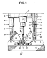
- FIG. 1 shows the spindle nose 1 of an automatic drilling machine comprising a spindle 2 and a mandrel 3 in which a drill 4 is fixed.
- end 5 of the drill is shown in contact with the surface of a work to be drilled, consisting of a plate 6 carrying a stiffener represented by an angle 7, at the instant preceding the start of work.
- the machine comprises a device for watering the drill 4, which comprises, in the embodiment shown, a circular fixing ring 8 fixedly mounted on the spindle nose 1 by any known means, not shown, such as screws.
- Crown 8 carries two telescopic supports each designated generally by the reference 9, fixed at two opposite points of its circumference and which extend downward parallel to the drill 4, on either side thereof, the assembly having the form of a stirrup.
- the supports 9 being identical, only one of them will be described.
- Each support 9 is formed by two tubes 10, 11 fitted telescopically one inside the other, the tube 10, in which the tube 11 slides, being fixed in the crown 8, for example by screwing.
- the tube 10 has in its wall a slot 14 extending longitudinally over a part of its length and in which is engaged a lug 15 projecting radially from the tube 11 in order to limit the telescopic stroke of the latter in the tube 10 and to immobilize it in rotation.
- a spring 16 bearing on the one hand on the end of the fixed rod 12 and on the other hand on the bottom of the blind bore 13, this spring urging the tube 11 in the extended position relative to the tube 10.
- the diameter of the spring 16 is equal to the inside diameter of the tube 10.
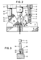
- the tube 11 has at its outer end parallel flats 17 on which is fixed a nozzle-carrying member 18, by means of lugs 19 integral with the latter, by bolts.
- the member 18 as a whole has a roughly triangular shape having a thickness roughly equal to the diameter of the tube 11 ( Figure 3) and has one side 21 oriented towards the drill, in the plane defined by it and the support 9, the arrangement being such that the member 18 has a lower angle 20 in the vicinity of the end 5 of the drill, the edge 21 being inclined upwards away from the latter.
- the nozzle holder member 18 has, in its thickness, a bore 22 parallel to its edge 21, at one end of which is fixed, at the lower angle 20, a nozzle 23 for sprinkling the drill, oriented towards its end 5 .
- a connector 24 for a coolant inlet pipe connected to a suitable power source (not shown).
- the nozzle 23 is removable and can be replaced by another one of different diameter depending on the desired liquid flow rate.
- a stud 25 projecting from the lower edge of the member 18, the arrangement being such that from the nose 1 of the spindle, the sum of the lengths of the tube 11, of the member 18 and of the stud 25, in the fully extended position of the tube 11, ie slightly greater than the sum of the lengths of the spindle 2, the mandrel 3 and the drill 4.
- the rod 12 can be omitted and the spring urging the tube 11 in extension can be placed directly in the tube 10, between the spindle nose 1 and the internal end of the tube 11 .
- the flat shape of the nozzle-carrying members 18 allows the device to pass along the stiffeners 7 and to drill holes adjacent to them, as shown in FIG. 3.
- the invention is not limited to the embodiment shown and described to which modifications can be made without departing from the scope of protection.
- the studs 25 can be replaced by appendages made from one piece with the members 18 which, themselves, can also have come from one piece with the tubes 11.
- the crown 8 can be mounted orientable on the spindle nose, its angular position being able to be controlled by a software program in the case of an automatic machine with electronic control.
- telescopic spring system of the tubes 10 and 11 of each support 9 can be replaced in a variant, not shown, by a servo system, hydraulic or other.
Landscapes
- Engineering & Computer Science (AREA)
- Mechanical Engineering (AREA)
- Drilling And Boring (AREA)
Claims (8)
Applications Claiming Priority (2)
| Application Number | Priority Date | Filing Date | Title |
|---|---|---|---|
| FR8513462 | 1985-09-11 | ||
| FR8513462A FR2586957B1 (fr) | 1985-09-11 | 1985-09-11 | Dispositif de buse d'arrosage pour le refroidissement de l'outil d'une machine-outil |
Publications (2)
| Publication Number | Publication Date |
|---|---|
| EP0219376A1 EP0219376A1 (de) | 1987-04-22 |
| EP0219376B1 true EP0219376B1 (de) | 1989-04-26 |
Family
ID=9322803
Family Applications (1)
| Application Number | Title | Priority Date | Filing Date |
|---|---|---|---|
| EP86401941A Expired EP0219376B1 (de) | 1985-09-11 | 1986-09-04 | Vorrichtung zur Werkzeugkühlung in einer Werkzeugmaschine |
Country Status (3)
| Country | Link |
|---|---|
| EP (1) | EP0219376B1 (de) |
| DE (1) | DE3662982D1 (de) |
| FR (1) | FR2586957B1 (de) |
Families Citing this family (5)
| Publication number | Priority date | Publication date | Assignee | Title |
|---|---|---|---|---|
| FR2656820A1 (fr) * | 1990-01-05 | 1991-07-12 | Pfalzgraf Sa Epb Emile | Ensemble porte-outils muni d'un dispositif de palpage. |
| US6715971B2 (en) * | 2001-04-09 | 2004-04-06 | Gary L. Curtis | Automated coolant delivery method and system for a machine tool |
| DE10346726A1 (de) * | 2003-10-08 | 2005-05-19 | Karl-Heinz Arnold Gmbh | Vorrichtung zum Zuführen eines Kühlschmierstoffstroms beim spanabhebenden Bearbeiten von Werkstücken |
| CN112548671A (zh) * | 2020-12-14 | 2021-03-26 | 南通云达信息技术有限公司 | 一种用于制造手机的机床刀头冷却器的自动调节装置 |
| CN115070079B (zh) * | 2022-07-18 | 2024-05-28 | 南通佳景健康科技股份有限公司 | 一种基于激光定位的水疗按摩池镂孔加工机器人 |
Family Cites Families (7)
| Publication number | Priority date | Publication date | Assignee | Title |
|---|---|---|---|---|
| US2420905A (en) * | 1943-05-18 | 1947-05-20 | American Smelting Refining | Drill sampling device |
| CH241054A (de) * | 1944-04-22 | 1946-02-15 | Landert Heinr | Schleifmaschine mit Flüssigkeitskühlung. |
| US3617141A (en) * | 1969-04-23 | 1971-11-02 | Ekstrom Carlson & Co | Tool turret |
| FR2114153A5 (de) * | 1970-11-18 | 1972-06-30 | Wilson Ets | |
| CH596946A5 (de) * | 1975-09-09 | 1978-03-31 | Infranor Sa | |
| NL7601588A (nl) * | 1975-02-28 | 1976-08-31 | Lechner Helmut | Op een boormachine of dergelijk gereedschap aanbrengbare inrichting voor het opvangen, respektievelijk afvoeren van bij het boren losgerakend materiaal. |
| JPS5859746A (ja) * | 1981-10-06 | 1983-04-08 | Sanshin Ind Co Ltd | 工作機械の集塵装置 |
-
1985
- 1985-09-11 FR FR8513462A patent/FR2586957B1/fr not_active Expired - Fee Related
-
1986
- 1986-09-04 EP EP86401941A patent/EP0219376B1/de not_active Expired
- 1986-09-04 DE DE8686401941T patent/DE3662982D1/de not_active Expired
Also Published As
| Publication number | Publication date |
|---|---|
| FR2586957B1 (fr) | 1992-10-23 |
| EP0219376A1 (de) | 1987-04-22 |
| DE3662982D1 (en) | 1989-06-01 |
| FR2586957A1 (fr) | 1987-03-13 |
Similar Documents
| Publication | Publication Date | Title |
|---|---|---|
| EP0918594B1 (de) | Vorrichtung zum entfernen von spänen des bearbeitungskopfs einer werkzeugmaschine | |
| FR2695341A1 (fr) | Dispositif pour la fourniture d'un fluide à un outil d'usinage. | |
| FR2627412A1 (fr) | Amelioration de douilles de serrage | |
| EP0219376B1 (de) | Vorrichtung zur Werkzeugkühlung in einer Werkzeugmaschine | |
| EP0588713B1 (de) | Fräs-, Planfräs- und Polier-Maschine für automatischen Werkzeugwechsel und entsprechende Vorrichtung | |
| FR2548074A1 (fr) | Capot de protection de la meule pour une rectifieuse plane | |
| FR2612438A1 (fr) | Machine-outil, notamment perceuse ou taraudeuse | |
| EP0245177B1 (de) | Vorrichtung zum Stützen eines Werkstückes zur Ermöglichung der Bearbeitung auf seiner fünften Fläche | |
| EP0436453A1 (de) | Werkzeugeinheit mit Fühler | |
| FR2481178A1 (fr) | Dispositif d'usinage de surfaces cylindriques pour une machine-outil a travailler des metaux par coupe | |
| FR2631880A1 (fr) | Groupe outil pour des machines a faconner le bois | |
| FR2467040A1 (fr) | Dispositif pour ebarber interieurement des tuyaux a soudure longitudinale | |
| EP0347513B1 (de) | Vorrichtung zum Positionieren und Blockieren auf dem Spindelkopf einer Werkzeugmaschine von verschiedenen Einrichtungen zur mechanischen Bearbeitung | |
| EP0000294B1 (de) | Rückzugvorrichtung des Werkzeuges an Werkzeugmaschinen | |
| EP0211128B1 (de) | Werkzeugsupport einer automatischen Drehmaschine mit Kühleinrichtung für diese Werkzeuge | |
| FR2490519A1 (fr) | Foret de percage, son procede de fabrication et son mode d'utilisation | |
| FR2595751A1 (fr) | Outil de carottage, notamment pour carottage a l'air | |
| WO1990011159A1 (fr) | Porte-outil et broche tournante rapide | |
| FR2561147A1 (fr) | Outil de percage avec alimentation en agent de refroidissement | |
| FR2488323A1 (fr) | Ajutage de forage par un jet de fluide et procede de forage | |
| FR2703280A1 (fr) | Procédé et dispositif de montage d'outillages. | |
| CH684577A5 (fr) | Elément de pulvérisation pour la lubrification lors d'usinage de métaux. | |
| EP1125661B1 (de) | Radialbohreinrichtung einer Drehmaschine | |
| CH647705A5 (fr) | Dispositif de relevage d'outil de percage pour perceuse electrique a main. | |
| FR2766752A1 (fr) | Machine pour l'affutage d'outils de coupe |
Legal Events
| Date | Code | Title | Description |
|---|---|---|---|
| PUAI | Public reference made under article 153(3) epc to a published international application that has entered the european phase |
Free format text: ORIGINAL CODE: 0009012 |
|
| 17P | Request for examination filed |
Effective date: 19860905 |
|
| AK | Designated contracting states |
Kind code of ref document: A1 Designated state(s): BE DE GB IT NL |
|
| 17Q | First examination report despatched |
Effective date: 19880325 |
|
| GRAA | (expected) grant |
Free format text: ORIGINAL CODE: 0009210 |
|
| AK | Designated contracting states |
Kind code of ref document: B1 Designated state(s): BE DE GB IT NL |
|
| ITF | It: translation for a ep patent filed | ||
| REF | Corresponds to: |
Ref document number: 3662982 Country of ref document: DE Date of ref document: 19890601 |
|
| GBT | Gb: translation of ep patent filed (gb section 77(6)(a)/1977) | ||
| PLBE | No opposition filed within time limit |
Free format text: ORIGINAL CODE: 0009261 |
|
| STAA | Information on the status of an ep patent application or granted ep patent |
Free format text: STATUS: NO OPPOSITION FILED WITHIN TIME LIMIT |
|
| 26N | No opposition filed | ||
| PGFP | Annual fee paid to national office [announced via postgrant information from national office to epo] |
Ref country code: GB Payment date: 19910830 Year of fee payment: 6 |
|
| PGFP | Annual fee paid to national office [announced via postgrant information from national office to epo] |
Ref country code: DE Payment date: 19910906 Year of fee payment: 6 |
|
| PGFP | Annual fee paid to national office [announced via postgrant information from national office to epo] |
Ref country code: BE Payment date: 19910927 Year of fee payment: 6 |
|
| ITTA | It: last paid annual fee | ||
| PGFP | Annual fee paid to national office [announced via postgrant information from national office to epo] |
Ref country code: NL Payment date: 19910930 Year of fee payment: 6 |
|
| PG25 | Lapsed in a contracting state [announced via postgrant information from national office to epo] |
Ref country code: GB Effective date: 19920904 |
|
| PG25 | Lapsed in a contracting state [announced via postgrant information from national office to epo] |
Ref country code: BE Effective date: 19920930 |
|
| BERE | Be: lapsed |
Owner name: AEROSPATIALE SOC. NATIONALE INDUSTRIELLE Effective date: 19920930 |
|
| PG25 | Lapsed in a contracting state [announced via postgrant information from national office to epo] |
Ref country code: NL Effective date: 19930401 |
|
| GBPC | Gb: european patent ceased through non-payment of renewal fee |
Effective date: 19920904 |
|
| NLV4 | Nl: lapsed or anulled due to non-payment of the annual fee | ||
| PG25 | Lapsed in a contracting state [announced via postgrant information from national office to epo] |
Ref country code: DE Effective date: 19930602 |
|
| PG25 | Lapsed in a contracting state [announced via postgrant information from national office to epo] |
Ref country code: IT Free format text: LAPSE BECAUSE OF NON-PAYMENT OF DUE FEES;WARNING: LAPSES OF ITALIAN PATENTS WITH EFFECTIVE DATE BEFORE 2007 MAY HAVE OCCURRED AT ANY TIME BEFORE 2007. THE CORRECT EFFECTIVE DATE MAY BE DIFFERENT FROM THE ONE RECORDED. Effective date: 20050904 |