EP0219239B1 - Geschwindigkeitsregler für einen Stromerzeuger eines Flugzeugs - Google Patents
Geschwindigkeitsregler für einen Stromerzeuger eines Flugzeugs Download PDFInfo
- Publication number
- EP0219239B1 EP0219239B1 EP86307263A EP86307263A EP0219239B1 EP 0219239 B1 EP0219239 B1 EP 0219239B1 EP 86307263 A EP86307263 A EP 86307263A EP 86307263 A EP86307263 A EP 86307263A EP 0219239 B1 EP0219239 B1 EP 0219239B1
- Authority
- EP
- European Patent Office
- Prior art keywords
- speed
- drive device
- control unit
- circuit
- control signal
- Prior art date
- Legal status (The legal status is an assumption and is not a legal conclusion. Google has not performed a legal analysis and makes no representation as to the accuracy of the status listed.)
- Expired
Links
- 239000007858 starting material Substances 0.000 description 15
- 230000035939 shock Effects 0.000 description 5
- 238000010586 diagram Methods 0.000 description 2
- 230000005540 biological transmission Effects 0.000 description 1
- 230000007423 decrease Effects 0.000 description 1
- 230000000694 effects Effects 0.000 description 1
- 230000005284 excitation Effects 0.000 description 1
- 238000007493 shaping process Methods 0.000 description 1
Images
Classifications
-
- F—MECHANICAL ENGINEERING; LIGHTING; HEATING; WEAPONS; BLASTING
- F02—COMBUSTION ENGINES; HOT-GAS OR COMBUSTION-PRODUCT ENGINE PLANTS
- F02N—STARTING OF COMBUSTION ENGINES; STARTING AIDS FOR SUCH ENGINES, NOT OTHERWISE PROVIDED FOR
- F02N11/00—Starting of engines by means of electric motors
- F02N11/04—Starting of engines by means of electric motors the motors being associated with current generators
-
- H—ELECTRICITY
- H02—GENERATION; CONVERSION OR DISTRIBUTION OF ELECTRIC POWER
- H02P—CONTROL OR REGULATION OF ELECTRIC MOTORS, ELECTRIC GENERATORS OR DYNAMO-ELECTRIC CONVERTERS; CONTROLLING TRANSFORMERS, REACTORS OR CHOKE COILS
- H02P29/00—Arrangements for regulating or controlling electric motors, appropriate for both AC and DC motors
- H02P29/0016—Control of angular speed of one shaft without controlling the prime mover
Definitions
- This invention relates to speed control units for aircraft electric generators. It is known, for example from U.S. Patent 4278928, to provide an electric generator arrangement for use in an aircraft.
- the generator arrangement includes a constant speed drive unit which provides a step up in speed and also includes a speed control which maintains the generator rotor at a constant speed over a wide range of input speeds. When the input speed is low the constant speed drive unit therefore has its highest output/input gear ratio.
- An input shaft of the constant speed drive unit is commonly coupled to a shaft of an engine of the aircraft through an auxiliary gearbox which also provides a connection for a starter for the engine. During engine starting, therefore, the engine starter is required to drive the generator arrangement in addition to the engine.
- the load imposed by the generator arrangement is a substantial proportion of the total load on the starter. Moreover, because of the initial low engine speed the constant speed drive unit would tend to move to its maximum gear ratio and impose an excessively high torque load on the starter.
- the engine starter must be sized to accommodate the maximum torque of the shock load, and this may impose an unacceptable weight and size penalty.
- a speed control unit for an aircraft electric generator comprising a continuously variable ratio drive device, means for sensing the speed of an output shaft of said device, and a control circuit for generating a control signal responsive to a difference between a sensed speed and a desired speed of said output shaft, said drive device being responsive to said control signal for varying the ratio of the input and output speeds of said drive device, to maintain said output speed constant, said control circuit including means for delaying application of said control signal to said drive device until said output shaft has reached a predetermined speed, is characterised in that said control circuit includes a circuit for increasing the rise time of said control signal after said predetermined speed has been reached.
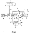
- a power take-off shaft 10 is drivingly coupled to a high pressure shaft of a gas turbine engine 11.
- An auxiliary gearbox 12 is driven by the shaft 10 and provides a drive to a generator arrangement 13 and to other auxiliary equipment (not shown) such as hydraulic pumps.
- a starter motor 14 for the engine 11 is permanently or selectively coupled to the engine 11 through the gearbox 12 and shaft 10.
- the motor 14 may be regarded as directly coupled to the shaft 10 and rotating at the same speed as the engine high pressure shaft.
- An input shaft 15 for the generator arrangement 13 is driven from the gearbox 12 and drives a constant speed drive device 20 of the type described in U.S. Patent 4278928, incorporated herein by reference.
- An output shaft 21 of the unit 20 drives a permanent magnet alternator 16 whose output is applied on a line 17 to provide excitation for a brushless main alternator 18 of a known type.
- the output of the main alternator 18 is provided on lines 19.
- the rotors of the alternators 16, 18 are coupled through an over-running clutch 22 which is such that drive may be applied from the device 20 to the alternator 18, but not in the reverse direction.
- the frequency of the output from the alternator 16 corresponds to the speed of the shaft 15, and therefore to the speed of the rotor of the main alternator 18, when the clutch 22 is not over-running.
- This speed signal is supplied on a line 23 to a control circuit 24 which provides a speed control signal on a line 25 to the constant speed drive device 20.
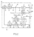
- the circuit 24 is shown in more detail in Figure 2 and includes a pulse-shaping circuit 30 responsive to the signals on line 23. Output pulses from the circuit 30 are supplied to frequency to voltage converters 32, 33 which provide, on respective lines 34, 35 voltage signals -V whose magnitude is negatively proportional to the frequency F of the speed signal on line 23.
- the signal on line 34 is applied through a resistor 39 to a summing junction 36.
- a reference voltage Vr which is proportional to the desired speed of the rotor of the alternator 18 provides another input to the summing junction 36, and a further input to the junction 36 is supplied from a ramp generator circuit 37 which, in the presence of a 28 volt biasing signal on a line 38 maintains an output signal which is equal in magnitude and opposite in sign to the voltage Vr.
- the junction 36 is connected through a resistor 40 to an amplifier 47.
- the output of the amplifier 47 is connected to the line 25 through relay contacts 48, the contacts 48 being ganged with contacts 49 between the 28 volt supply and the line 38, so that when the ramp generator 37 is biased to oppose the voltage Vr, the line 25 is also isolated from the control circuit 24.
- the speed signal -V on line 35 is applied to a detector circuit 50 which provides a high level signal if the signal frequency on line 23 falls below 620 Hz and a low level signal if this frequency rises above 640 Hz.
- the signal on line 35 is also applied to a further detector circuit 51 which provides a high level signal if the frequency on line 23 exceeds 1800 Hz and a low signal if that frequency falls below 1760 Hz.
- Signals from the detector circuits 50, 51 are applied to a NOR logic circuit 52 which is responsive to a high level signal from either of the circuits 50, 51 to de-energise an electro-magnetic actuator 53 for the contacts 48, 49 and allow them to move to the position shown in the drawing, in which no signal is applied on the line 25 to the drive device 20.
- a high level signal from the circuit 51 is indicative of an over-speed condition of the shaft 15, and hence of the alternator 18 and operates a latching circuit 54 to maintain the contacts 48, 49 in the operating position shown until a reset signal is applied on a line 55.
- a frequency of 640 Hz on the line 23 corresponds to a speed of 3850 RPM of the shaft 10.
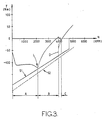
- Figure 3 shows a graph of torque T at the shaft 10 plotted against the speed N of that shaft. Negative values correspond to torque loads from the engine 11, gearbox 12 and generator arrangement 13, and positive values correspond to input torque from the engine 11. Negative torque values thus correspond to load on the starter 14 ( Figure 1).
- the portion A of the graph shows the torque load from initial starting to a point L at which the engine 11 lights.
- Increasing torque output from the engine 11 reduces the torque load over portion B, up to a speed of 3850 of the shaft 10.
- the relay 48, 49, 53 Figure 2 operates and the gear ratio of the drive 20 progressively increases over the ramp time C of the generator 37. Though the increasing gear ratio increases the torque load on the starter 14 this load increase is gradual and at the end of the ramp time C the torque from the engine 11 again increases to exceed the loads imposed on it.
- a dotted portion D of the graph shows the effect on torque load if the drive device 20 were suddenly allowed to assume control at 3850 RPM, without control by the ramp generator 37. It will be seen that a high torque load is suddenly applied, which would result in a shock load on the starter 14, gearbox 12 and shaft 10 and might cause the engine to stall at that point.
- the line S1 shows the torque/speed characteristics of a typical starter 14. With the ramp control of the present invention it is necessary only that the characteristic S1 should enclose the torque curve at the point L, since the load substantially decreases thereafter. In the absence of ramp control it will be seen that the starter 14 must have a torque characteristic at least as great as S2, and in practice substantially greater to avoid interruption by the shock load D. This latter condition would require a starter of considerably increased size and weight.
- Engine starters are commonly designed to cut out at ground idle speed of the engine, this speed being typically, as in the present example, 4700 RPM. It will be seen from Figure 3 that at this speed the torque supplied by the engine 11 is not itself sufficient to accommodate the shock load D, so that merely delaying operation of the drive device 20 until ground idle speed has been reached will not suffice.
Landscapes
- Engineering & Computer Science (AREA)
- Power Engineering (AREA)
- Chemical & Material Sciences (AREA)
- Combustion & Propulsion (AREA)
- Mechanical Engineering (AREA)
- General Engineering & Computer Science (AREA)
- Control Of Eletrric Generators (AREA)
- Control Of Velocity Or Acceleration (AREA)
- Control Of Vehicle Engines Or Engines For Specific Uses (AREA)
Claims (5)
Applications Claiming Priority (2)
| Application Number | Priority Date | Filing Date | Title |
|---|---|---|---|
| GB8525096 | 1985-10-11 | ||
| GB858525096A GB8525096D0 (en) | 1985-10-11 | 1985-10-11 | Speed control unit |
Publications (2)
| Publication Number | Publication Date |
|---|---|
| EP0219239A1 EP0219239A1 (de) | 1987-04-22 |
| EP0219239B1 true EP0219239B1 (de) | 1990-08-22 |
Family
ID=10586531
Family Applications (1)
| Application Number | Title | Priority Date | Filing Date |
|---|---|---|---|
| EP86307263A Expired EP0219239B1 (de) | 1985-10-11 | 1986-09-22 | Geschwindigkeitsregler für einen Stromerzeuger eines Flugzeugs |
Country Status (5)
| Country | Link |
|---|---|
| US (1) | US4733155A (de) |
| EP (1) | EP0219239B1 (de) |
| JP (1) | JPH0736719B2 (de) |
| DE (1) | DE3673598D1 (de) |
| GB (1) | GB8525096D0 (de) |
Families Citing this family (21)
| Publication number | Priority date | Publication date | Assignee | Title |
|---|---|---|---|---|
| US4908565A (en) * | 1987-02-18 | 1990-03-13 | Sundstrand Corporation | Power generating system |
| US5097163A (en) * | 1989-12-22 | 1992-03-17 | Sundstrand Corporation | Electrical power generating system having reduced conducted emissions in output power |
| US5136837A (en) * | 1990-03-06 | 1992-08-11 | General Electric Company | Aircraft engine starter integrated boundary bleed system |
| US5125597A (en) * | 1990-06-01 | 1992-06-30 | General Electric Company | Gas turbine engine powered aircraft environmental control system and boundary layer bleed with energy recovery system |
| US5114103A (en) * | 1990-08-27 | 1992-05-19 | General Electric Company | Aircraft engine electrically powered boundary layer bleed system |
| JP3440287B2 (ja) | 1999-12-01 | 2003-08-25 | 川崎重工業株式会社 | 航空機搭載発電機の定速駆動方法および定速駆動装置 |
| US6838778B1 (en) | 2002-05-24 | 2005-01-04 | Hamilton Sundstrand Corporation | Integrated starter generator drive having selective torque converter and constant speed transmission for aircraft having a constant frequency electrical system |
| US6838779B1 (en) * | 2002-06-24 | 2005-01-04 | Hamilton Sundstrand Corporation | Aircraft starter generator for variable frequency (vf) electrical system |
| US20050200349A1 (en) * | 2004-03-15 | 2005-09-15 | Brant Duke | Method and apparatus of determining gas turbine shaft speed |
| US7532969B2 (en) * | 2006-03-09 | 2009-05-12 | Pratt & Whitney Canada Corp. | Gas turbine speed detection |
| US20070265761A1 (en) * | 2006-05-11 | 2007-11-15 | Dooley Kevin A | Electric power generation system and method |
| US8169100B2 (en) * | 2008-01-30 | 2012-05-01 | Pratt & Whitney Canada Corp. | Torque transmission for an aircraft engine |
| US8267835B2 (en) | 2008-03-18 | 2012-09-18 | Briggs And Stratton Corporation | Generator set |
| US8845486B2 (en) * | 2008-03-18 | 2014-09-30 | Briggs & Stratton Corporation | Transmission for outdoor power equipment |
| FR2931456B1 (fr) * | 2008-05-26 | 2010-06-11 | Snecma | Aeronef a alimentation en energie hybride. |
| FR2952121B1 (fr) * | 2009-10-29 | 2011-12-23 | Snecma | Dispositif d'entrainement mecanique du corps haute pression d'un moteur d'avion |
| US20110314963A1 (en) * | 2010-06-28 | 2011-12-29 | Hamilton Sundstrand Corporation | Controllable constant speed gearbox |
| US8519555B2 (en) | 2010-11-29 | 2013-08-27 | Pratt & Whitney Canada Corp. | Combination low spool generator and ram air turbine generator |
| US9188105B2 (en) | 2011-04-19 | 2015-11-17 | Hamilton Sundstrand Corporation | Strut driveshaft for ram air turbine |
| DE102011112250A1 (de) * | 2011-09-02 | 2013-03-07 | Rolls-Royce Deutschland Ltd & Co Kg | Hilfsgerätegetriebeeinrichtung für ein Triebwerk |
| EP3885562B1 (de) * | 2018-11-19 | 2024-07-17 | Kawasaki Jukogyo Kabushiki Kaisha | Stromerzeugungsteuerungsvorrichtung für flugzeug |
Family Cites Families (9)
| Publication number | Priority date | Publication date | Assignee | Title |
|---|---|---|---|---|
| DE2739980A1 (de) * | 1976-09-08 | 1978-03-09 | Lucas Industries Ltd | Generatoranordnung |
| JPS5678400A (en) * | 1979-11-26 | 1981-06-27 | Fuji Electric Co Ltd | Initial exciting method of synchronous generator |
| AU543105B2 (en) * | 1980-03-19 | 1985-04-04 | Ogden Electronics Ltd. | Vehicle speed control |
| JPH0448158Y2 (de) * | 1980-04-18 | 1992-11-12 | ||
| US4439720A (en) * | 1981-01-23 | 1984-03-27 | Societe Aman | Units for generating constant-frequency alternating electric energy with substitute driving means |
| GB2093134B (en) * | 1981-02-12 | 1985-02-13 | Automotive Prod Co Ltd | Regulating fluid pressure in the control system of an automatic transmission |
| JPS57148595A (en) * | 1981-03-09 | 1982-09-13 | Shinko Electric Co Ltd | Main shaft drive generating apparatus |
| JPS6022499A (ja) * | 1983-07-19 | 1985-02-04 | Toyota Motor Corp | 内燃機関付車輛の発電装置 |
| US4572961A (en) * | 1984-04-18 | 1986-02-25 | The United States Of America As Represented By The Secretary Of The Air Force | Constant speed drive with compensation using differential gears |
-
1985
- 1985-10-11 GB GB858525096A patent/GB8525096D0/en active Pending
-
1986
- 1986-09-19 US US06/909,488 patent/US4733155A/en not_active Expired - Lifetime
- 1986-09-22 DE DE8686307263T patent/DE3673598D1/de not_active Expired - Lifetime
- 1986-09-22 EP EP86307263A patent/EP0219239B1/de not_active Expired
- 1986-09-29 JP JP61228500A patent/JPH0736719B2/ja not_active Expired - Fee Related
Also Published As
| Publication number | Publication date |
|---|---|
| GB8525096D0 (en) | 1985-11-13 |
| US4733155A (en) | 1988-03-22 |
| JPS62100200A (ja) | 1987-05-09 |
| JPH0736719B2 (ja) | 1995-04-19 |
| EP0219239A1 (de) | 1987-04-22 |
| DE3673598D1 (de) | 1990-09-27 |
Similar Documents
| Publication | Publication Date | Title |
|---|---|---|
| EP0219239B1 (de) | Geschwindigkeitsregler für einen Stromerzeuger eines Flugzeugs | |
| US4401938A (en) | Variable-speed drive for control of induction generators | |
| US4246531A (en) | Constant frequency variable rpm generator | |
| US4322668A (en) | Power control of a stalling motor | |
| US4743776A (en) | Starter-generator for engines | |
| CA2397649C (en) | Auxiliary electrical power generation system and method of operating same | |
| US5051670A (en) | Aircraft DC starter-generator torque controller | |
| SE467422B (sv) | Anordning foer att saekerstaella start av en foerbraenningsmotor | |
| US4942493A (en) | Method and apparatus for detecting prime mover start malfunction | |
| US4185203A (en) | Closed loop rotational speed control system for twin-shaft type gas turbine electric generator | |
| GB2484230A (en) | Method and system for controlling aircraft engine starter/generator | |
| EP0197209A1 (de) | Zweistufige elektrisches Antriebsystem | |
| US4488198A (en) | Protective circuit for clutchless parallel generating system | |
| EP0094686B1 (de) | Ladekontrolleinrichtung für Fahrzeug | |
| US5266836A (en) | Method and apparatus for operating a motor vehicle alternator | |
| US4870339A (en) | Variable-speed power generating system | |
| US3993912A (en) | Marine propulsion system | |
| US3973539A (en) | Fuel systems for engines | |
| US4139780A (en) | Multi-channel generator drive system | |
| US4510899A (en) | Electronic overspeed switch | |
| US4220868A (en) | Method of and system for controllably connecting load to generator | |
| GB1591258A (en) | Alternating current generating set | |
| JP2558671B2 (ja) | ガバナレス可変速水車発電装置の水車回転速度制限方法 | |
| SU1684114A2 (ru) | Электромеханическа двухпоточна трансмисси | |
| CA1205128A (en) | Self-starting single-phase synchronous motor |
Legal Events
| Date | Code | Title | Description |
|---|---|---|---|
| PUAI | Public reference made under article 153(3) epc to a published international application that has entered the european phase |
Free format text: ORIGINAL CODE: 0009012 |
|
| AK | Designated contracting states |
Kind code of ref document: A1 Designated state(s): DE FR GB IT SE |
|
| 17P | Request for examination filed |
Effective date: 19870923 |
|
| 17Q | First examination report despatched |
Effective date: 19890316 |
|
| GRAA | (expected) grant |
Free format text: ORIGINAL CODE: 0009210 |
|
| AK | Designated contracting states |
Kind code of ref document: B1 Designated state(s): DE FR GB IT SE |
|
| REF | Corresponds to: |
Ref document number: 3673598 Country of ref document: DE Date of ref document: 19900927 |
|
| ET | Fr: translation filed | ||
| ITF | It: translation for a ep patent filed | ||
| PLBE | No opposition filed within time limit |
Free format text: ORIGINAL CODE: 0009261 |
|
| STAA | Information on the status of an ep patent application or granted ep patent |
Free format text: STATUS: NO OPPOSITION FILED WITHIN TIME LIMIT |
|
| 26N | No opposition filed | ||
| ITTA | It: last paid annual fee | ||
| EAL | Se: european patent in force in sweden |
Ref document number: 86307263.3 |
|
| PGFP | Annual fee paid to national office [announced via postgrant information from national office to epo] |
Ref country code: SE Payment date: 19960917 Year of fee payment: 11 |
|
| PG25 | Lapsed in a contracting state [announced via postgrant information from national office to epo] |
Ref country code: SE Free format text: LAPSE BECAUSE OF NON-PAYMENT OF DUE FEES Effective date: 19970923 |
|
| EUG | Se: european patent has lapsed |
Ref document number: 86307263.3 |
|
| REG | Reference to a national code |
Ref country code: GB Ref legal event code: IF02 |
|
| PGFP | Annual fee paid to national office [announced via postgrant information from national office to epo] |
Ref country code: DE Payment date: 20020925 Year of fee payment: 17 |
|
| PGFP | Annual fee paid to national office [announced via postgrant information from national office to epo] |
Ref country code: FR Payment date: 20030909 Year of fee payment: 18 |
|
| PGFP | Annual fee paid to national office [announced via postgrant information from national office to epo] |
Ref country code: GB Payment date: 20030917 Year of fee payment: 18 |
|
| PG25 | Lapsed in a contracting state [announced via postgrant information from national office to epo] |
Ref country code: DE Free format text: LAPSE BECAUSE OF NON-PAYMENT OF DUE FEES Effective date: 20040401 |
|
| PG25 | Lapsed in a contracting state [announced via postgrant information from national office to epo] |
Ref country code: GB Free format text: LAPSE BECAUSE OF NON-PAYMENT OF DUE FEES Effective date: 20040922 |
|
| GBPC | Gb: european patent ceased through non-payment of renewal fee |
Effective date: 20040922 |
|
| PG25 | Lapsed in a contracting state [announced via postgrant information from national office to epo] |
Ref country code: FR Free format text: LAPSE BECAUSE OF NON-PAYMENT OF DUE FEES Effective date: 20050531 |
|
| REG | Reference to a national code |
Ref country code: FR Ref legal event code: ST |
|
| PG25 | Lapsed in a contracting state [announced via postgrant information from national office to epo] |
Ref country code: IT Free format text: LAPSE BECAUSE OF NON-PAYMENT OF DUE FEES;WARNING: LAPSES OF ITALIAN PATENTS WITH EFFECTIVE DATE BEFORE 2007 MAY HAVE OCCURRED AT ANY TIME BEFORE 2007. THE CORRECT EFFECTIVE DATE MAY BE DIFFERENT FROM THE ONE RECORDED. Effective date: 20050922 |