EP0219099A2 - Kühlsystem für eine Brennkraftmaschine - Google Patents
Kühlsystem für eine Brennkraftmaschine Download PDFInfo
- Publication number
- EP0219099A2 EP0219099A2 EP86114221A EP86114221A EP0219099A2 EP 0219099 A2 EP0219099 A2 EP 0219099A2 EP 86114221 A EP86114221 A EP 86114221A EP 86114221 A EP86114221 A EP 86114221A EP 0219099 A2 EP0219099 A2 EP 0219099A2
- Authority
- EP
- European Patent Office
- Prior art keywords
- coolant
- coolant jacket
- radiator
- reservoir
- jacket
- Prior art date
- Legal status (The legal status is an assumption and is not a legal conclusion. Google has not performed a legal analysis and makes no representation as to the accuracy of the status listed.)
- Granted
Links
- 238000001816 cooling Methods 0.000 title claims abstract description 35
- 238000002485 combustion reaction Methods 0.000 title claims description 19
- 239000002826 coolant Substances 0.000 claims abstract description 360
- 230000004044 response Effects 0.000 claims abstract description 11
- 239000007788 liquid Substances 0.000 claims description 69
- 238000000034 method Methods 0.000 claims description 15
- 238000009833 condensation Methods 0.000 claims description 11
- 230000005494 condensation Effects 0.000 claims description 11
- 238000000926 separation method Methods 0.000 claims description 8
- 230000004907 flux Effects 0.000 claims description 6
- 238000004891 communication Methods 0.000 claims description 4
- 239000012530 fluid Substances 0.000 claims description 4
- 238000007599 discharging Methods 0.000 claims description 2
- 238000005086 pumping Methods 0.000 claims description 2
- 238000013022 venting Methods 0.000 claims 5
- 238000009835 boiling Methods 0.000 description 15
- XLYOFNOQVPJJNP-UHFFFAOYSA-N water Substances O XLYOFNOQVPJJNP-UHFFFAOYSA-N 0.000 description 9
- QVGXLLKOCUKJST-UHFFFAOYSA-N atomic oxygen Chemical compound [O] QVGXLLKOCUKJST-UHFFFAOYSA-N 0.000 description 5
- 238000005260 corrosion Methods 0.000 description 5
- 230000000694 effects Effects 0.000 description 5
- 230000006698 induction Effects 0.000 description 5
- 239000001301 oxygen Substances 0.000 description 5
- 229910052760 oxygen Inorganic materials 0.000 description 5
- 230000005484 gravity Effects 0.000 description 4
- LYCAIKOWRPUZTN-UHFFFAOYSA-N Ethylene glycol Chemical compound OCCO LYCAIKOWRPUZTN-UHFFFAOYSA-N 0.000 description 3
- 239000000919 ceramic Substances 0.000 description 3
- 230000007797 corrosion Effects 0.000 description 3
- 239000000446 fuel Substances 0.000 description 3
- 230000001965 increasing effect Effects 0.000 description 3
- 230000002441 reversible effect Effects 0.000 description 3
- 230000008901 benefit Effects 0.000 description 2
- 239000003795 chemical substances by application Substances 0.000 description 2
- 238000010276 construction Methods 0.000 description 2
- 230000006378 damage Effects 0.000 description 2
- 230000006866 deterioration Effects 0.000 description 2
- 238000001704 evaporation Methods 0.000 description 2
- 230000008020 evaporation Effects 0.000 description 2
- 238000007654 immersion Methods 0.000 description 2
- 230000001939 inductive effect Effects 0.000 description 2
- 230000007257 malfunction Effects 0.000 description 2
- 238000013021 overheating Methods 0.000 description 2
- 230000002035 prolonged effect Effects 0.000 description 2
- 238000010926 purge Methods 0.000 description 2
- 238000007789 sealing Methods 0.000 description 2
- 230000003685 thermal hair damage Effects 0.000 description 2
- 238000012546 transfer Methods 0.000 description 2
- 108010053481 Antifreeze Proteins Proteins 0.000 description 1
- 208000005189 Embolism Diseases 0.000 description 1
- 235000014676 Phragmites communis Nutrition 0.000 description 1
- 206010035148 Plague Diseases 0.000 description 1
- 241000607479 Yersinia pestis Species 0.000 description 1
- 230000001133 acceleration Effects 0.000 description 1
- 230000002411 adverse Effects 0.000 description 1
- 230000002528 anti-freeze Effects 0.000 description 1
- 238000013459 approach Methods 0.000 description 1
- 229910010293 ceramic material Inorganic materials 0.000 description 1
- 238000011109 contamination Methods 0.000 description 1
- 230000007423 decrease Effects 0.000 description 1
- 238000006073 displacement reaction Methods 0.000 description 1
- 230000007613 environmental effect Effects 0.000 description 1
- 238000002474 experimental method Methods 0.000 description 1
- 239000007789 gas Substances 0.000 description 1
- 238000010438 heat treatment Methods 0.000 description 1
- 230000001771 impaired effect Effects 0.000 description 1
- 230000006872 improvement Effects 0.000 description 1
- 230000035515 penetration Effects 0.000 description 1
- 230000002265 prevention Effects 0.000 description 1
- 230000008569 process Effects 0.000 description 1
- 230000001737 promoting effect Effects 0.000 description 1
- 238000004537 pulping Methods 0.000 description 1
- 230000005855 radiation Effects 0.000 description 1
- 230000009467 reduction Effects 0.000 description 1
- 238000009877 rendering Methods 0.000 description 1
- 230000000717 retained effect Effects 0.000 description 1
- 238000005070 sampling Methods 0.000 description 1
- 238000009834 vaporization Methods 0.000 description 1
- 230000008016 vaporization Effects 0.000 description 1
Images


Classifications
-
- F—MECHANICAL ENGINEERING; LIGHTING; HEATING; WEAPONS; BLASTING
- F01—MACHINES OR ENGINES IN GENERAL; ENGINE PLANTS IN GENERAL; STEAM ENGINES
- F01P—COOLING OF MACHINES OR ENGINES IN GENERAL; COOLING OF INTERNAL-COMBUSTION ENGINES
- F01P3/00—Liquid cooling
- F01P3/20—Cooling circuits not specific to a single part of engine or machine
-
- F—MECHANICAL ENGINEERING; LIGHTING; HEATING; WEAPONS; BLASTING
- F01—MACHINES OR ENGINES IN GENERAL; ENGINE PLANTS IN GENERAL; STEAM ENGINES
- F01P—COOLING OF MACHINES OR ENGINES IN GENERAL; COOLING OF INTERNAL-COMBUSTION ENGINES
- F01P3/00—Liquid cooling
- F01P3/22—Liquid cooling characterised by evaporation and condensation of coolant in closed cycles; characterised by the coolant reaching higher temperatures than normal atmospheric boiling-point
- F01P3/2271—Closed cycles with separator and liquid return
-
- F—MECHANICAL ENGINEERING; LIGHTING; HEATING; WEAPONS; BLASTING
- F01—MACHINES OR ENGINES IN GENERAL; ENGINE PLANTS IN GENERAL; STEAM ENGINES
- F01P—COOLING OF MACHINES OR ENGINES IN GENERAL; COOLING OF INTERNAL-COMBUSTION ENGINES
- F01P2025/00—Measuring
- F01P2025/08—Temperature
- F01P2025/52—Heat exchanger temperature
-
- F—MECHANICAL ENGINEERING; LIGHTING; HEATING; WEAPONS; BLASTING
- F01—MACHINES OR ENGINES IN GENERAL; ENGINE PLANTS IN GENERAL; STEAM ENGINES
- F01P—COOLING OF MACHINES OR ENGINES IN GENERAL; COOLING OF INTERNAL-COMBUSTION ENGINES
- F01P7/00—Controlling of coolant flow
- F01P7/02—Controlling of coolant flow the coolant being cooling-air
- F01P7/08—Controlling of coolant flow the coolant being cooling-air by cutting in or out of pumps
Definitions
- the present invention relates generally to an evaporative type cooling system for an internal combustion engine wherein liquid coolant is permitted to boil and the vapor used as a vehicle for removing heat therefrom, and more specifically to such a system which does not require any electromagnetic valves to effect the required coolant control whereby rusting of the interior of the coolant jacket, radiator and associated elements when the engine is not in use due to exposure to atmospheric oxygen is prevented and which when equipped with a single electromagnetic valve enables very quick warm-up when the engine is subject to cold starts or an increase in radiator heat exchange efficiency.
- the warm-up characteristics of the engine are undesirably sluggish.
- the temperature difference between the inlet and discharge ports of the coolant jacket is 4 degrees
- the amount of heat which 1 Kg of water may effectively remove from the engine under such conditions is 4 Kcal.
- the cooling system is required to remove approximately 4000 Kcal/h.
- a flow rate of approximately 167 liter/min must be produced by the water pump. This of course undesirably consumes several horsepower produced by the engine.
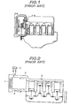
- Fig. 2 shows an arrangement disclosed in Japanese Patent Application Second Provisional Publication Sho. 57-57608. This arrangement has attempted to vaporize a liquid coolant and use the gaseous form thereof as a vehicle for removing heat from the engine.
- the radiator 1 and the coolant jacket 2 are in constant and free communication via conduits 3, 4 whereby the coolant which condenses in the radiator 1 is returned to the coolant jacket 2 little by little under the influence of gravity.
- this filter permits gaseous coolant to readily escape from the system, inducing the need for frequent topping up of the coolant level.
- a further problem with this arrangement has come in that some of the air, which is sucked into the cooling system as the engine cools, tends to dissolve in the water, whereby upon start up of the engine, the dissolved air tends to come out of solution and forms small bubbles in the radiator which adhere to the walls thereof and form an insulating layer. The undissolved air also tends to collect in the upper section of the radiator and inhibit the convection-like circulation of the vapor from the cylinder block to the radiator. This of course further deteriorates the performance of the device.
- European Patent Application Provisional Publication No. 0 059 423 published on September 8, 1982 discloses another arrangement wherein, liquid coolant in the coolant jacket of the engine, is not forcefully circulated therein and permitted to absorb heat to the point of boiling.
- the gaseous coolant thus generated is adiabatically compressed in a compressor so as to raise the temperature and pressure thereof and thereafter introduced into a heat exchanger (radiator). After condensing, the coolant is temporarily stored in a reservoir and recycled back into the coolant jacket via a flow control valve.
- This arrangement has suffered from the drawback that when the engine is stopped and cools down the coolant vapor condenses and induces sub-atmospheric conditions which tend to induce air to leak into the system. This air tends to be forced by the compressor along with the gaseous coolant into the radiator.
- Fig. 3 shows an evaporative type cooling system described in United States Patent No. 4,367,699 issued on Jan. 11, 1983 in the name of Evans.
- This arrangement features a separation tank 6 wherein gaseous and liquid coolant are initially separated.
- the liquid coolant is fed back to the cylinder block 7 under the influence of gravity while the relatively dry gaseous coolant (steam for example) is condensed in a fan cooled radiator 8.
- the temperature in the radiator is controlled to a predetermined constant level by selective energizations of the fan 9 which maintains a rate of condensation therein sufficient to provide a liquid seal at the bottom of the device. Condensate discharged from the radiator via the above mentioned liquid seal is collected in a small reservoir-like arrangement 10 and pumped back up to the separation tank via a small constantly energizedpump 11.
- Japanese Patent Application First Provisional Publication No. sho. 56-32026 discloses an arrangement wherein the structure defining the cylinder head and cylinder liners are covered in a porous layer of ceramic material 12 and wherein coolant is sprayed into the cylinder block from shower-like arrangements 13 located above the cylinder heads 14.
- the interior of the coolant jacket defined within the engine proper is essentially filled with gaseous coolant during engine operation at which time liquid coolant sprayed onto the ceramic layers 12.
- this arrangement has proven totally unsatisfactory in that upon boiling of the liquid coolant absorbed into the ceramic layers, the vapor thus produced and which escapes toward and into the coolant jacket, inhibits the penetration of fresh liquid coolant into the layers and induces the situation wherein rapid overheat and thermal damage of the ceramic layers 12 and/or engine soon results. Further, this arrangement is of the closed circuit type and is plagued with air contamination and blockages in the radiator similar to the compressor equipped arrangement discussed above.
- Fig. 5 shows an arrangement disclosed in United States Patent No. 1,737,562 published on Jan. 6, 1931 in the name of L P. Barlow.
- the coolant vapor which is condensed in the radiator 16 is first collected in the lower tank 17 of the radiator 16 and then transferred to the a larger reservoir 18 located below the same and returned to the coolant jacket 20 via a pump 22 which is controlled by a float type level sensor arrangement 23 located in the upper section of the coolant jacket 20.
- the pump 22 communicates with the coolant jacket 20 via a conduit 24 which is formed with a U -bend 25. This bend limits the amount of coolant which can drain back through the conduit 24 toward the reservoir 18.
- the interior of the radiator 16 and the reservoir 18 are both vented to the atmosphere via a conduit 26 and vent port 27 arrangement which fluidly interconnects the top of the reservoir 18 with lower tank 17 of the radiator.
- this arrangement also suffers from the problem that, during non-use, the interior of the radiator 16 and the upper section of the engine coolant jacket 20 are constantly exposed to atmospheric oxygen and accordingly prone to undergo rapid rusting and the like deterioration.
- cooling fan 28 is constantly driven by the engine and not controlled in response to the amount of heat produced by the engine and thus apt to consume unecessary energy.
- Fig. 6 shows an arrangement which is disclosed in United States Patent No. 4,549,505 issued on October 29, 1985 in the name of Hirano. The disclosure of this application is hereby incorporated by reference thereto. For convenience the same numerals as used in the above mentioned Patent are also used in Fig. 6.
- a lateral acceleration eg. high speed'cornering
- the system is disposed is subject to a lateral acceleration (eg. high speed'cornering) which can cause the low level of coolant in the lower tank at the bottom of the radiator to slant sufficiently that coolant vapor is permitted to be fed directly to the induction port of the coolant return pump.
- the above object is achieved via the use of a basic arrangement wherein a reservoir in which coolant is stored, is fluidly interposed between the downstream end of the condensor in which coolant vapor from the engine coolant jacket is condensed, and a coolant return pump which is responsive to a level sensor disposed in the coolant jacket, in a manner to form part of the cooling circuit of the system.
- the system further includes two temperature sensors, the first is disposed in the lower tank of the radiator and the other in the coolant jacket proximate the cylinder head.
- a device which modifies the pressure prevailing in the system is operated in response to one or both of the temperature sensors.
- the operation of a fan associated with the radiator is controlled in response to either the temperature sensor which is disposed in the lower tank alone or in response to both.
- the temperature difference between the coolant jacket and the lower tank is used to approximate how full the radiator is of liquid coolant and thus whether the operation of the fan is warrented or not.
- a single electromagnetic valve which is responsive to the second temperature sensor alone is use to control a coolant jacket/atmosphere vent in a manner to permit some of the coolant which fills the coolant jacket when the engine is not in use, to be drained rapidly therefrom at engine start-up to reduce warm-up time.
- a similar valve can be used to control a reservoir/atmosphere vent and enable the pressure in the system to be selectively raised in order to improve the heat exchange efficiency of the radiator.
- the valve is arranged to responsive to both of the temperature sensors.
- a first aspect of the present invention takes the form of an internal combustion engine having a structure subject to high heat flux and which is characterized by a cooling system comprising: a coolant jacket disposed about the structure and into which coolant is introduced in liquid form, permitted to boil and discharged in gaseous form; a radiator in fluid commuication with the coolant jacket which receives coolant vapor produced therein and condenses it to its liquid form, the radiator including a small collection vessel disposed at the bottom thereof; a reservoir in which coolant is stored, the reservoir being fluidly interposed between the collection vessel of the radiator and the coolant jacket; a level sensor disposed in the coolant jacket, the level sensor being arranged to sense the level of liquid coolant in the coolant jacket falling below a predetermined level and issues a signal indicative thereof, the predetermined level being selected to be such that the structure subject to high heat flux is immersed in a predetermined depth of liquid coolant; a pump which pumps liquid coolant from the reservoir to the coolant jacket through a coolant return
- a second aspect of the present invention comes in the form of a method of cooling an internal engine which is characterized by the steps of: introducing liquid coolant into a coolant jacket, permitting the coolant to boil and discharging the coolant in vaporized form; condensing the coolant vapor discharged from the coolant jacket in a radiator to form a condensate; storing liquid coolant in a reservoir; returning the condensate formed in the radiator to the reservoir; sensing the level of coolant in the coolant jacket using.
- a level sensor pumping liquid coolant from the reservoir to the coolant jacket in response to the level sensing step indicating that the level of liquid coolant in the coolant jacket is below a predetermined level; sensing the temperature of the condensate formed in the radiator; sensing the temperature of the coolant in the coolant jacket; and controlling a device associated with one of the radiator, the coolant jacket and the reservoir in a manner which controls the pressure prevailing within the cooling system.
- FIG. 7 of the drawings shows an engine system to which a first embodiment of the invention is applied.
- an internal combustion engine 200 includes a cylinder block 204 on which a cylinder head 206 is detachably secured.
- the cylinder head and block are formed with suitably cavities which define a coolant jacket 208 about structure of the engine subject to high heat flux (e.g. combustion chambers exhaust valves conduits, cylinder walls etc.,).
- a condensor 216 or radiator Fluidly communicating with a vapor discharge port 210 formed in the cylinder head 206 via a vapor manifold 212 and vapor conduit 214, is a condensor 216 or radiator as it will be referred to hereinafter.
- a selectively energizable electrically driven fan 218 Located adjacent the radiator 216 is a selectively energizable electrically driven fan 218 which is arranged to induce a cooling draft of air to pass over the heat exchanging surfaces of the radiator 216 upon being put into operation.
- the radiator 216 is preferably disposed at a well ventilated location such as near the front of the vehicle.
- Radiator 216 in this embodiment takes the form of upper and lower tanks 219, 220 which span the width of the device and a plurality relatively small diameter vertically extending tubes 221 interconnecting the same.
- the lower tank 220 is formed in a manner to have a larger internal volume than the upper one and thus function as a small collection reservoir or vessel.
- a coolant reservoir 224 is arranged to constantly communicate with the the lower tank 220 via a supply/discharge conduit 228.
- the reservoir 224 is closed by a cap in which an air bleed or vent 233 is formed. This permits the interior of the reservoir 224 to be maintained constantly at atmospheric pressure.
- reservoir 224 is arranged with respect to the coolant jacket so that under given modes of engine operation it is possible, by rendering the cooling jacket open to the ambient atmosphere and utilizing gravity, to bring about the situation wherein the level of coolant in the coolant jacket 208 and that in the reservoir 224 become equal at approximately a predetermined level "H". The reason for this particular arrangement will become clear hereinlater.
- a small capacity electrically driven pump 226 is disposed in a coolant return conduit 227 which leads from the reservoir 224 to an inlet port 229 formed at the bottom of the section of the coolant jacket formed in the cylinder block 204.
- the capacity of this pump 226 is selected to be such that it pumps coolant at a rate slightly greater than the maximum possible requirement of the cooling system. This rate can be approximated using parameters such as the amount of fuel combusted in the engine per unit time and confirmed by empirical results. It is important that the rate at which the pump 226 pumps be higher
- a level sensor 230 is disposed in the coolant jacket 208 and arranged to sense the level of coolant falling below the predetermined level H.
- H is selected to ensure that the engine structure which is subject to high heat flux (viz., the cylinder head, exhaust ports and valves) remains constanty immersed in a depth of liquid coolant sufficient to ensure constant immersion even under heavy load operation when the boiling of the coolant becomes so vigourous as to tend to induce localized dry-outs and cavitation. These phenomena are apt to cause localized overheating which can lead to serious engine damage.
- Level H is also selected in a manner to define a coolant vapor collection space in the coolant jacket 208 above the surface of the liquid to permit the vapor generated to accumulate and flow without undue restriction toward the vapor discharge port or ports 212 into the vapor manifold 212 and obviate the tendancy for large volumes of liquid coolant to be "blow out" of the coolant jacket 208.
- the level sensor 230 may take the form of a float and reed switch combination. It is deemed advantageous to arrange the level sensor 230 to output a signal when the coolant level is above H. With this, if the sensor 230 fails the pump will be continously energized ensuring that excess coolant rather than the reverse is supplied into the coolant jacket 208.
- the vapor manifold 212 in this embodiment is formed with a vent conduit 232.
- a ' normally closed electromagnetic valve 234 is disposed in this conduit 232 and arranged to open and permit fluid communication between the interior of the coolant jacket 208 and the ambient atmosphere, when energized. It is also possible to construct this valve so that the bias of the spring which holds the valve element in its closed position can be overcome by abnormally high pressures within the coolant jacket and associated elements and thus also function as a saftey relief valve.
- the vapor manifold is also provided with a liquid/vapor separator arrangement 236 which is located downstream of the vapor discharge port 212.
- a return conduit 238 leads from the bottom of the separator to a port 239 formed in the cylinder block proximate port 229.
- the separator 236 is shown to comprise a simple sump-like collection recess in the bottom wall of the vapor manifold 212.
- this device may include baffles or the like to improve the separation efficienty and/or take the form of arrangements disclosed in United States Patent No. 4,499,866 issued on Feb. 19, 1985 in the name of Hirano; United States Patent No. 4,570,579 issued on Feb. 18, 1986 in the name of Hirano; copending United States Patent Application Serial No.
- the provision of the liquid/vapor separator 236 minimizes the amount of liquid coolant which is permitted to flow through the vapor transfer conduit 214 and find its way into the radiator 216.
- a relatively large amount of fuel is fed to and combusted in the combustion chambers of the engine. This produces a large amount of heat which induces extremely vigorous boiling in and around the cylinder head of the engine. The bumping and frothing which accompanies this vigourous boiling tends to induce the discharge of a relatively large amount of liquid coolant into the vapor manifold 212.
- the liquid coolant if permitted to enter the upper tank 219 of the radiator 216, tends to wet and thus insulate the interior of the conduits 221 to the point whereat the "dry" surface area available for the coolant vapor to release its latent heat of evaporation is drastically reduced and the heat exchange capacity of the radiator is adversely effected inducing the possibility of engine overheat due to the inability to release sufficiently large amounts of heat.
- a (first) temperature sensor 240 is disposed in the lower tank 220 and arranged to sense the temperature of the coolant which has collected therein.
- the output of this sensor alone is used to control the operation of fan 218.
- the sensor is arranged to induce energization of the fan upon the temperature of the coolant in the lower tank 220 exceeding a value which is selected to fall in the range of 90 to 100°C. Viz., under actual operation the temperature or the condensate in the lower tank approximates the temperature at which the coolant vapor enters the upper tank 219.
- a (second) temperature sensor 244 is disposed in the coolant jacket 208 proximate the most highly heated engine structure and arranged to be immersed in the liquid coolant. With this arrangement the immersion of the sensor 244 in liquid coolant stablizes the output thereof ensuring error free operation even when the coolant is boiling and bumping vigourously. In the event of an excessive lack of coolant in the coolant jacket 208 which permits the sensor to be directly exposed to heat radiation from the structure of the cylinder head 206 or the like, the resulting abnormally high temperature signal can be used to indicate a malfunction.
- the output of temperature sensor 244 is used to control the energization of valve 234.
- the temperature sensor 244 is arranged to issue a signal which energizes and opens the valve 234 when the temperature of the coolant jacket is at or below 45°C (by way of example). Viz., a temperature which is indicative of the engine 200 being "cold" and not having been used in the just immediate past and at which the coolant jacket 208, radiator 211 will inevitably be filled with liquid coolant.
- a vehicle cabin heating arrangement comprises a heater core 246 a induction conduit 248, a discharge
- the induction conduit 248 is arranged to communicate with a section of the coolant jacket 208 formed in the cylinder block 208 while the dischage conduit 250 communicates with a section of the coolant jacket 208 which is formed in the cylinder head 206.
- the discharge conduit 250 is arranged to discharge coolant which has passed through the heater core 246 into the coolant jacket 208 at level which lower than the above mentioned level H.
- the operation of the circulation pump 252 is controlled in accordance with a manually operable switch (not shown).
- the operation of the first emboidment is such that when the engine 200 is stopped and cools the coolant vapor which fills the upper sections of the coolant jacket 208, radiator 216, vapor manifold and vapor transfer conduit 212, 214 condenses and induces a negative pressure which inducts coolant from the reservoir 224 via conduit 228 until the coolant jacket 208 vapor manifold 212, radiator 216 and associated conduiting are completely filled with coolant or the pressure differential between the coolant jacket 208 (for example) and the ambient atmosphere becomes zero.
- the fan 218 is subject to the control of the temperature sensor 240.
- the cooling fan 218 Upon the temperature of the coolant in the lower tank 220 reaching the given level the cooling fan 218 is energized. If the rate of condensation induced by the fan 218 and or by the influence of environmental ambient effects such as natural drafts, low temperatures etc., is such as to exceed the rate at which coolant vapor is being produced, the pressure in the system drops below atmospheric and inducts coolant from the reservoir 2.24 into the lower tank 220 via conduit 228 in a manner which decreases the temperature prevailing in the lower tank and which increases the level of liquid in the conduits 221. This reduces the amount ot "dry" surface area available for the latent heat of the coolant vapor to be released, stops the operation of the fan 218 and induces the situation wherein the rate of condensation is automatically matched with the rate of vapor generation.
- the temperature sensor 244 If at this time the temperature sensor 244 outputs a signal indicative of the engine being "cold” (viz., outputs a high level voltage signal) then a "quick warm-up" mode is entered.
- the electromagnetic valve 234 is opened and atmospheric air temporarily allowed into the system via vent conduit 232. This allows the coolant which is filling the coolant jacket 208 etc., to drain rapidly into the reservoir 224 until the levels become equal such as shown in Fig. 7 for example).
- the reservoir 224 By arranging the reservoir 224 at an appropriate level as mentioned hereinbefore, and ensuring that an appropriate amount of coolant is contained in the latter, then is an easy matter to simply allow the levels to simply equalize at level H.
- the reservoir 224 is not located as illustrated (viz., is located at a lower level) and or there is the possiblity that the reservoir 224 may not always be appropriately filled with liquid coolant, then it is within the scope of the invention as a variant the first embodiment to
- the coolant return pump 226 replenishes the evaporated coolant in a manner that maintains the liquid level in the coolant jacket at level H.
- the heat efficiency of the radiator 216 is usually impaired thus causing a pressure build-up which hastens the purging of the non-condensible matter.
- the thermally insulating air forms pockets in the radiator conduiting 221 which prevents the coolant vapor from releasing its latent heat and thus tends to be pushed toward the bottom of the radiator by the lighter and hotter coolant vapor which is constantly being generated in the coolant jacket 208.
- Figs. 8 and 10 pertain to a second embodiment of the present invention.
- the output of the second temperature sensor 244 is used in combination with the first one 240 in a manner to derive a temperature differential which is indicative of the amount of liquid coolant contained in the heat exchanging section of the radiator and thus enable a decision as to whether it is useful to operate the fan 218 or not.
- the amount of condensation which occurs in the radiator 216 is subject to not only the operation of the fan 218 but to external influences as well.
- the temperature at which the fan operated in a range of 80 - 85°C when ethylene glycol anti-freeze/water is used as the engine coolant - it being noted that this solution boils at about 105°C at sea level) to allow for the situations wherein the vehicle is operated at high altitudes (e.g. mountainous areas) and the atmospheric pressure is lower than at sea level.
- the relatively large temperature differential which naturally develops between the coolant jacket 208 and the lower tank 220 at this time can be used to indicate that fan operation is not required and thus be used to inhibit wasteful energization.
- the level of liquid coolant in the radiator conduiting 221 tends to rise in repsonse to the high rate of condensation which is induced by the ambient conditions and "automatically” reduce the "dry" area available for latent heat release to the appropriate degree.
- the natural draft of air passing over the conduits 221 of the radiator 216 can be all but non-existent.
- the temperature in the lower tank 220 gradually approaches the temperature at which the coolant vapor is introduce into the upper tank 219.
- the radiator 216 tends to fill with uncondensed hot coolant vapor. This causes the temperature of the liquid coolant in the lower tank 220 to rise toward that prevailing in the coolant jacket 208 and reduces the value of the temperature differential therebetween.
- Energization of the fan 218 under such conditions increases the rate of condensation within the radiator 216. By maintaining the energization until the temperature differential increase to a given valve the rate of condensation can be matched with the rate of vapor generation, prevent the situation wherein coolant vapor escapes to the reservoir 224 and maintains the required control of the system.
- Fig. 10 shows in flow chart form the steps which are executed in a microprocessor (not shown) included in a control circuit 300 to which the outputs of level sensor 230 and temperature sensors 240, 244 are fed.
- step 1002 if the temperature of the liquid in the coolant jacket is found at step 1002 to be less than a predetermined level (80°C for example) the operation of the fan is inhibited (step 1003). Under these conditions the coolant will normally not be boiling even if the vehicle has ascended a high mountain. At step 1004 the temperature differential which exists between the coolant jacket and the lower tank is ranged.
- a predetermined level 80°C for example
- TE engine temp
- TC condensor temp
- step 1005 the program flows directly to step 1005, while in the event that the differential is less than 8°C at step 1006 a command to energize fan 218 is issued. In the event that the temperature differential is greater than 10°C then the operation of the fan 218 is stopped (step 1007).
- step 1005 to 1009 the output of level sensor 230 is sampled and the appropriate pump control implemented to ensure that the level of coolant does not fall below level H.
- the status of the engine is determined. Viz., it is determined if the engine is running or not. This can be determined by sampling the output of a engine speed sensor or the engine distibutor and determing if the engine speed is above or below a given low value - for example 100 RPM. If the engine is found to be running then the program flows to step 1011 wherein a timer (a soft clock by way of example) is cleared whereafter it recycles to step 1002.
- a timer a soft clock by way of example
- the timer can be set up to count up by 1 each run of the program and to be reset to zero or some predetermined value wheneve step 1011 is implemented.
- step 1010 the engine is found to have stopped then at step 1012 the current count of the timer is sampled and if the count has exceeded a value indicative of 30 seconds (for exmple) the program ends terminating the control of the system and cutting off the supply of power to the fan 218 and other circuitry.
- the program recycles. This ensures that the system will reamain operative for a short period of time after the engine is stopped so as to allow for the heat which has accumulated in the engine structure etc., to be released sufficiently to the atmosphere and allow for the thermal inertia which will keep the coolant boiling and possibly generate undesirably high pressures within the system.
- a one-way check valve 302 is disposed in the coolant return conduit 227 at a location intermediate of the coolant return pump 226 and port 229. This provision prevents coolant from draining back through the coolant return conduit toward the reservoir 224 in the event that the pump 226 is not of a construction which inherently inhibits such a reverse flow.
- Figs. 9, 11 and 12 pertain to a third embodiment of the present invention.
- the cooling system to which the third embodiment is applied features a construction essentially the same as that of the second embodiment save the provision of a normally open electromagnetic valve 330 which is arranged to selectively energizable to close the reservoir vent 234.
- the provision of this valve enables the pressure and temperature in the radiator 216 and coolant jacket 208 to be selectively raised in a manner which prevents the loss of coolant vapor and increases the temperature differential which exists between the interior of radiator and that of the cooling medium (in this case atmospheric air) in contact with the exterior thereof.
- shut-down mode wherein the heat accumulated in the engine is released via the cooling system for a short period following engine stoppage.
- Figs. 11 and 12 show in flow chart form the steps which are performed by a microprocessor included in the control circuit 300 in accordance with the third embodiment.
- the output of temperature sensor 244 is sampled in step 2001 and the determination made as to whether the temperature prevailing in the coolant jacket 208 is above or below a given level which in this case is selected to be 80°C. If the coolant is found to be "cold” then the program flows to step 202 wherein a command to stop the operation of fan 218 is issued. As will be appreciated if the coolant is "cold” there is clearly no need to operate the fan irrespective of the temperature differential between the coolant jacket and the radiator as both are apt to be completely or nearly filled with liquid.
- the outputs of temperature sensors 244 and 240 are compared and the differential ranged. If the ranging reveals that the temperature differential is (a) between 8 and 10 degrees things are left as they are and the program flows to step 2010; (b) greater than 10°C then at step 2009 the fan operation is inhibited; (c) beteeen 4 and 8°C then at step 2008 a command to energize fan 218 is issued; and (d) if less than 4 0 C then as step 2004 the status of FLAG is determined. If the flag is found to be "1” then the program flows to step 2008. However, if the value of the flag is found to be "0” then the program flows to step 2005.
- steps 2005 and 2006 the value of the flag is set to "1" and a command to close valve 330 via energization is issued.
- flag "0" is used to indicate that valve 330 is open while the valve "1" denotes a closed or energized condition.
- step 2007 the value of TEO the coolant jacket temperature at which valve 330 was closed is recorded in RAM and at step 2008 a command to energize fan 218 is issued.
- the instant status of FLAG is determined. If the value is "1" indicating that valve 330 is closed, then at step 2011 the recorded value of TEO minus 3°C is compared with the instant output of temperature sensor 244 and the latter compared with a maximum permissible value of 120°C.
- steps 2015 to 2017 are executed in order to ensure that the level of liquid coolant in the coolant jacket 208 is prevented from falling below level B and the program recycles to step 2001.
- Fig. 12 shows in flow chart form the steps which are performed as an interrupt program in order to determine the instant status of the engine. Viz., determine whether the engine is running or not and whether it is necessary to execute the steps of a "shut-down" program. This interrupt is performed at predetermined frequent intervals.
- the first step of this program is such as to sample the output of device such as the ignition inition key, an engine speed sensor or ignition system and determine if the engine is still running or has stopped. In the event that the engine is still operating then the program flows to step 3002 wherein the current count of a soft clock or timer is cleared and the program returns to that shown in Fig. 11.
- the program proceeds into the shut-down control section thereof.
- the coolant jacket temperature is determined and ranged against a predetermined value of 85°C. In the event that this enquiry reveals that the engine coolant is cold (below 85°C)
- step 3004 the power to the system is cut-off.
- valve 330 is energized so as to assume a closed state and close off the radiator 216 from the ambient atmosphere. This now conditions the system so that the temperature and pressure in the radiator can be selectively elevated to increase the heat exchange ability of the same and thus speed up the final cooling of the engine.
- step 3006 the temperature differential between the coolant jacket coolant and the condensate in the lower tank 220 of the radiator 216 is determined. If the differential is greater than 20°C then the program flows to step, if less than 10°C at step 3007 fan 218 is energized while if within a range of 10 to 20°C at steps 3008 and 3009 commands to energize the coolant return pump 226 and de-energize fan 218 are issued.
- the radiator 216 is at least partially filled with the liquid coolant and that the chances of vapor loss to the atmosphere are negligible. However, if the differential is low then is may be assumed that the radiator 216 still contains a relatively large amount of coolant vapor and that the energization of the fan will have the desired effect on the rate of condensation. On the other hand if the temperature is within a predetermined range of 10 - 20°C then it can be assumed that the most practical course of cooling the engine is tc pump cool coolant from the reservoir 224 into th coolant jacket 208. As valve 330 is closed at this this pulping operation
- Steps 3007 steps 3010 to 3012 are such as to ensure that the post engine operation boiling does not accidently lower the liquid coolant level to the point that thermal damage to the same can occur.
- step 3013 it is again determined if the engine is running or not. If the engine is found to be running then at step 3014 valve 330 is opened and the program returns via step 3002. On the other hand, if this enquiry confirms that the engine is not running then at step 3015 the count of the timer is sampled to determine if the engine has been stopped for at least 30 seconds. Until the count amounts to this value then the program recycles to step 3003.
- Figs. 8, 13 and 14 pertain to a fourth embodiment of the present invention.
- This embodiment is essentially the same as the third one save that it does not require the provision of the electromagnetic valve 330.
- the fan 218 is used to control the temperature of the coolant in the coolant jacket 208 while in the event that the engine is stopped both the fan 218 and the coolant return pump 226 are selectively operated.
- the operation of the fourth embodiment is similar to that of the third one.
- Fig. 13 shows the steps which characterize the control executed by a system control routine according to to the fourth embodiment.
- Fig. 14 shows the interrupt routine which is run a predetermined time intervals in order to determine the need to implement "shut-down" control.
- Figs. 9 and 15 pertain to a fifth embodiment of the present invention.
- This embodiment is basically similar to the third one save that the system control routine includes the steps executed in the interrupt routine of the third embodiment.
- the operation and effect this embodiment will be clear from the disclosure relating to the third embodiment given hereinbefore. Further redundant disclosure will be omitted for brevity.
Landscapes
- Engineering & Computer Science (AREA)
- Chemical & Material Sciences (AREA)
- Combustion & Propulsion (AREA)
- Mechanical Engineering (AREA)
- General Engineering & Computer Science (AREA)
- Combined Controls Of Internal Combustion Engines (AREA)
- Cooling, Air Intake And Gas Exhaust, And Fuel Tank Arrangements In Propulsion Units (AREA)
Applications Claiming Priority (10)
| Application Number | Priority Date | Filing Date | Title |
|---|---|---|---|
| JP15756385U JPH032670Y2 (de) | 1985-10-15 | 1985-10-15 | |
| JP157563/85U | 1985-10-15 | ||
| JP235428/85 | 1985-10-23 | ||
| JP23542885A JPS6296722A (ja) | 1985-10-23 | 1985-10-23 | 内燃機関の沸騰冷却装置 |
| JP6679086A JPH0713459B2 (ja) | 1986-03-25 | 1986-03-25 | 内燃機関の沸騰冷却装置 |
| JP66790/86 | 1986-03-25 | ||
| JP7784386A JPS62237021A (ja) | 1986-04-04 | 1986-04-04 | 内燃機関の沸騰冷却装置 |
| JP77844/86 | 1986-04-04 | ||
| JP77843/86 | 1986-04-04 | ||
| JP61077844A JPH076384B2 (ja) | 1986-04-04 | 1986-04-04 | 内燃機関の沸騰冷却装置 |
Publications (3)
| Publication Number | Publication Date |
|---|---|
| EP0219099A2 true EP0219099A2 (de) | 1987-04-22 |
| EP0219099A3 EP0219099A3 (en) | 1988-07-20 |
| EP0219099B1 EP0219099B1 (de) | 1991-09-11 |
Family
ID=27524006
Family Applications (1)
| Application Number | Title | Priority Date | Filing Date |
|---|---|---|---|
| EP86114221A Expired EP0219099B1 (de) | 1985-10-15 | 1986-10-14 | Kühlsystem für eine Brennkraftmaschine |
Country Status (3)
| Country | Link |
|---|---|
| US (1) | US4721071A (de) |
| EP (1) | EP0219099B1 (de) |
| DE (1) | DE3681395D1 (de) |
Families Citing this family (9)
| Publication number | Priority date | Publication date | Assignee | Title |
|---|---|---|---|---|
| DE3809136C2 (de) * | 1987-04-02 | 2001-07-26 | Volkswagen Ag | Einrichtung zur Verdampfungskühlung einer Brennkraftmaschine und zum Betreiben eines Heizungswärmetauschers durch das Kühlmittel |
| US5435485A (en) * | 1992-07-24 | 1995-07-25 | Gas Research Institute | Automatic purge system for gas engine heat pump |
| JP3230923B2 (ja) * | 1994-03-29 | 2001-11-19 | 株式会社東芝 | 原子炉水位測定装置 |
| US5582138A (en) * | 1995-03-17 | 1996-12-10 | Standard-Thomson Corporation | Electronically controlled engine cooling apparatus |
| US6959670B2 (en) * | 2002-06-17 | 2005-11-01 | Kuo Chang Lin | Engine system having opened water tank cover |
| KR101339257B1 (ko) * | 2012-09-24 | 2013-12-09 | 현대자동차 주식회사 | 차량의 엔진 냉각 시스템 및 방법 |
| US9719409B2 (en) | 2014-12-26 | 2017-08-01 | Ford Global Technologies, Llc | Method and system for engine cooling system control |
| KR101724462B1 (ko) * | 2015-09-18 | 2017-04-07 | 현대자동차 주식회사 | 마일드 하이브리드 차량의 엔진 냉각 시스템 및 방법 |
| CN115790009A (zh) * | 2022-09-28 | 2023-03-14 | 重庆长安汽车股份有限公司 | 一种电动车辆冷却系统监控装置与方法 |
Family Cites Families (16)
| Publication number | Priority date | Publication date | Assignee | Title |
|---|---|---|---|---|
| US1338722A (en) * | 1916-06-02 | 1920-05-04 | Essex Motors | Cooling apparatus for internal-combustion engines |
| US1632582A (en) * | 1926-12-30 | 1927-06-14 | Lester P Barlow | Engine-cooling system |
| US1787562A (en) * | 1929-01-10 | 1931-01-06 | Lester P Barlow | Engine-cooling system |
| US2083611A (en) * | 1931-12-05 | 1937-06-15 | Carrier Corp | Cooling system |
| DE714662C (de) * | 1939-07-27 | 1941-12-04 | Ernst Heinkel Flugzeugwerke G | Verdampfungskuehleinrichtung fuer Brennkraftmaschinen in Flugzeugen |
| US2292946A (en) * | 1941-01-18 | 1942-08-11 | Karig Horace Edmund | Vapor cooling system |
| US3981279A (en) * | 1975-08-26 | 1976-09-21 | General Motors Corporation | Internal combustion engine system |
| HU176054B (en) * | 1978-11-30 | 1980-12-28 | Autoipari Kutato Intezet | Automatic deaeration plant for forced-flowing fluid system particularly for cooling system of internal combustion engine |
| US4367699A (en) * | 1981-01-27 | 1983-01-11 | Evc Associates Limited Partnership | Boiling liquid engine cooling system |
| JPS6093117A (ja) * | 1983-10-26 | 1985-05-24 | Nissan Motor Co Ltd | 沸騰冷却式インタ−ク−ラ装置 |
| JPS60108526A (ja) * | 1983-11-17 | 1985-06-14 | Nissan Motor Co Ltd | エンジンの沸騰冷却装置 |
| JPS60164614A (ja) * | 1984-02-07 | 1985-08-27 | Nissan Motor Co Ltd | 過給機付エンジンの沸騰冷却装置 |
| JPS60175728A (ja) * | 1984-02-23 | 1985-09-09 | Nissan Motor Co Ltd | エンジンの沸騰冷却装置 |
| JPS6125910A (ja) * | 1984-07-16 | 1986-02-05 | Nissan Motor Co Ltd | エンジンの沸騰冷却装置 |
| DE3513126C2 (de) * | 1985-04-12 | 1987-02-12 | Daimler-Benz Ag, 7000 Stuttgart | Flüssigkeitsgekühlter Vierventil-Zylinderkopf für eine mehrzylindrige Brennkraftmaschine |
| JPS6258010A (ja) * | 1985-09-06 | 1987-03-13 | Nissan Motor Co Ltd | 内燃機関の沸騰冷却装置 |
-
1986
- 1986-10-14 EP EP86114221A patent/EP0219099B1/de not_active Expired
- 1986-10-14 DE DE8686114221T patent/DE3681395D1/de not_active Expired - Fee Related
- 1986-10-14 US US06/918,052 patent/US4721071A/en not_active Expired - Lifetime
Also Published As
| Publication number | Publication date |
|---|---|
| DE3681395D1 (de) | 1991-10-17 |
| US4721071A (en) | 1988-01-26 |
| EP0219099B1 (de) | 1991-09-11 |
| EP0219099A3 (en) | 1988-07-20 |
Similar Documents
| Publication | Publication Date | Title |
|---|---|---|
| EP0143326B1 (de) | Kühlvorrichtung für eine Kraftfahrzeugmaschine | |
| US4788943A (en) | Cooling system for automotive engine or the like | |
| EP0207354B1 (de) | Verfahren und Vorrichtung zum Kühlen von Fahrzeugbrennkraftmaschinen | |
| EP0214389B1 (de) | Kühleinrichtung für Kraftfahrzeugmaschine | |
| US4766852A (en) | Cooling system for automotive engine or the like | |
| US4648357A (en) | Cooling system for automotive engine or the like | |
| US4658766A (en) | Cooling system for automotive engine or the like | |
| US4721071A (en) | Cooling system for automotive engine or the like | |
| US4782795A (en) | Anti-knock system for automotive internal combustion engine | |
| EP0161687B1 (de) | Kühlungsanlage für eine Kraftwagenmaschine | |
| US4622925A (en) | Cooling system for automotive engine or the like | |
| US4694784A (en) | Cooling system for automotive engine or the like | |
| US4628872A (en) | Cooling system for automotive engine or the like including coolant return pump back-up arrangement | |
| US4570579A (en) | Vapor cooled internal combustion engine coolant jacket | |
| EP0146057B1 (de) | Kühlungsvorrichtung für Kraftwagenmaschinen | |
| US4630573A (en) | Cooling system for automotive engine or the like | |
| US4722304A (en) | Cooling system for automotive engine or the like | |
| US4605164A (en) | Cabin heating arrangement for vehicle having evaporative cooled engine | |
| EP0167169B1 (de) | Kühlvorrichtung für eine Kraftfahrzeugmaschine | |
| US4662318A (en) | Cooling system for automotive internal combustion engine or the like | |
| EP0153694B1 (de) | Kühlverfahren und Kühlsystem für Brennkraftmaschinen | |
| US4627397A (en) | Cooling system for automotive engine or the like | |
| US4624221A (en) | Cooling system for automotive engine or the like | |
| US4686942A (en) | Cooling system for automotive engine or the like | |
| EP0189881B1 (de) | Kühlvorrichtung einer Kraftfahrzeugmaschine |
Legal Events
| Date | Code | Title | Description |
|---|---|---|---|
| PUAI | Public reference made under article 153(3) epc to a published international application that has entered the european phase |
Free format text: ORIGINAL CODE: 0009012 |
|
| 17P | Request for examination filed |
Effective date: 19861014 |
|
| AK | Designated contracting states |
Kind code of ref document: A2 Designated state(s): DE FR GB |
|
| PUAL | Search report despatched |
Free format text: ORIGINAL CODE: 0009013 |
|
| AK | Designated contracting states |
Kind code of ref document: A3 Designated state(s): DE FR GB |
|
| 17Q | First examination report despatched |
Effective date: 19890629 |
|
| GRAA | (expected) grant |
Free format text: ORIGINAL CODE: 0009210 |
|
| AK | Designated contracting states |
Kind code of ref document: B1 Designated state(s): DE FR GB |
|
| PGFP | Annual fee paid to national office [announced via postgrant information from national office to epo] |
Ref country code: FR Payment date: 19911007 Year of fee payment: 6 |
|
| REF | Corresponds to: |
Ref document number: 3681395 Country of ref document: DE Date of ref document: 19911017 |
|
| ET | Fr: translation filed | ||
| PLBE | No opposition filed within time limit |
Free format text: ORIGINAL CODE: 0009261 |
|
| STAA | Information on the status of an ep patent application or granted ep patent |
Free format text: STATUS: NO OPPOSITION FILED WITHIN TIME LIMIT |
|
| 26N | No opposition filed | ||
| PG25 | Lapsed in a contracting state [announced via postgrant information from national office to epo] |
Ref country code: FR Effective date: 19930630 |
|
| REG | Reference to a national code |
Ref country code: FR Ref legal event code: ST |
|
| PGFP | Annual fee paid to national office [announced via postgrant information from national office to epo] |
Ref country code: GB Payment date: 19981016 Year of fee payment: 13 |
|
| PGFP | Annual fee paid to national office [announced via postgrant information from national office to epo] |
Ref country code: DE Payment date: 19981023 Year of fee payment: 13 |
|
| PG25 | Lapsed in a contracting state [announced via postgrant information from national office to epo] |
Ref country code: GB Free format text: LAPSE BECAUSE OF NON-PAYMENT OF DUE FEES Effective date: 19991014 |
|
| GBPC | Gb: european patent ceased through non-payment of renewal fee |
Effective date: 19991014 |
|
| PG25 | Lapsed in a contracting state [announced via postgrant information from national office to epo] |
Ref country code: DE Free format text: LAPSE BECAUSE OF NON-PAYMENT OF DUE FEES Effective date: 20000801 |