EP0218889A2 - Transport and storage device for radioactive materials - Google Patents
Transport and storage device for radioactive materials Download PDFInfo
- Publication number
- EP0218889A2 EP0218889A2 EP86112234A EP86112234A EP0218889A2 EP 0218889 A2 EP0218889 A2 EP 0218889A2 EP 86112234 A EP86112234 A EP 86112234A EP 86112234 A EP86112234 A EP 86112234A EP 0218889 A2 EP0218889 A2 EP 0218889A2
- Authority
- EP
- European Patent Office
- Prior art keywords
- cover
- collar
- openings
- pin
- recesses
- Prior art date
- Legal status (The legal status is an assumption and is not a legal conclusion. Google has not performed a legal analysis and makes no representation as to the accuracy of the status listed.)
- Granted
Links
Images
Classifications
-
- G—PHYSICS
- G21—NUCLEAR PHYSICS; NUCLEAR ENGINEERING
- G21F—PROTECTION AGAINST X-RADIATION, GAMMA RADIATION, CORPUSCULAR RADIATION OR PARTICLE BOMBARDMENT; TREATING RADIOACTIVELY CONTAMINATED MATERIAL; DECONTAMINATION ARRANGEMENTS THEREFOR
- G21F5/00—Transportable or portable shielded containers
- G21F5/06—Details of, or accessories to, the containers
- G21F5/12—Closures for containers; Sealing arrangements
Definitions
- the invention relates to a transport and storage device for radioactive materials consisting of a cylindrical container.
- the container is made with a closed casing made of steel, concrete or cast iron and has an opening at the front that can be closed by a lid.
- An end face of the cover can be pressed against an end face of the casing.
- An edge surface of the cover is covered by a collar formed from the casing. Radial openings are provided in a uniform distribution over the circumference of the collar. These are opposite recesses arranged in the lid.
- Such a transport and storage device is known from DE-OS 33 31 892 and, despite the relatively inexpensive construction, nevertheless meets the high requirements to be placed on the safety of transport and storage devices for radioactive material.
- the invention has for its object to simplify a device of the type described in terms of its manufacture and handling, without thereby affecting its high level of functional reliability.
- the recesses which are conically narrowed towards the center of the cover and the pressable therein, which are guided in the openings of the collar, fulfill both the function of the screws and the cylindrical bolts of the known device, so that only one is required instead of two differently designed groups of connecting and fastening means is. Due to the conicity of the pins and the recesses according to the invention, the end face of the cover can be pressed axially firmly against an end face of the casing and at the same time also radially aligned and fixed.
- each pin has a continuous concentric bore for a threaded pin, which can be screwed into a threaded hole in the bottom of the recess.
- This configuration ensures permanent cover locking even when the pins should tend to move radially outwards out of the recesses due to their relatively strong conicity.
- each threaded bolt consists of an Allen screw which can be countersunk in the pin with its head.
- Each Allen screw can be fixed against unintentional loosening according to a further embodiment of the invention by means of a circlip that can be inserted in the bore of the pin.
- the pins can also be welded to the collar of the wall to secure the lid closure, which is particularly recommended if the container loaded with radioactive material is to serve as an intermediate or final storage device.
- the low manufacturing costs of the device according to the invention are particularly important.
- the device consists of a cylindrical container, the closed casing 1 of which is made of steel and concrete 4 clad with steel sheets 2 and 3 on the inside and outside.
- a cover washer 5 is welded to the steel sheets 2 and 3, which serve as lost formwork for the steel-concrete 4, which is flush with the upper end face of the steel sheet 2 forming the inside cladding and is thus towered over by the steel sheet 3 forming the outside cladding that the protruding part of the steel sheet 3 forms a collar 6.
- An end opening of the container can be closed by a lid 7, which is also made of steel-concrete 8 and is clad on both end faces with sheet steel disks 9 and 10 and on its edge face with a sheet steel cylinder 11.
- the cover 7 lies with an edge surface 12 of the sheet steel disc 9 facing the interior of the container on the cover ring disc 5, while the steel sheet cylinder 11 of the cover 7 is laterally covered over its full height by the collar 6 formed from the steel sheet 3.
- a base plate 13 is welded to the underside of the steel sheet disc 9, which has a diameter that is slightly larger than the inside diameter of the container and extends into a recess 14 in the edge region of the steel sheet 2.
- a cover plate 15 is welded onto the upper side of the sheet steel plate 10 and has a diameter which is slightly larger than the inside diameter of the collar 6 and can be welded to the end face thereof.
- openings 16 are provided in the sheet steel cylinder.
- a radially aligned insert 17 is welded to the sheet steel cylinder 11, which is additionally welded to the sheet steel disk 9 via a radial web 18 and is cast in the steel concrete 8 of the cover 7.
- Each insert 17 has a recess 19 which is conically narrowed towards the center of the cover 7, the cone angle of which in the exemplary embodiment is approximately 11 °, 25 '.
- a threaded bore 21 is provided in the bottom 20 of the insert 17 coaxially with the recess 19.
- openings 22 in the collar 6 which are aligned with the openings 16 in the sheet steel cylinder 11 are provided.
- a conical pin 23 the cone angle of which coincides with that of the recesses 19, can be driven in, a corresponding wall thickness of the collar 6 ensuring that the pin 23 receives a reliable guidance through the reveal of the openings 22.
- each pin 23 is provided with a continuous coaxial bore 24, in which a threaded bolt 25 in the form of an Allen screw can be inserted and screwed into the threaded bore 21 in the base 20 of the insert 17.
- a threaded bolt 25 in the form of an Allen screw can be inserted and screwed into the threaded bore 21 in the base 20 of the insert 17.
- a circlip can finally be inserted into the enlarged part of the bore 24 or the head 26 can be welded to the collar 6.
- the same effect can be achieved with a plate that completely or partially covers the opening of the bore 24 and is also welded to the collar 6 if the head 26 in the end position of the pin 23 is flush with the outside of the collar 6.
Abstract
Description
Die Erfindung bezieht sich auf eine aus einem zylindrischen Behälter bestehende Transport- und Lagervorrichtung für radioaktive Stoffe. Der Behälter ist mit einer geschlossenen Ummantelung aus Stahl, Beton oder Gußeisen hergestellt und weist stirnseitig eine durch einen Deckel verschließbare Öffnung auf. Eine Stirnfläche des Deckels ist gegen eine Stirnfläche der Ummantelung anpreßbar. Eine Randfläche des Deckels ist von einem aus der Ummantelung gebildeten Kragen abgedeckt. In gleichmäßiger Verteilung über den Umfang des Kragens sind radiale Durchbrüche vorgesehen. Diesen liegen im Deckel angeordnete Aussparungen gegenüber.The invention relates to a transport and storage device for radioactive materials consisting of a cylindrical container. The container is made with a closed casing made of steel, concrete or cast iron and has an opening at the front that can be closed by a lid. An end face of the cover can be pressed against an end face of the casing. An edge surface of the cover is covered by a collar formed from the casing. Radial openings are provided in a uniform distribution over the circumference of the collar. These are opposite recesses arranged in the lid.
Eine derartige Transport- und Lagervorrichtung ist aus der DE-OS 33 31 892 bekannt und erfüllt trotz des verhältnismäßig kostengünstigen Aufbaues dennoch die an die Sicherheit von Transport- und Lagervorrichtungen für radioaktives Material zu stellenden hohen Anforderungen.Such a transport and storage device is known from DE-OS 33 31 892 and, despite the relatively inexpensive construction, nevertheless meets the high requirements to be placed on the safety of transport and storage devices for radioactive material.
Bei der bekannten Vorrichtung dienen zur sicheren Befestigung des Deckels auf der Behälteröffnung sowohl Schrauben, die den Deckel axial durchdringen und in in die Ummantelung des Behälters eingebettete Gewindebuchsen eindrehbar sind, wie auch zylindrische Bolzen, welche den Kragen der Ummantelung des Behälters radial durchdringen und in entsprechende Aussparungen im Deckel eingreifen.In the known device serve for secure attachment of the lid on the container opening both screws that penetrate the lid axially and can be screwed into threaded jacks embedded in the casing of the container, as well as cylindrical bolts that penetrate the collar of the casing radially and into corresponding Engage recesses in the lid.
Der Erfindung liegt die Aufgabe zugrunde, eine Vorrichtung der eingangs beschriebenen Art hinsichtlich ihrer Herstellung und Handhabung zu vereinfachen, ohne dadurch ihre hohe Funktionssicherheit zu beeinträchtigen.The invention has for its object to simplify a device of the type described in terms of its manufacture and handling, without thereby affecting its high level of functional reliability.
Zur Lösung dieser Aufgabe wird von einer Vorrichtung der im Oberbegriff des Anspruchs 1 genannten gattungsgemäßen Art ausgegangen, die erfindungsgemäß die im kennzeichnenden Teil des Patentanspruchs 1 genannten Merkmale aufweist.To achieve this object, a device of the generic type mentioned in the preamble of claim 1 is assumed, which according to the invention has the features mentioned in the characterizing part of patent claim 1.
Die erfindungsgemäß zum Deckelzentrum hin konisch verengten Aussparungen und die darin einpreßbaren, in den Durchbrüchen des Kragens geführten konischen Zapfen erfüllen sowohl die Funktion der Schrauben wie auch der zylindrischen Bolzen der bekannten Vorrichtung, so daß dazu anstelle zweier unterschiedlich ausgebildeter Gruppen von Verbindungsund Befestigungsmitteln lediglich eine erforderlich ist. Durch die erfindungsgemäße Konizität der Zapfen und der Aussparungen läßt sich der Deckel axial mit seiner Stirnfläche fest gegen eine Stirnfläche der Ummantelung pressen und gleichzeitig auch radial ausrichten und fixieren.The recesses which are conically narrowed towards the center of the cover and the pressable therein, which are guided in the openings of the collar, fulfill both the function of the screws and the cylindrical bolts of the known device, so that only one is required instead of two differently designed groups of connecting and fastening means is. Due to the conicity of the pins and the recesses according to the invention, the end face of the cover can be pressed axially firmly against an end face of the casing and at the same time also radially aligned and fixed.
Nach einer Ausgestaltung der Erfindung weist jeder Zapfen eine durchgehende konzentrische Bohrung für einen Gewindezapfen auf, der in eine Gewindebohrung im Boden der Aussparung eindrehbar ist.According to one embodiment of the invention, each pin has a continuous concentric bore for a threaded pin, which can be screwed into a threaded hole in the bottom of the recess.
Durch diese erfindungsgemäße Ausgestaltung ist eine dauerhafte Deckelverriegelung auch dann gewährleistet, wenn die Zapfen aufgrund einer verhältnismäßig starken Konizität dazu neigen sollten, sich selbsttätig radial nach außen aus den Aussparungen herauszubewegen.This configuration according to the invention ensures permanent cover locking even when the pins should tend to move radially outwards out of the recesses due to their relatively strong conicity.
Um eine außen weitgehend glattwandige Behälterausführungsform zu erhalten, sieht eine weitere Ausgestaltung der Erfindung vor, daß jeder Gewindebolzen aus einer mit ihrem Kopf im Zapfen versenkbaren Inbusschraube besteht.In order to obtain a largely smooth-walled container embodiment, a further embodiment of the invention provides that each threaded bolt consists of an Allen screw which can be countersunk in the pin with its head.
Jede Inbusschraube kann gegen ein unbeabsichtigtes Lösen nach einer weiteren Ausgestaltung der Erfindung mittels eines in der Bohrung des Zapfens einsetzbaren Seegeringes fixiert werden.Each Allen screw can be fixed against unintentional loosening according to a further embodiment of the invention by means of a circlip that can be inserted in the bore of the pin.
Schließlich können auch zur Sicherung des Deckelverschlusses die Zapfen gemäß einer weiteren Ausgestaltung der Erfindung mit dem Kragen der Wandung verschweißt werden, was sich insbesondere dann empfiehlt, wenn der mit radioaktivem Material beladene Behälter als Zwischen- oder Endlagervorrichtung dienen soll. In diesem Falle gewinnen die niedrigen Herstellungskosten der erfindungsgemäßen Vorrichtung eine besonders hohe Bedeutung.Finally, according to a further embodiment of the invention, the pins can also be welded to the collar of the wall to secure the lid closure, which is particularly recommended if the container loaded with radioactive material is to serve as an intermediate or final storage device. In this case, the low manufacturing costs of the device according to the invention are particularly important.
In der Zeichnung ist ein Ausführungsbeispiel der erfindungsgemäßen Vorrichtung dargestellt. Es zeigen:
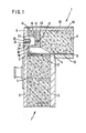
- Fig. 1 einen abgebrochen dargestellten Teil des Behälters und des Deckels in einem vertikalen Schnitt;
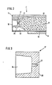
- Fig. 2 einen abgebrochen dargestellten Teil des Deckels in einem vertikalen Schnitt gemäß Fig. 1;
- Fig. 3 einen der im Deckel eingelassenen, die Aussparungen bildenden Einsätze in gegenüber den Fig. 1 und 2 vergrößertem Maßstab.
- Figure 1 shows a broken part of the container and the lid in a vertical section.
- FIG. 2 shows a part of the cover shown broken off in a vertical section according to FIG. 1;
- Fig. 3 one of the inserts in the lid, forming the recesses on an enlarged scale compared to Figs. 1 and 2.
Wie Fig. 1 erkennen läßt, besteht die Vorrichtung aus einem zylindrischen Behälter, dessen geschlossene Ummantelung 1 aus innen- und außenseitig mit Stahlblechen 2 und 3 verkleidetem Stahl-Beton 4 hergestellt ist. Mit den Stahlblechen 2 und 3, die als verlorene Schalung für den Stahl-Beton 4 dienen, ist eine Abdeckringscheibe 5 verschweißt, die mit der oberen Stirnfläche des die innenseitige Verkleidung bildenden Stahlblechs 2 bündig abschließt und vom die außenseitige Verkleidung bildenden Stahlblech 3 so überragt wird, daß der überragende Teil des Stahlblechs 3 einen Kragen 6 bildet.As can be seen in FIG. 1, the device consists of a cylindrical container, the closed casing 1 of which is made of steel and concrete 4 clad with
Eine stirnseitige Öffnung des Behälters ist durch einen Deckel 7 verschließbar, der gleichfalls aus StahlBeton 8 hergestellt ist und auf seinen beiden Stirnflächen mit Stahlblechscheiben 9 bzw. 10 sowie auf seiner Randfläche mit einem Stahlblechzylinder 11 verkleidet ist. Der Deckel 7 liegt mit einer Randfläche 12 der dem Behälterinnern zugewandten Stahlblechscheibe 9 auf der Abdeckringscheibe 5, während der Stahlblechzylinder 11 des Deckels 7 über seine volle Höhe von dem aus dem Stahlblech 3 gebildeten Kragen 6 seitlich abgedeckt wird. Auf der Unterseite der Stahlblechscheibe 9 ist eine Grundplatte 13 angeschweißt, die einen Durchmesser aufweist, der geringfügig größer ist als der Behälterinnendurchmesser und bis in eine Ausdrehung 14 im Randbereich des Stahlblechs 2 reicht. Auf der Oberseite der Stahlblechscheibe 10 ist eine Abdeckplatte 15 angeschweißt, die einen Durchmesser aufweist, der geringfügig größer ist als der Innendurchmesser des Kragens 6 und mit dessen Stirnfläche verschweißbar ist.An end opening of the container can be closed by a
In gleichmäßiger Verteilung über den Umfang des Deckels 7 sind im Stahlblechzylinder 11 Öffnungen 16 vorgesehen. An jeder dieser Öffnungen 16 ist ein radial ausgerichteter, mit dem Stahlblechzylinder 11 verschweißter Einsatz 17 angeschlossen, der über einen radialen Steg 18 zusätzlich mit der Stahlblechscheibe 9 verschweißt und im Stahl-Beton 8 des Deckels 7 eingegossen ist. Jeder Einsatz 17 weist eine zum Zentrum des Deckels 7 hin konisch verengte Aussparung 19 auf, deren Kegelwinkel im Ausführungsbeispiel etwa 11°, 25' beträgt. Koaxial zur Aussparung 19 ist im Boden 20 des Einsatzes 17 eine Gewindebohrung 21 vorgesehen.In a uniform distribution over the circumference of the
In einer der Anordnung der Einsätze 17 entsprechenden Anordnung sind mit den Öffnungen 16 im Stahlblechzylinder 11 fluchtende Durchbrüche 22 im Kragen 6 vorgesehen. Durch jeden Durchbruch 22 läßt sich ein konischer Zapfen 23, dessen Kegelwinkel mit dem der Aussparungen 19 übereinstimmt, eintreiben, wobei eine entsprechende Wandstärke des Kragens 6 sicherstellt, daß der Zapfen 23 durch die Laibung der Durchbrüche 22 eine sichere Führung erhält.In an arrangement corresponding to the arrangement of the
Beim Eintreiben der Zapfen 23 in die Aussparungen 19 wird der Deckel 7 mit der Randfläche 12 der Stahlblechsscheibe 9 gegen die Abdeckringscheibe 5 der Ummantelung 1 gepreßt und fest darauf gehalten.When the
Um ein unbeabsichtigtes Herausgleiten der Zapfen 23 aus den Aussparungen 19 auszuschließen, ist jeder Zapfen 23 mit einer durchgehenden koaxialen Bohrung 24 versehen, worin ein Gewindebolzen 25 in Form einer Inbusschraube einführbar und in die Gewindebohrung 21 im Boden 20 des Einsatzes 17 eindrehbar ist. Zur Sicherung des mit seinem Kopf 26 versenkt in der Bohrung 24 eingelassenen Gewindebolzens 25 kann schließlich noch ein Seegerring in den erweiterten Teil der Bohrung 24 eingesetzt oder aber der Kopf 26 mit dem Kragen 6 verschweißt werden. Die gleiche Wirkung läßt sich mit einem die Öffnung der Bohrung 24 ganz oder teilweise abdeckenden, gleichfalls am Kragen 6 verschweißten Plättchen erzielen, wenn der Kopf 26 in der Endstellung des Zapfens 23 bündig mit der Außenseite des Kragens 6 abschließt.To prevent the
Claims (5)
Applications Claiming Priority (2)
| Application Number | Priority Date | Filing Date | Title |
|---|---|---|---|
| DE3535420 | 1985-10-04 | ||
| DE19853535420 DE3535420C1 (en) | 1985-10-04 | 1985-10-04 | Transport and storage device for radioactive materials |
Publications (3)
| Publication Number | Publication Date |
|---|---|
| EP0218889A2 true EP0218889A2 (en) | 1987-04-22 |
| EP0218889A3 EP0218889A3 (en) | 1987-12-02 |
| EP0218889B1 EP0218889B1 (en) | 1990-05-09 |
Family
ID=6282726
Family Applications (1)
| Application Number | Title | Priority Date | Filing Date |
|---|---|---|---|
| EP19860112234 Expired - Lifetime EP0218889B1 (en) | 1985-10-04 | 1986-09-04 | Transport and storage device for radioactive materials |
Country Status (3)
| Country | Link |
|---|---|
| EP (1) | EP0218889B1 (en) |
| JP (1) | JPS6287897A (en) |
| DE (1) | DE3535420C1 (en) |
Families Citing this family (2)
| Publication number | Priority date | Publication date | Assignee | Title |
|---|---|---|---|---|
| JPH05144260A (en) * | 1991-11-26 | 1993-06-11 | Matsushita Graphic Commun Syst Inc | Image communication apparatus |
| JP5875384B2 (en) * | 2012-01-24 | 2016-03-02 | 太平洋セメント株式会社 | Radioactive waste storage container |
Citations (3)
| Publication number | Priority date | Publication date | Assignee | Title |
|---|---|---|---|---|
| FR2529372A3 (en) * | 1982-06-26 | 1983-12-30 | Kernforschungsz Karlsruhe | Drum for storing radioactive scrap - where cast iron or steel inner drum is placed in outer concrete drum, and both drums can be reopened if required |
| DE3331892A1 (en) * | 1983-09-03 | 1985-04-04 | Kernforschungsanlage Jülich GmbH, 5170 Jülich | TRANSPORT AND STORAGE CONTAINER FOR RADIOACTIVE MATERIAL |
| DE3516838A1 (en) * | 1985-05-10 | 1986-11-13 | Siempelkamp Gießerei GmbH & Co, 4150 Krefeld | Shipping cask and/or storage container for radioactive substances |
-
1985
- 1985-10-04 DE DE19853535420 patent/DE3535420C1/en not_active Expired
-
1986
- 1986-09-04 EP EP19860112234 patent/EP0218889B1/en not_active Expired - Lifetime
- 1986-10-02 JP JP23337286A patent/JPS6287897A/en active Pending
Patent Citations (3)
| Publication number | Priority date | Publication date | Assignee | Title |
|---|---|---|---|---|
| FR2529372A3 (en) * | 1982-06-26 | 1983-12-30 | Kernforschungsz Karlsruhe | Drum for storing radioactive scrap - where cast iron or steel inner drum is placed in outer concrete drum, and both drums can be reopened if required |
| DE3331892A1 (en) * | 1983-09-03 | 1985-04-04 | Kernforschungsanlage Jülich GmbH, 5170 Jülich | TRANSPORT AND STORAGE CONTAINER FOR RADIOACTIVE MATERIAL |
| DE3516838A1 (en) * | 1985-05-10 | 1986-11-13 | Siempelkamp Gießerei GmbH & Co, 4150 Krefeld | Shipping cask and/or storage container for radioactive substances |
Also Published As
| Publication number | Publication date |
|---|---|
| EP0218889A3 (en) | 1987-12-02 |
| EP0218889B1 (en) | 1990-05-09 |
| JPS6287897A (en) | 1987-04-22 |
| DE3535420C1 (en) | 1986-12-18 |
Similar Documents
| Publication | Publication Date | Title |
|---|---|---|
| DE2753206C2 (en) | Magnetic key operated coupling device for a rotary handle | |
| DE3105347C3 (en) | Fitting to be fastened to a wall with two fastening end pieces running essentially perpendicular to the wall and associated bases which can be screwed onto the wall | |
| EP0175211B1 (en) | Socket spanner actuated and arrested by a sash lock | |
| EP0218889B1 (en) | Transport and storage device for radioactive materials | |
| DE2241222A1 (en) | LID FRAME FOR ROAD BUTCH | |
| CH676731A5 (en) | ||
| DE2756511A1 (en) | LOCKING DEVICE FOR MANHOLE COVERS OF STREET ENTRANCE CHAMBERS, COMPOSING OF A REMOVABLE LID AND A FIXED BASE | |
| DE2612265C3 (en) | Anchor bolts | |
| DE10002993A1 (en) | Stackable fixing device for formwork purposes, with spring elements between cover part and gripping magnet body | |
| EP0953687B1 (en) | Height levelling device between a manhole collar and a roadway surface and implementation of the device in a roadway construction | |
| DE8401123U1 (en) | Form-fitting dowels for concrete | |
| EP1024304B1 (en) | Threaded insert for plastic parts | |
| DE3814365C2 (en) | Coupling, especially for diamond core bit with shaft tube and pipe thread connection | |
| DE3202107C2 (en) | Fixing device for an L-shaped strike plate | |
| DE2300883C3 (en) | Device for connecting two frame parts of a pallet attachment frame | |
| DE3534134C1 (en) | Transport and storage containers for radioactive materials | |
| DE4204828A1 (en) | Fastening device to form mounting point on esp. watercraft - consists of pocket-shaped holder with external thread in hull, and holder element | |
| DE3227512A1 (en) | Consumable shielding container for radioactive waste | |
| DE2145066C3 (en) | Manhole cover for a manhole | |
| EP0118002A2 (en) | Marking carrier for transport anchors | |
| DE3416035C2 (en) | ||
| DE1400886C (en) | Dowels for a layer composite panel | |
| DE3728071A1 (en) | POCKET LOCK | |
| WO2002027128A9 (en) | Door hinge plate | |
| DD301841A9 (en) | Device for closing and pealing objects |
Legal Events
| Date | Code | Title | Description |
|---|---|---|---|
| PUAI | Public reference made under article 153(3) epc to a published international application that has entered the european phase |
Free format text: ORIGINAL CODE: 0009012 |
|
| AK | Designated contracting states |
Kind code of ref document: A2 Designated state(s): BE CH FR GB IT LI LU NL SE |
|
| PUAL | Search report despatched |
Free format text: ORIGINAL CODE: 0009013 |
|
| AK | Designated contracting states |
Kind code of ref document: A3 Designated state(s): BE CH FR GB IT LI LU NL SE |
|
| 17P | Request for examination filed |
Effective date: 19871210 |
|
| 17Q | First examination report despatched |
Effective date: 19890919 |
|
| RAP3 | Party data changed (applicant data changed or rights of an application transferred) |
Owner name: FORSCHUNGSZENTRUM JUELICH GMBH |
|
| GRAA | (expected) grant |
Free format text: ORIGINAL CODE: 0009210 |
|
| AK | Designated contracting states |
Kind code of ref document: B1 Designated state(s): BE CH FR GB IT LI LU NL SE |
|
| ET | Fr: translation filed | ||
| ITF | It: translation for a ep patent filed |
Owner name: STUDIO JAUMANN |
|
| GBT | Gb: translation of ep patent filed (gb section 77(6)(a)/1977) | ||
| PLBE | No opposition filed within time limit |
Free format text: ORIGINAL CODE: 0009261 |
|
| STAA | Information on the status of an ep patent application or granted ep patent |
Free format text: STATUS: NO OPPOSITION FILED WITHIN TIME LIMIT |
|
| 26N | No opposition filed | ||
| ITTA | It: last paid annual fee | ||
| EPTA | Lu: last paid annual fee | ||
| EAL | Se: european patent in force in sweden |
Ref document number: 86112234.9 |
|
| PGFP | Annual fee paid to national office [announced via postgrant information from national office to epo] |
Ref country code: GB Payment date: 20000821 Year of fee payment: 15 |
|
| PGFP | Annual fee paid to national office [announced via postgrant information from national office to epo] |
Ref country code: FR Payment date: 20000918 Year of fee payment: 15 |
|
| PGFP | Annual fee paid to national office [announced via postgrant information from national office to epo] |
Ref country code: SE Payment date: 20000921 Year of fee payment: 15 |
|
| PGFP | Annual fee paid to national office [announced via postgrant information from national office to epo] |
Ref country code: LU Payment date: 20000922 Year of fee payment: 15 Ref country code: CH Payment date: 20000922 Year of fee payment: 15 Ref country code: BE Payment date: 20000922 Year of fee payment: 15 |
|
| PGFP | Annual fee paid to national office [announced via postgrant information from national office to epo] |
Ref country code: NL Payment date: 20000926 Year of fee payment: 15 |
|
| PG25 | Lapsed in a contracting state [announced via postgrant information from national office to epo] |
Ref country code: LU Free format text: LAPSE BECAUSE OF NON-PAYMENT OF DUE FEES Effective date: 20010904 Ref country code: GB Free format text: LAPSE BECAUSE OF NON-PAYMENT OF DUE FEES Effective date: 20010904 |
|
| PG25 | Lapsed in a contracting state [announced via postgrant information from national office to epo] |
Ref country code: SE Free format text: LAPSE BECAUSE OF NON-PAYMENT OF DUE FEES Effective date: 20010905 |
|
| PG25 | Lapsed in a contracting state [announced via postgrant information from national office to epo] |
Ref country code: LI Free format text: LAPSE BECAUSE OF NON-PAYMENT OF DUE FEES Effective date: 20010930 Ref country code: CH Free format text: LAPSE BECAUSE OF NON-PAYMENT OF DUE FEES Effective date: 20010930 Ref country code: BE Free format text: LAPSE BECAUSE OF NON-PAYMENT OF DUE FEES Effective date: 20010930 |
|
| BERE | Be: lapsed |
Owner name: FORSCHUNGSZENTRUM JULICH G.M.B.H. Effective date: 20010930 |
|
| PG25 | Lapsed in a contracting state [announced via postgrant information from national office to epo] |
Ref country code: NL Free format text: LAPSE BECAUSE OF NON-PAYMENT OF DUE FEES Effective date: 20020401 |
|
| EUG | Se: european patent has lapsed |
Ref document number: 86112234.9 |
|
| REG | Reference to a national code |
Ref country code: CH Ref legal event code: PL |
|
| PG25 | Lapsed in a contracting state [announced via postgrant information from national office to epo] |
Ref country code: FR Free format text: LAPSE BECAUSE OF NON-PAYMENT OF DUE FEES Effective date: 20020531 |
|
| NLV4 | Nl: lapsed or anulled due to non-payment of the annual fee |
Effective date: 20020401 |
|
| REG | Reference to a national code |
Ref country code: FR Ref legal event code: ST |
|
| NLV4 | Nl: lapsed or anulled due to non-payment of the annual fee |
Effective date: 20020401 |
|
| PG25 | Lapsed in a contracting state [announced via postgrant information from national office to epo] |
Ref country code: IT Free format text: LAPSE BECAUSE OF NON-PAYMENT OF DUE FEES;WARNING: LAPSES OF ITALIAN PATENTS WITH EFFECTIVE DATE BEFORE 2007 MAY HAVE OCCURRED AT ANY TIME BEFORE 2007. THE CORRECT EFFECTIVE DATE MAY BE DIFFERENT FROM THE ONE RECORDED. Effective date: 20050904 |