EP0218671B1 - An air-jet mill for fine and/or cryogenic milling and surface treatment of preferably hard, elastic and/or thermoplastic materials - Google Patents
An air-jet mill for fine and/or cryogenic milling and surface treatment of preferably hard, elastic and/or thermoplastic materials Download PDFInfo
- Publication number
- EP0218671B1 EP0218671B1 EP86902464A EP86902464A EP0218671B1 EP 0218671 B1 EP0218671 B1 EP 0218671B1 EP 86902464 A EP86902464 A EP 86902464A EP 86902464 A EP86902464 A EP 86902464A EP 0218671 B1 EP0218671 B1 EP 0218671B1
- Authority
- EP
- European Patent Office
- Prior art keywords
- grinding
- nozzles
- pregrinding
- air
- chamber
- Prior art date
- Legal status (The legal status is an assumption and is not a legal conclusion. Google has not performed a legal analysis and makes no representation as to the accuracy of the status listed.)
- Expired - Lifetime
Links
Images

Classifications
-
- B—PERFORMING OPERATIONS; TRANSPORTING
- B02—CRUSHING, PULVERISING, OR DISINTEGRATING; PREPARATORY TREATMENT OF GRAIN FOR MILLING
- B02C—CRUSHING, PULVERISING, OR DISINTEGRATING IN GENERAL; MILLING GRAIN
- B02C19/00—Other disintegrating devices or methods
- B02C19/06—Jet mills
- B02C19/065—Jet mills of the opposed-jet type
-
- B—PERFORMING OPERATIONS; TRANSPORTING
- B02—CRUSHING, PULVERISING, OR DISINTEGRATING; PREPARATORY TREATMENT OF GRAIN FOR MILLING
- B02C—CRUSHING, PULVERISING, OR DISINTEGRATING IN GENERAL; MILLING GRAIN
- B02C19/00—Other disintegrating devices or methods
- B02C19/06—Jet mills
- B02C19/061—Jet mills of the cylindrical type
Definitions
- the invention relates to an energy-saving inside-sizing air-jet mill having a pregrinding chamber, for the fine grinding preferably of various carbides, silicates, oxides, ores, pigments or elastic materials, as well as for the surface treatment and/or cryogenic grinding of the same according to the first part of claim 1 (US-A-3559895).
- Air-jet mills known according to the present state of the art can be traced back to five basic types.
- the first type is characterised in that grinding takes place by the impinging of material accelerated to high speed by a nozzle on a so-called anvil.
- This facility provides adequate grinding but, because of its high specific energy consumption, its operation is not economic and the lining is subject to considerable wear, highly contaminating the ground product thereby.
- the third air-jet mill is the one which has been used most.
- the essence of its operation is that grinding takes place in the discus-shaped grinding chamber due to the effect of gas outflowing from peripheral jet pipes.
- the gas jets first contact a circle in the outer third or half of the grinding area. Material to be ground enters the grinding space in a vertical plane crossing the tangent to this circle, however, at angles of 60° to the vertical passing through the top of the grinding space.
- the grains exceeding a predetermined size are circulating along this tangential circle, the smaller ones, that is the ground end product, discharge from the facility through an obstructing dam and the coarser grains, due to the effect of the outflowing gas from the peripheral nozzles, collide with each other and circulate until their size is reduced below the required level.
- the operation of the facility does not match the above theoretical conditions yet the type is widely used as a unit presenting the best efficiency.
- the fluid bed air-jet-mills could be included in the fifth type (e.g. DE 3140294 C2).
- the frequency of collision of the particles, and thus the efficiency of grinding is increased by the use of four nozzles located in the bottom of a large container and of larger diameter than the previous ones which were operated opposite each other.
- the nozzles operate to fluidize the entire amount of material in the container causing the finer grains, already ready-ground, to be lead off, these having previously been passed through a rotating sizer in the top section of the container. Meanwhile, the coarser fraction slides back down the wall of the container for repeated grinding.
- the facility exhibits good grinding and sizing efficiency but is not suitable for fine grinding, below 10 p. This is partly because of the short path length of the particles (high density) which means that they have little impact energy and partly because the speed of rotation of the revolving part of the sizer which determines the fineness of the end product cannot be increased beyond a certain limit. Further disadvantages of this design are that the revolving part of the sizer is exposed to high wear and, due to the high overpressure of the grinding space, material supply can be carried out only by the use of an involved sluice system.
- the invention aims to develop an air-jet mill capable of fine grinding very hard, or elastic and/ or thermoplastic materials, to below 10 um, which is energy-saving, does not contain any movable parts, and exhibits high resistance to abrasion.
- the invention provides an air-jet mill for fine grinding, surface treatment and/or cooled grinding of particulate material, the mill including: a vertical-axis, generally-circular grinding space; pregrinding chambers connected to the grinding space by at least three blow ducts for introducing preground material tangentially into the grinding space; peripheral grinding nozzles in the grinding space for supplying fluid to the chamber to create a high-speed vortical flow therein; an axial discharge stub for discharging ground product from the grinding space; and a sizer within the grinding space for determining the size of particles in the discharged product, characterised in that: there are at least three pregrinding chambers each connected by a respective blow duct to the grinding space and each having a respective injection nozzle coaxial with its blow duct for supplying it with material to be preground and at least two confluent nozzles for supplying opposing fluid flows to the pregrinding chamber; the grinding space is also connected to each pregrinding chamber by a respective material-return duct for returning
- the sizing performance of such a mill is sharp and the sizer does not swallow a major portion of the comminution energy.
- the invention is based on the perception of the following:
- material feed to the grinding space takes place in a horizontal plane and in a tangential direction.
- wear of the lining of the grinding space occurring with the micronizer types can be reduced.
- the number and positioning of the peripheral nozzles in the grinding chamber should be selected such that every nozzle performs the same grinding work: it is expedient to charge material into the grinding space after every second nozzle. For instance, if six peripheral nozzles are applied and three tangentially-set blow ducts are used, the grinding performance can be increased three-fold according to tests made.
- the coarser fraction from the grinding space is refed to each pregrinding chamber through a respective return duct by the effect of vacuum generated in the charging duct.
- the material-charging nozzles are connected to the pregrinding chamber, the latter being provided with a wear resistant lining, where two or more nozzles set at 90°-180° angles to each other and/or shifted in the plane are injecting the material confluently. If more than two confluent nozzles are used, two are preferably arranged to perform material feed but the remaining ones are arranged to decrease wear by reducing the probability of particles impacting with the wall of the chamber.
- the injection nozzles are also suitable for introducing fresh material to be ground, surface-treatment materials and/or a coolant into the system according to the particular grinding technology required; i.e. with the nozzles properly adjusted, vacuum would be generated in the feed orifice causing the coolant or any reagent to get sucked in.
- the injection nozzles coaxial with the respective blow ducts; the injection nozzles exhibit the highest pressure in the system and are suitable for accelerating the preground material to an adequate velocity, a multiple of the velocity of sound, in spite of the vortices generated by the confluent nozzles, thus enabling the preground material to reach the grinding space.
- each pregrinding chamber there are four nozzles connected to each pregrinding chamber in tangential directions.
- the flow in each chamber is perpendicular to the plane of the main grinding space and the gas jets generate a vortex by contacting a circle of comparatively small radius.
- two of the four nozzles which are nearly-horizontal, shoot together the material to be ground while the other two, nearly-vertical nozzles, deliver gas or air to the system.
- the latter may be linked to containers of reagents or coolant.
- the blow ducts are connected tangentially at three points to the grinding space where the six peripheral nozzles rotatable around their vertical axes are located symmetrically.
- the grinding chamber is connected by means of material-return ducts to each of the pregrinding chambers in order to return the coarse fraction thereto.
- the inner sizer is designed to be symmetrical with the axis of the grinding space the former consisting of a surface area of a hyperboloid of revolution and an adjustable curb of blades having the same axis as the discharge stub for the ground product.
- each pregrinding chamber is cylindrical, with its axis vertical, and has two confluent nozzles set at an angle within the range 150°-180° to each other and another injection nozzle placed on the axis of the blow duct. All three may be connected to respective charging funnels.
- the material to be ground flows in the required quantity by gravity from the storage container onto the charging dish/disc feeder, the latter being shaken eccentrically.
- a uniform stream of material flows from the disc feeder into material-charging funnels located along the edge of the dish.
- three pregrinding chambers 1 defining pregrinding spaces 5 with wear-resistant linings are connected to a generally-circular, vertical-axis grinding space 2 defined in a casing 16 of the air-jet mill.
- Two confluent nozzles 7, located in nozzle casings 6, and an injecting nozzle 8 are linked to each pregrinding space 5 through charging ducts 9 formed with Laval-profiles.
- Each pregrinder 1 is connected to the grinding space 2 by a blow duct 3 tangential to the grinding space 2 and by a material-return duct 4.
- Six peripheral grinding nozzles 10 are located symmetrically in the grinding space 2 and can be swivelled in the horizontal plane by rotation of an angle setter 11.
- an angle setter 11 In the grinding space 2 there is a wear-resistant lining 12 and a centrally-located curb of angularly-adjustable blades 13.
- a gear 15 and a stub 14 for setting the blade angle are provided.
- a discharge stub 17 is located on the axis of the casing 16. Material-charging stubs 18 and air-inlet stubs 19 are also provided on the facility.
- Figure 3 shows another potential mode of construction.
- the pregrinding chamber is of simpler design; the axes of each pair of confluent nozzles 7 located in the nozzle casings 6 are set at 150-180°, preferably 150°, angles to each other and to the respective blow duct 3.
- the inclinations of the confluent nozzles should be selected in dependence on the radius of the pregrinding space such that the component of the velocity of preground material is directed to the grinding space.
- the development of the grinding casing 2, the peripheral grinding nozzles 10 and the curb of adjustable blades 13 as well as charging of material are identical to those outlined above.
- the material-charging system is shown in Figure 4.
- the material storing hopper 20 is equipped with adjustable louvres 21.
- the material flows from the hopper onto a disc feeder 23 shaken by an eccentrically operating unit 22 such that the material is spread uniformly and distributed into charging funnels 24 each connected to a material- supply stub 18.
- the main advantage of the air-jet mill of the invention lies in the fact that, in contrast to the facilities known so far, it is capable of producing grain fractions less than 10 11m in size. Moreover, it can be used for the cryogenic grinding of thermoplastic materials and, if required, for applying surface-treatment materials contemporarily with grinding.
- a further advantage of the facility lies in the excellent utilization of energy which is largely a consequence of the novel shaping of the inner sizer. The utilization efficiency of the grinding energy is one-and-a-half- fold that of a similar conventional facility.
- Particular advantage lies in the fact that the unit does not include any movable parts which could be exposed to severe wear and the constructional parts, the linings of the pregrinders which are exposed to the greatest wear can easily be replaced at little expense.
Landscapes
- Engineering & Computer Science (AREA)
- Food Science & Technology (AREA)
- Disintegrating Or Milling (AREA)
Abstract
Description
- The invention relates to an energy-saving inside-sizing air-jet mill having a pregrinding chamber, for the fine grinding preferably of various carbides, silicates, oxides, ores, pigments or elastic materials, as well as for the surface treatment and/or cryogenic grinding of the same according to the first part of claim 1 (US-A-3559895).
- Air-jet mills known according to the present state of the art can be traced back to five basic types. The first type is characterised in that grinding takes place by the impinging of material accelerated to high speed by a nozzle on a so-called anvil. This facility provides adequate grinding but, because of its high specific energy consumption, its operation is not economic and the lining is subject to considerable wear, highly contaminating the ground product thereby.
- In order to eliminate this contaminating effect linings of the same basic material as the material to be ground are often used. The best known version of this type now in use is the Vortex- system mill which is provided with an outer sizer for determining the size of particles discharged in the end product, a ceramic lining and an anvil. Another type of air-jet mill which is widely used is the so-called Majec mill. Here, comminution takes place by the autogenous grinding effect of grains impacting against each other by the acceleration generated by two nozzles facing one another. This operation, however, exhibits energy losses and thus very poor comminution efficiency. The nozzles can carry comparatively small amounts of grains and vortices occur due to the effect of the opposing air jets, thus reducing the number of grain collisions. Known examples of this type are: DE-A-2543691 and DE-A-2523471.
- The third air-jet mill, the so-called Micronizer type, is the one which has been used most. The essence of its operation is that grinding takes place in the discus-shaped grinding chamber due to the effect of gas outflowing from peripheral jet pipes. The gas jets first contact a circle in the outer third or half of the grinding area. Material to be ground enters the grinding space in a vertical plane crossing the tangent to this circle, however, at angles of 60° to the vertical passing through the top of the grinding space.
- According to the theory of the designers, the grains exceeding a predetermined size are circulating along this tangential circle, the smaller ones, that is the ground end product, discharge from the facility through an obstructing dam and the coarser grains, due to the effect of the outflowing gas from the peripheral nozzles, collide with each other and circulate until their size is reduced below the required level. Under actual working conditions the operation of the facility does not match the above theoretical conditions yet the type is widely used as a unit presenting the best efficiency. There are several patented inventions relating to developments in the above, e.g. US 18586, SF-33960, DE 3201778 C1. These technical solutions represent combinations of the double-jet mill, the anvil-type mill and the micronizer in which either the coarse product is refed to the grinding space or it is attempted, with little success, to improve the fineness of grinding by application of an anvil-type pregrinder.
- Therefore, up to now, the unchanged, basic type provided with some kind of liner is most frequently used in the industry.
- With the fourth type of air-jet mill an attempt was made to increase the mill output by a method which did not cause the shortening of the path of free movement of particles.
- In favour of this, the volume of the grinding space and the number of nozzles were increased, thereby increasing the output of the mill relative to its unit volume, but the efficiency of energy utilization was reduced and the extent of wear increased. This type of mill has been called a Jet-0-Mizer or Reductionizer. Aiming at the reduction of wear the design of the Double-Impact-Mill appeared on the market. In the return branch of the upper part of the mill a so-called directional- change-sizer and further grinding nozzles have been applied in some cases. These types of mill did not succeed in achieving a grain size of 1 pm.
- The fluid bed air-jet-mills could be included in the fifth type (e.g. DE 3140294 C2). In these the frequency of collision of the particles, and thus the efficiency of grinding, is increased by the use of four nozzles located in the bottom of a large container and of larger diameter than the previous ones which were operated opposite each other. The nozzles operate to fluidize the entire amount of material in the container causing the finer grains, already ready-ground, to be lead off, these having previously been passed through a rotating sizer in the top section of the container. Meanwhile, the coarser fraction slides back down the wall of the container for repeated grinding.
- The facility exhibits good grinding and sizing efficiency but is not suitable for fine grinding, below 10 p. This is partly because of the short path length of the particles (high density) which means that they have little impact energy and partly because the speed of rotation of the revolving part of the sizer which determines the fineness of the end product cannot be increased beyond a certain limit. Further disadvantages of this design are that the revolving part of the sizer is exposed to high wear and, due to the high overpressure of the grinding space, material supply can be carried out only by the use of an involved sluice system.
- From a knowledge of the types of air-jet facilities adopted so far, it can be established that the efficiency is favourable if particles possess high energies and there is a high probability of impacting. As the number of solid particles is increased, the probability of impacting may be increased but the free path length required for the particles to be accelerated shortens and, consequently, the impact energy also diminishes. A compromise is thus required in the design of air-jet facilities: whether to increase the free path length and make the ground product finer along with diminishing performance of the mill, or to increase the number of impacts which results in a coarser product but improves the grinding efficiency and performance of the mill.
- The invention aims to develop an air-jet mill capable of fine grinding very hard, or elastic and/ or thermoplastic materials, to below 10 um, which is energy-saving, does not contain any movable parts, and exhibits high resistance to abrasion.
- Accordingly the invention provides an air-jet mill for fine grinding, surface treatment and/or cooled grinding of particulate material, the mill including: a vertical-axis, generally-circular grinding space; pregrinding chambers connected to the grinding space by at least three blow ducts for introducing preground material tangentially into the grinding space; peripheral grinding nozzles in the grinding space for supplying fluid to the chamber to create a high-speed vortical flow therein; an axial discharge stub for discharging ground product from the grinding space; and a sizer within the grinding space for determining the size of particles in the discharged product, characterised in that: there are at least three pregrinding chambers each connected by a respective blow duct to the grinding space and each having a respective injection nozzle coaxial with its blow duct for supplying it with material to be preground and at least two confluent nozzles for supplying opposing fluid flows to the pregrinding chamber; the grinding space is also connected to each pregrinding chamber by a respective material-return duct for returning particles larger than the size selected by the sizer to the pregrinding chambers; there are twice as many peripheral grinding nozzles as there are blow ducts, the grinding nozzles being arranged symmetrically in a circle and directed so as to reduce the impact of the particulate material with the wall of the grinding space; and the sizer comprises a curb of blades arranged coaxially within the grinding space and cooperating with the wall of the grinding chamber to effect the sizing, the grinding-chamber wall having a lower surface which rises along a circular arc and an upper surface comprising a hyperboloid.
- It can be arranged that the sizing performance of such a mill is sharp and the sizer does not swallow a major portion of the comminution energy.
- The invention is based on the perception of the following:
- - grinding efficiency can be improved considerably by: the adoption of pregrinding; increasing the number and arrangement of nozzles adequately; recirculating a coarser fraction into the pregrinding chamber,
- - if an adequate number of peripheral nozzles is provided in the grinding space it can be arranged for all the nozzles to perform the same grinding work,
- - by eliminating moving parts and charging material in a horizontal plane in tangential direction, minimum abrasion wear can be achieved and even this can be confined to the easily- replaceable elements of the pregrinding chamber,
- - wear of the pregrinding chambers can be reduced considerably by providing each pregrinding chamber with as many auxiliary nozzles as there are confluently-jetting main nozzles in order to divert material from the wall of the pregrinding chamber,
- - by the development of a new profile lining element for the grinding chamber and the adoption of a curb of blades of adjustable blade angle, very sharp inner sizing can be obtained within the grain limits 0.1-100 p, without any input of additional energy, by the utilization of energy left after grinding,
- - by adequate axial adjustment of the pregrinding chamber nozzles, vacuum is generated in the charging ducts enabling the charging and refeeding of materials to be ground as well as the introduction of surface treatment materials and/or coolants into the system. This way the facility is also suitable for surface treatment or grinding of heat-sensitive and elastic materials,
- - setting of the angle of the peripheral nozzles in the grinding space (diverting the material from the wall) reduces the number of impacts on the wall thus enabling an optimum adjustment of the movement of the material.
- With the construction of the air-jet mill in accordance with the invention, material feed to the grinding space takes place in a horizontal plane and in a tangential direction. Thus, besides good grinding efficiency, wear of the lining of the grinding space occurring with the micronizer types can be reduced. The use of pregrinding chambers, giving a smaller size of feed material, considerably improves the grinding efficiency. The number and positioning of the peripheral nozzles in the grinding chamber should be selected such that every nozzle performs the same grinding work: it is expedient to charge material into the grinding space after every second nozzle. For instance, if six peripheral nozzles are applied and three tangentially-set blow ducts are used, the grinding performance can be increased three-fold according to tests made.
- In order further to improve the grinding efficiency, the coarser fraction from the grinding space is refed to each pregrinding chamber through a respective return duct by the effect of vacuum generated in the charging duct. The material-charging nozzles are connected to the pregrinding chamber, the latter being provided with a wear resistant lining, where two or more nozzles set at 90°-180° angles to each other and/or shifted in the plane are injecting the material confluently. If more than two confluent nozzles are used, two are preferably arranged to perform material feed but the remaining ones are arranged to decrease wear by reducing the probability of particles impacting with the wall of the chamber.
- The arrangement of nozzles, according to the invention, just by giving rise to generation of vortices, i.e. by increasing the number of particle impacts, results in a very good grinding effect in the pregrinding chamber. The injection nozzles are also suitable for introducing fresh material to be ground, surface-treatment materials and/or a coolant into the system according to the particular grinding technology required; i.e. with the nozzles properly adjusted, vacuum would be generated in the feed orifice causing the coolant or any reagent to get sucked in.
- Access of preground material into the grinding space is made possible by the injection nozzles coaxial with the respective blow ducts; the injection nozzles exhibit the highest pressure in the system and are suitable for accelerating the preground material to an adequate velocity, a multiple of the velocity of sound, in spite of the vortices generated by the confluent nozzles, thus enabling the preground material to reach the grinding space.
- On investigating the relation between comminution efficiency and pressure, it has been established that efficiency improves slightly up to a pressure of 9 bar, then increases rapidly in the range 9-15 bar and finally, depending on the material, severe agglomeration can take place in the range 15-25 bar, thus reducing the efficiency of comminution.
- In one embodiment of the air-jet mill of the invention, there are four nozzles connected to each pregrinding chamber in tangential directions. The flow in each chamber is perpendicular to the plane of the main grinding space and the gas jets generate a vortex by contacting a circle of comparatively small radius. With this solution, two of the four nozzles, which are nearly-horizontal, shoot together the material to be ground while the other two, nearly-vertical nozzles, deliver gas or air to the system. The latter may be linked to containers of reagents or coolant.
- The blow ducts are connected tangentially at three points to the grinding space where the six peripheral nozzles rotatable around their vertical axes are located symmetrically. The grinding chamber is connected by means of material-return ducts to each of the pregrinding chambers in order to return the coarse fraction thereto. The inner sizer is designed to be symmetrical with the axis of the grinding space the former consisting of a surface area of a hyperboloid of revolution and an adjustable curb of blades having the same axis as the discharge stub for the ground product.
- Another potential alternative design of the air-jet mill of the invention differs from the one outlined above in the mode of development of the pregrinding chamber. With this solution, each pregrinding chamber is cylindrical, with its axis vertical, and has two confluent nozzles set at an angle within the range 150°-180° to each other and another injection nozzle placed on the axis of the blow duct. All three may be connected to respective charging funnels.
- With either kind of design of the air-jet mill, the material to be ground flows in the required quantity by gravity from the storage container onto the charging dish/disc feeder, the latter being shaken eccentrically. A uniform stream of material flows from the disc feeder into material-charging funnels located along the edge of the dish.
- The invention will be explained, by way of example, with reference to the attached drawings, which are as follows.
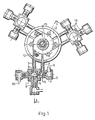
- Figure 1 is a cross-section of one possible construction of the air-jet mill of the invention.
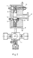
- Figure 2 is a section drawn along the line I-I indicated in Figure 1.
- Figure 3 is a section of another possible construction.
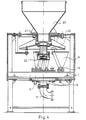
- Figure 4 is a longitudinal section of a material charging system of the air-jet mill of the invention.
- In the construction shown as an example in Figures 1 and 2, three
pregrinding chambers 1 definingpregrinding spaces 5 with wear-resistant linings are connected to a generally-circular, vertical-axis grinding space 2 defined in acasing 16 of the air-jet mill. Twoconfluent nozzles 7, located innozzle casings 6, and an injecting nozzle 8 are linked to eachpregrinding space 5 through charging ducts 9 formed with Laval-profiles. Eachpregrinder 1 is connected to the grindingspace 2 by ablow duct 3 tangential to the grindingspace 2 and by a material-return duct 4. - Six peripheral grinding
nozzles 10 are located symmetrically in the grindingspace 2 and can be swivelled in the horizontal plane by rotation of anangle setter 11. In the grindingspace 2 there is a wear-resistant lining 12 and a centrally-located curb of angularly-adjustable blades 13. Agear 15 and astub 14 for setting the blade angle are provided. As can be seen from the drawings, adischarge stub 17 is located on the axis of thecasing 16. Material-chargingstubs 18 and air-inlet stubs 19 are also provided on the facility. - Figure 3 shows another potential mode of construction. In this case, the pregrinding chamber is of simpler design; the axes of each pair of
confluent nozzles 7 located in thenozzle casings 6 are set at 150-180°, preferably 150°, angles to each other and to therespective blow duct 3. The inclinations of the confluent nozzles should be selected in dependence on the radius of the pregrinding space such that the component of the velocity of preground material is directed to the grinding space. The development of the grindingcasing 2, the peripheral grindingnozzles 10 and the curb ofadjustable blades 13 as well as charging of material are identical to those outlined above. - The material-charging system is shown in Figure 4. The
material storing hopper 20 is equipped withadjustable louvres 21. The material flows from the hopper onto adisc feeder 23 shaken by aneccentrically operating unit 22 such that the material is spread uniformly and distributed into charging funnels 24 each connected to a material-supply stub 18. - The main advantage of the air-jet mill of the invention lies in the fact that, in contrast to the facilities known so far, it is capable of producing grain fractions less than 10 11m in size. Moreover, it can be used for the cryogenic grinding of thermoplastic materials and, if required, for applying surface-treatment materials contemporarily with grinding. A further advantage of the facility lies in the excellent utilization of energy which is largely a consequence of the novel shaping of the inner sizer. The utilization efficiency of the grinding energy is one-and-a-half- fold that of a similar conventional facility. Particular advantage lies in the fact that the unit does not include any movable parts which could be exposed to severe wear and the constructional parts, the linings of the pregrinders which are exposed to the greatest wear can easily be replaced at little expense.
Claims (7)
Priority Applications (1)
| Application Number | Priority Date | Filing Date | Title |
|---|---|---|---|
| AT86902464T ATE52949T1 (en) | 1985-04-03 | 1986-04-03 | JET MILL FOR FINING AND/OR GRINDING AT LOW TEMPERATURE AND SURFACE TREATMENT OF PREFERABLY HARD, ELASTIC AND/OR THERMOPLASTIC MATERIALS. |
Applications Claiming Priority (2)
| Application Number | Priority Date | Filing Date | Title |
|---|---|---|---|
| HU851272A HU196323B (en) | 1985-04-03 | 1985-04-03 | Air-jet mill for fine and/or cryogenic grinding, surface treating advantageously hard, elastic and/or thermoplastic matters |
| HU127285 | 1985-04-03 |
Publications (2)
| Publication Number | Publication Date |
|---|---|
| EP0218671A1 EP0218671A1 (en) | 1987-04-22 |
| EP0218671B1 true EP0218671B1 (en) | 1990-05-23 |
Family
ID=10953640
Family Applications (1)
| Application Number | Title | Priority Date | Filing Date |
|---|---|---|---|
| EP86902464A Expired - Lifetime EP0218671B1 (en) | 1985-04-03 | 1986-04-03 | An air-jet mill for fine and/or cryogenic milling and surface treatment of preferably hard, elastic and/or thermoplastic materials |
Country Status (8)
| Country | Link |
|---|---|
| US (1) | US4807815A (en) |
| EP (1) | EP0218671B1 (en) |
| JP (1) | JPS62502953A (en) |
| DE (1) | DE3671391D1 (en) |
| FI (1) | FI82616C (en) |
| HU (1) | HU196323B (en) |
| SU (1) | SU1582977A3 (en) |
| WO (1) | WO1986005717A1 (en) |
Families Citing this family (10)
| Publication number | Priority date | Publication date | Assignee | Title |
|---|---|---|---|---|
| GB8720904D0 (en) * | 1987-09-05 | 1987-10-14 | Tioxide Group Plc | Mill |
| DE3833830A1 (en) * | 1988-10-05 | 1990-04-12 | Messer Griesheim Gmbh | METHOD AND DEVICE FOR COLD GRINDING |
| US5542613A (en) * | 1992-12-10 | 1996-08-06 | Nied; Roland | Process for impact crushing of solid particles |
| US5637344A (en) * | 1995-10-20 | 1997-06-10 | Hershey Foods Corporation | Chocolate flavored hard candy |
| WO2005018811A1 (en) * | 2003-08-26 | 2005-03-03 | Aleksandr Kurochka | Material breaking device |
| US20080026955A1 (en) * | 2006-07-25 | 2008-01-31 | Halliburton Energy Services, Inc. | Degradable particulates and associated methods |
| US9114114B2 (en) | 2007-06-21 | 2015-08-25 | Mars, Inc. | Edible products having a high cocoa polyphenol content and improved flavor and the milled cocoa extracts used therein |
| TW201446329A (en) | 2013-03-11 | 2014-12-16 | 道達爾研究及技術弗呂公司 | Process for producing fine, morphologically optimized particles using jet mill, jet mill for use in such process and particles produced |
| CN106113326A (en) * | 2016-08-03 | 2016-11-16 | 平湖市永光机械配件有限公司 | A kind of plain grinding joint of fine pulverizer |
| CN112403659A (en) * | 2020-11-23 | 2021-02-26 | 西安建筑科技大学 | Nozzle ring movable vane anti-abrasion cover of medium-speed coal mill |
Family Cites Families (9)
| Publication number | Priority date | Publication date | Assignee | Title |
|---|---|---|---|---|
| AT135713B (en) * | 1932-02-12 | 1933-12-11 | Paul Anger | Device for sifting in air jet impact mills. |
| US3229918A (en) * | 1963-06-05 | 1966-01-18 | Helme Products Inc | Fluid grinding mill with interchange-able liners |
| US3559895A (en) * | 1968-02-20 | 1971-02-02 | Edwin F Fay | Apparatus for and method of comminuting solid materials |
| CH584069A5 (en) * | 1974-05-08 | 1977-01-31 | Micro Mecinazione Sa | |
| FR2311588A1 (en) * | 1975-05-23 | 1976-12-17 | Inst Francais Du Petrole | Venturi device for disintegrating agglomerated powders - for rapid, complete sepn. of e.g. polyfluorocarbon polymers |
| DE2523471C2 (en) * | 1975-05-27 | 1983-03-17 | Gosudarstvennyj Vsesojuznyj naučno-issledovatel'skij institut cementnoj promyšlennosti Niicement, Moskva | Treatment plant for bulk goods |
| DE2543691C2 (en) * | 1975-09-30 | 1984-01-19 | Gosudarstvennyj Vsesojuznyj naučno-issledovatel'skij institut cementnoj promyšlennosti Niicement, Moskva | Jet mill |
| DE3140294C2 (en) * | 1981-10-10 | 1983-11-17 | Alpine Ag, 8900 Augsburg | Method and device for separating a material mixture into components of different grindability |
| US4504017A (en) * | 1983-06-08 | 1985-03-12 | Norandy, Incorporated | Apparatus for comminuting materials to extremely fine size using a circulating stream jet mill and a discrete but interconnected and interdependent rotating anvil-jet impact mill |
-
1985
- 1985-04-03 HU HU851272A patent/HU196323B/en not_active IP Right Cessation
-
1986
- 1986-04-03 DE DE8686902464T patent/DE3671391D1/en not_active Expired - Fee Related
- 1986-04-03 JP JP61502242A patent/JPS62502953A/en active Pending
- 1986-04-03 EP EP86902464A patent/EP0218671B1/en not_active Expired - Lifetime
- 1986-04-03 WO PCT/HU1986/000020 patent/WO1986005717A1/en not_active Ceased
- 1986-04-03 US US07/002,695 patent/US4807815A/en not_active Expired - Fee Related
- 1986-12-01 FI FI864882A patent/FI82616C/en not_active IP Right Cessation
- 1986-12-02 SU SU864028585A patent/SU1582977A3/en active
Also Published As
| Publication number | Publication date |
|---|---|
| WO1986005717A1 (en) | 1986-10-09 |
| HU196323B (en) | 1988-11-28 |
| SU1582977A3 (en) | 1990-07-30 |
| FI864882A7 (en) | 1986-12-01 |
| FI864882A0 (en) | 1986-12-01 |
| FI82616C (en) | 1991-04-10 |
| JPS62502953A (en) | 1987-11-26 |
| FI82616B (en) | 1990-12-31 |
| US4807815A (en) | 1989-02-28 |
| EP0218671A1 (en) | 1987-04-22 |
| DE3671391D1 (en) | 1990-06-28 |
| HUT42351A (en) | 1987-07-28 |
Similar Documents
| Publication | Publication Date | Title |
|---|---|---|
| EP0488637B1 (en) | A fluidized bed jet mill | |
| JP4427285B2 (en) | Double odd bell-shaped opening nozzle device for fluidized bed jet mill | |
| KR930001984A (en) | Impingement airflow pulverizer, fine powder production apparatus and toner production method | |
| US3559895A (en) | Apparatus for and method of comminuting solid materials | |
| KR920009291B1 (en) | Impingement air pulverizer and pulverization method | |
| US4807815A (en) | Air-jet mill and associated pregrinding apparatus for comminuating solid materials | |
| FI74222B (en) | KVARNHUS FOER TRYCKAMMARKVARN. | |
| US5628464A (en) | Fluidized bed jet mill nozzle and processes therewith | |
| US4875629A (en) | Particle pulverizer injection nozzle | |
| US5683039A (en) | Laval nozzle with central feed tube and particle comminution processes thereof | |
| CA1269354A (en) | Air-jet mill for fine and/or cryogenic milling and surface treatment of preferably hard, elastic and/or thermoplastic materials | |
| JP4738770B2 (en) | Grinding device and grinding method | |
| CN86104423A (en) | To hard partially, flexible and/or thermoplastic material carries out meticulous and/or low-temperature grinding and surface-treated airslide disintegrating mill | |
| JPS58143853A (en) | Supersonic jet mill | |
| JPS6316980B2 (en) | ||
| US5547135A (en) | Micromilling apparatus | |
| JPH02152559A (en) | Grinding and coating equipment | |
| AU2016213757B2 (en) | Rotary mill | |
| SU893252A1 (en) | Percussion-action mill | |
| KR0180107B1 (en) | Grinding method of fine powder using compressive fluid and apparatus | |
| KR0167010B1 (en) | Grinding method of fine powder using compressive fluid and apparatus | |
| JPH07289933A (en) | Crusher | |
| CN116033969A (en) | jet mill | |
| JPH078829A (en) | Fine pulverizer | |
| JPH08103684A (en) | Collision airflow crusher |
Legal Events
| Date | Code | Title | Description |
|---|---|---|---|
| PUAI | Public reference made under article 153(3) epc to a published international application that has entered the european phase |
Free format text: ORIGINAL CODE: 0009012 |
|
| 17P | Request for examination filed |
Effective date: 19861211 |
|
| AK | Designated contracting states |
Kind code of ref document: A1 Designated state(s): AT BE CH DE FR GB IT LI LU NL SE |
|
| 17Q | First examination report despatched |
Effective date: 19880831 |
|
| GRAA | (expected) grant |
Free format text: ORIGINAL CODE: 0009210 |
|
| AK | Designated contracting states |
Kind code of ref document: B1 Designated state(s): AT BE CH DE FR GB IT LI LU NL SE |
|
| REF | Corresponds to: |
Ref document number: 52949 Country of ref document: AT Date of ref document: 19900615 Kind code of ref document: T |
|
| ITF | It: translation for a ep patent filed | ||
| ET | Fr: translation filed | ||
| REF | Corresponds to: |
Ref document number: 3671391 Country of ref document: DE Date of ref document: 19900628 |
|
| PLBE | No opposition filed within time limit |
Free format text: ORIGINAL CODE: 0009261 |
|
| STAA | Information on the status of an ep patent application or granted ep patent |
Free format text: STATUS: NO OPPOSITION FILED WITHIN TIME LIMIT |
|
| 26N | No opposition filed | ||
| PGFP | Annual fee paid to national office [announced via postgrant information from national office to epo] |
Ref country code: LU Payment date: 19920326 Year of fee payment: 7 |
|
| PGFP | Annual fee paid to national office [announced via postgrant information from national office to epo] |
Ref country code: GB Payment date: 19920327 Year of fee payment: 7 Ref country code: CH Payment date: 19920327 Year of fee payment: 7 Ref country code: BE Payment date: 19920327 Year of fee payment: 7 |
|
| PGFP | Annual fee paid to national office [announced via postgrant information from national office to epo] |
Ref country code: FR Payment date: 19920331 Year of fee payment: 7 |
|
| PGFP | Annual fee paid to national office [announced via postgrant information from national office to epo] |
Ref country code: SE Payment date: 19920416 Year of fee payment: 7 |
|
| PGFP | Annual fee paid to national office [announced via postgrant information from national office to epo] |
Ref country code: DE Payment date: 19920429 Year of fee payment: 7 |
|
| ITTA | It: last paid annual fee | ||
| PGFP | Annual fee paid to national office [announced via postgrant information from national office to epo] |
Ref country code: AT Payment date: 19920430 Year of fee payment: 7 Ref country code: NL Payment date: 19920430 Year of fee payment: 7 |
|
| EPTA | Lu: last paid annual fee | ||
| PG25 | Lapsed in a contracting state [announced via postgrant information from national office to epo] |
Ref country code: LU Free format text: LAPSE BECAUSE OF NON-PAYMENT OF DUE FEES Effective date: 19930403 Ref country code: GB Effective date: 19930403 Ref country code: AT Effective date: 19930403 |
|
| PG25 | Lapsed in a contracting state [announced via postgrant information from national office to epo] |
Ref country code: SE Effective date: 19930404 |
|
| PG25 | Lapsed in a contracting state [announced via postgrant information from national office to epo] |
Ref country code: LI Effective date: 19930430 Ref country code: CH Effective date: 19930430 Ref country code: BE Effective date: 19930430 |
|
| BERE | Be: lapsed |
Owner name: MAGYAR ALUMINIUMIPARI TROSZT Effective date: 19930430 |
|
| PG25 | Lapsed in a contracting state [announced via postgrant information from national office to epo] |
Ref country code: NL Effective date: 19931101 |
|
| GBPC | Gb: european patent ceased through non-payment of renewal fee |
Effective date: 19930403 |
|
| NLV4 | Nl: lapsed or anulled due to non-payment of the annual fee | ||
| PG25 | Lapsed in a contracting state [announced via postgrant information from national office to epo] |
Ref country code: FR Effective date: 19931229 |
|
| REG | Reference to a national code |
Ref country code: CH Ref legal event code: PL |
|
| PG25 | Lapsed in a contracting state [announced via postgrant information from national office to epo] |
Ref country code: DE Effective date: 19940101 |
|
| REG | Reference to a national code |
Ref country code: FR Ref legal event code: ST |
|
| EUG | Se: european patent has lapsed |
Ref document number: 86902464.6 Effective date: 19931110 |
|
| PG25 | Lapsed in a contracting state [announced via postgrant information from national office to epo] |
Ref country code: IT Free format text: LAPSE BECAUSE OF NON-PAYMENT OF DUE FEES Effective date: 20050403 |