EP0218521A1 - Mehrphasiger elektrischer Motor mit variabler Reluktanz - Google Patents
Mehrphasiger elektrischer Motor mit variabler Reluktanz Download PDFInfo
- Publication number
- EP0218521A1 EP0218521A1 EP86402111A EP86402111A EP0218521A1 EP 0218521 A1 EP0218521 A1 EP 0218521A1 EP 86402111 A EP86402111 A EP 86402111A EP 86402111 A EP86402111 A EP 86402111A EP 0218521 A1 EP0218521 A1 EP 0218521A1
- Authority
- EP
- European Patent Office
- Prior art keywords
- blades
- studs
- electric motor
- core
- stator
- Prior art date
- Legal status (The legal status is an assumption and is not a legal conclusion. Google has not performed a legal analysis and makes no representation as to the accuracy of the status listed.)
- Granted
Links
Images




Classifications
-
- H—ELECTRICITY
- H02—GENERATION; CONVERSION OR DISTRIBUTION OF ELECTRIC POWER
- H02K—DYNAMO-ELECTRIC MACHINES
- H02K37/00—Motors with rotor rotating step by step and without interrupter or commutator driven by the rotor, e.g. stepping motors
- H02K37/10—Motors with rotor rotating step by step and without interrupter or commutator driven by the rotor, e.g. stepping motors of permanent magnet type
- H02K37/12—Motors with rotor rotating step by step and without interrupter or commutator driven by the rotor, e.g. stepping motors of permanent magnet type with stationary armatures and rotating magnets
- H02K37/125—Magnet axially facing armature
-
- H—ELECTRICITY
- H02—GENERATION; CONVERSION OR DISTRIBUTION OF ELECTRIC POWER
- H02K—DYNAMO-ELECTRIC MACHINES
- H02K21/00—Synchronous motors having permanent magnets; Synchronous generators having permanent magnets
- H02K21/12—Synchronous motors having permanent magnets; Synchronous generators having permanent magnets with stationary armatures and rotating magnets
- H02K21/24—Synchronous motors having permanent magnets; Synchronous generators having permanent magnets with stationary armatures and rotating magnets with magnets axially facing the armatures, e.g. hub-type cycle dynamos
-
- H—ELECTRICITY
- H02—GENERATION; CONVERSION OR DISTRIBUTION OF ELECTRIC POWER
- H02K—DYNAMO-ELECTRIC MACHINES
- H02K21/00—Synchronous motors having permanent magnets; Synchronous generators having permanent magnets
- H02K21/38—Synchronous motors having permanent magnets; Synchronous generators having permanent magnets with rotating flux distributors, and armatures and magnets both stationary
-
- H—ELECTRICITY
- H02—GENERATION; CONVERSION OR DISTRIBUTION OF ELECTRIC POWER
- H02K—DYNAMO-ELECTRIC MACHINES
- H02K37/00—Motors with rotor rotating step by step and without interrupter or commutator driven by the rotor, e.g. stepping motors
- H02K37/02—Motors with rotor rotating step by step and without interrupter or commutator driven by the rotor, e.g. stepping motors of variable reluctance type
- H02K37/08—Motors with rotor rotating step by step and without interrupter or commutator driven by the rotor, e.g. stepping motors of variable reluctance type with rotors axially facing the stators
-
- H—ELECTRICITY
- H02—GENERATION; CONVERSION OR DISTRIBUTION OF ELECTRIC POWER
- H02K—DYNAMO-ELECTRIC MACHINES
- H02K37/00—Motors with rotor rotating step by step and without interrupter or commutator driven by the rotor, e.g. stepping motors
- H02K37/10—Motors with rotor rotating step by step and without interrupter or commutator driven by the rotor, e.g. stepping motors of permanent magnet type
- H02K37/20—Motors with rotor rotating step by step and without interrupter or commutator driven by the rotor, e.g. stepping motors of permanent magnet type with rotating flux distributors, the armatures and magnets both being stationary
-
- H—ELECTRICITY
- H02—GENERATION; CONVERSION OR DISTRIBUTION OF ELECTRIC POWER
- H02K—DYNAMO-ELECTRIC MACHINES
- H02K41/00—Propulsion systems in which a rigid body is moved along a path due to dynamo-electric interaction between the body and a magnetic field travelling along the path
- H02K41/02—Linear motors; Sectional motors
- H02K41/03—Synchronous motors; Motors moving step by step; Reluctance motors
Definitions
- the present invention relates to polyphase variable reluctance electric motors comprising a movable ferromagnetic core in a stator provided with m windings (m being at least equal to 3) allowing each to create a magnetic flux in the direction of movement of the movable core and a source allowing the windings to be supplied with a phase shift of 2w / m, each winding being associated with a clean ferromagnetic circuit closing by the core.
- m being at least equal to 3
- the invention proposes an electric motor of the type defined above, the core of which comprises several thin ferromagnetic blades, parallel to the direction of movement, and each divided in the longitudinal direction into studs with a determined pitch p and in that the ferromagnetic circuit of each winding also includes several thin blades alternating with those of the core and also split into studs at the same pitch p as that of the studs of the core.
- the studs of the stator advantageously comprise permanent magnets.
- the stator pads are, for example, made up of a ferromagnetic strip and two longitudinal reverse magnet magnets placed on either side of the strip. Each pad is separated from each other by a ferromagnetic part which can have the same length in the direction of movement of the core mobile than the length of the ferromagnetic strip of the stud itself.
- Successive magnets belonging to two different pads are of alternating magnetization.
- the blades of the mobile element are carried by a common core of non-ferromagnetic material, for example stainless steel, constituting a pusher; the windings are each associated with a set of ferromagnetic blades of the stator, the blades of a set having an offset of p / m with respect to another set.
- each blade is made up of alternating ferromagnetic metal and non-magnetic metal. It is possible in particular to use an alternation of tracks made of silicon steel, or failing that made of soft iron, and of stainless steel.
- the manufacture of identical blades can be carried out by brazing, under vacuum, at a temperature of the order of 550 * , alternating pads made of silicon steel and ferromagnetic materials. Then the bar thus formed is cut longitudinally to give blades whose thickness can easily be reduced to about 1 mm.
- stator blades comprise permanent magnets
- manufacture of the stator blades may be carried out from a non-magnetic steel profile on which two magnetic steel plates are affixed on either side.
- Grooves are then machined in which the magnets are stuck with their alternating magnetization.
- the windings can be designed to be traversed by alternating current only (in the case of a rotary actuator).
- the coils can also be divided into two groups, one traversed by direct current, the other by alternating current or even the two currents can be superimposed in the same windings.
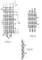
- FIG 1 schematically shows the ferromagnetic elements, capable of relative displacement, of a linear actuator constituting a particular embodiment of an electric motor with variable reluctance according to the invention.
- the stator of this actuator comprises a large number of parallel stator blades 10, secured to each other by support means 12 of non-ferromagnetic material. Only three blades 10 are shown in Fig.1 but in practice the number will be significantly higher.
- Each of the blades 10 is split into independent pads 14 distributed at regular intervals, with a repetition step p. Insulating zones 16 will generally be provided between the pads to improve the mechanical strength of the blade and these areas will be shorter than the pads in the direction of movement.
- the movable part of the actuator consists of a core also having several parallel blades 18, nested with the stator blades 10 and also made up of separate pads 20, distributed with the same pitch p as the pads 14.
- the blades 18 are joined by means not shown and their length must be greater than that of the blades 10, the excess length fixing the possible amplitude of movement of the blades.
- the clearances between adjacent blades 18 and 10 are as small as possible.
- the assembly consisting of the stator and the core presents two positions of equilibrium in a B field directed in the direction of the blades.
- One of them shown in Fig.2, is a position in conjunction with unstable equilibrium and corresponds to the maximum reluctance of the magnetic circuit traversed by the lines of force of a field created by an external winding not shown.
- the second equilibrium position (Fig. 3) is stable and corresponds to a staggered arrangement of the studs 14 and 20.
- the magnetic induction tends to bring the studs into the maximum flow position shown in Fig.3: the blades 18 of the core then move until the studs are in the staggered or opposing position shown in Fig.3. If the induction field B is then cut, the blade remains in the new position.
- n greater than or equal to 3, of successive modules such as module 22 of the stator (see Fig .1) which has just been described.
- the different modules can be placed in series or in parallel.
- Fig.1 has been shown a fraction of a second module 24 of the stator, in series with the first.
- the winding creation windings will be supplied by excitation currents phase-shifted by T / n, T being the period of the supply current.
- the pads 14 of two successive stators will be shifted by p / n.
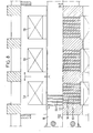
- Fig.4 shows a possible constitution of a three-phase linear actuator corresponding to the diagram in Fig.1. For this reason, the members of Fig.4 already shown in Fig.1 are designated by the same reference number.
- the movable core of the actuator comprises a non-magnetic core 15, for example made of stainless steel, which carries two series of blades 18, each series having for example five blades.
- the blades have a small thickness, advantageously of the order of a millimeter. They are made of magnetic material and permanently fixed to the core 15, for example by embedding and silver soldering.
- the blades are cut into regularly spaced pads 20, the pads of the two series facing each other.
- the distribution pitch of the pads 20 (length along the direction of movement increased by the interval between two successive pads) will generally be between 0.5 and 4 times the thickness of the blade. It can be seen that the studs thus take the form of thin strips.
- the intervals between successive lamellae can be filled with insulation.
- the stator comprises two parts symmetrical with respect to the axis of the pusher with three modules 22, 24, and 26. These modules being identical, only the module 22 will be described.
- each part of the stator comprises a support piece 28 of non-magnetic material on which the corresponding studs 14 are brazed.
- the length of the supports 28 determines the useful area of the actuator.
- the blades provided in the three useful zones are separated by additional blades 30 also fixed but not split into studs. These blades 30 make it possible to complete the magnetic circuit of a carcass 32 on which are wound windings 34, 36 and 38 belonging respectively to modules 22, 24, and 26. All the sheets constituting the carcass 32 are made of ferromagnetic material.
- stator plates of module 24 are offset by p / n with respect to those of module 22 and module 26.
- the windings 34, 36 and 38 are associated with a supply circuit which may include a source 40 of direct current and a chopper 42 supplying the windings with cyclic pulses at regular intervals.
- This chopper can be controlled by a core displacement sensor.
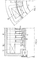
- Fig.5 shows a single inductor winding 34 carried by the closing circuit of the excitation field, constituted by a carcass 32 made of stacked sheets. These sheets have a thickness corresponding to that of the blades and nest in the uncut blades 30 belonging to the stator to ensure better circulation of the flux. The blades 30 therefore have a height greater than those of the blades 14. Finally, the carcass is mounted in a frame (not shown) carrying guide rails for the core.
- Figs 6 and 7 show a possible constitution of such a machine.
- the blades then take the form of parallel metal discs.
- Fig.6 shows such blades 10 belonging to the stator, alternating with blades 18, also disc-shaped, belonging to the core, formed by a rotor.
- the return circuit is also constituted by a carcass 32.
- Fig.7 shows the shape taken by the field lines B when the pads of the blades are in conjunction in the circumferential development zone 1 where the reluctance variations occur. This arrangement, like the previous one, can be modified to obtain a Vernier effect.
- the lamellae are separated by non-magnetic zones formed by air. If from an electromagnetic point of view we arrive at a completely satisfactory structure, manufacturing is complex.
- a linear actuator constituting a variant, the stator and rotor blades of which have a simpler constitution to manufacture.
- FIGs 8 and 9 where the bodies corresponding to those of Figures 4 to 6 are designated by the same reference numbers, as the core blades are formed by an alternation of ferromagnetic lamellae (in silicon iron for example) and nonmagnetic lamellae (in stainless steel for example) which replace the intervals occupied by air in the previous embodiment.
- the ferromagnetic lamellae will generally have a length in the direction of movement approximately twice the length of the nonmagnetic lamellae.
- the thickness of the strips will generally be of the same order as the length of the non-magnetic strips.
- the manufacture of the blades can be as follows: an alternating stack of ferromagnetic and non-magnetic plates is made. All the plates are joined together under vacuum while remaining below the Curie point, for example by silver brazing or electron beam welding. The stack is then cut to the desired thickness for the blades.
- the assembly of the blades can then be carried out in an absolutely conventional manner, by clamping between stirrups.
- the stator blades can have the same constitution as those which have just been described, by providing spacers having an increased length in the direction of movement to correspond to the interval between the coils. These spacers are made of ferromagnetic material and must have a size such that they allow the flow of flux during operation without reaching saturation.
- This same constitution of the blades can be used in the case of a rotary machine.
- the intervals separating the blades shown in FIG. 7, will be occupied by a non-ferromagnetic metallic material such as stainless steel and all the lamellae will be joined in the form of an annular disc having alternating sectors, for example made of ferrosilicon and stainless steel.
- This arrangement like the previous one, can be modified to obtain a Vernier effect.
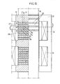
- FIG. 12 shows a linear actuator according to the invention, the studs 14 of a blade 10 of the stator comprising longitudinal magnets 19, 21 of alternating magnetization framing a central ferromagnetic strip 17.
- Each pad is separated from the next by a part 23 which is itself feromagnetic.
- Magnets 31 and 19a, 21a and 19b, etc. successive belonging to two different pads of the stator are of alternating magnetization.
- the pitch R of the studs 14 of the stator is the same as the pitch p of the studs 20 of the movable element, the blades 18 of which can be identical to those of the variable reluctance actuator without magnet.
- the rest of the device can be similar to that of the actuator without magnet, with the possibility of reducing the windings 34, 36 to two in the case of a two-phase machine.
- the length in the direction of movement of each stud of the pusher is equal to the length in the direction of movement of each stud of the stator.
Landscapes
- Engineering & Computer Science (AREA)
- Power Engineering (AREA)
- Physics & Mathematics (AREA)
- Chemical & Material Sciences (AREA)
- Combustion & Propulsion (AREA)
- Electromagnetism (AREA)
- Linear Motors (AREA)
- Iron Core Of Rotating Electric Machines (AREA)
Priority Applications (1)
| Application Number | Priority Date | Filing Date | Title |
|---|---|---|---|
| AT86402111T ATE61700T1 (de) | 1985-09-27 | 1986-09-26 | Mehrphasiger elektrischer motor mit variabler reluktanz. |
Applications Claiming Priority (4)
| Application Number | Priority Date | Filing Date | Title |
|---|---|---|---|
| FR8514365 | 1985-09-27 | ||
| FR8514365A FR2588132A1 (fr) | 1985-09-27 | 1985-09-27 | Machine synchrone polyentrefers a aimants permanents |
| FR8514363A FR2588133A1 (fr) | 1985-09-27 | 1985-09-27 | Moteur electrique polyphase a reluctance variable |
| FR8514363 | 1985-09-27 |
Publications (2)
| Publication Number | Publication Date |
|---|---|
| EP0218521A1 true EP0218521A1 (de) | 1987-04-15 |
| EP0218521B1 EP0218521B1 (de) | 1991-03-13 |
Family
ID=26224732
Family Applications (1)
| Application Number | Title | Priority Date | Filing Date |
|---|---|---|---|
| EP86402111A Expired - Lifetime EP0218521B1 (de) | 1985-09-27 | 1986-09-26 | Mehrphasiger elektrischer Motor mit variabler Reluktanz |
Country Status (4)
| Country | Link |
|---|---|
| US (1) | US4864169A (de) |
| EP (1) | EP0218521B1 (de) |
| CA (1) | CA1271802A (de) |
| DE (1) | DE3678087D1 (de) |
Cited By (2)
| Publication number | Priority date | Publication date | Assignee | Title |
|---|---|---|---|---|
| EP0373987A1 (de) * | 1988-11-22 | 1990-06-20 | Shinko Electric Co. Ltd. | Betätigungsgerät mit starker magnetischer Schiebekraft |
| FR2743217A1 (fr) * | 1995-12-29 | 1997-07-04 | France Etat | Accelarateur ou actionneur lineaire |
Families Citing this family (22)
| Publication number | Priority date | Publication date | Assignee | Title |
|---|---|---|---|---|
| US5536471A (en) | 1992-03-27 | 1996-07-16 | Abbott Laboratories | Syringe with bubble flushing |
| US5646049A (en) | 1992-03-27 | 1997-07-08 | Abbott Laboratories | Scheduling operation of an automated analytical system |
| US5610069A (en) | 1992-03-27 | 1997-03-11 | Abbott Laboratories | Apparatus and method for washing clinical apparatus |
| US5507410A (en) | 1992-03-27 | 1996-04-16 | Abbott Laboratories | Meia cartridge feeder |
| US5960160A (en) | 1992-03-27 | 1999-09-28 | Abbott Laboratories | Liquid heater assembly with a pair temperature controlled electric heating elements and a coiled tube therebetween |
| US6190617B1 (en) | 1992-03-27 | 2001-02-20 | Abbott Laboratories | Sample container segment assembly |
| US5578494A (en) | 1992-03-27 | 1996-11-26 | Abbott Laboratories | Cap actuator for opening and closing a container |
| US5635364A (en) | 1992-03-27 | 1997-06-03 | Abbott Laboratories | Assay verification control for an automated analytical system |
| US5605665A (en) | 1992-03-27 | 1997-02-25 | Abbott Laboratories | Reaction vessel |
| US5575978A (en) | 1992-03-27 | 1996-11-19 | Abbott Laboratories | Sample container segment assembly |
| US5376313A (en) | 1992-03-27 | 1994-12-27 | Abbott Laboratories | Injection molding a plastic assay cuvette having low birefringence |
| US5627522A (en) | 1992-03-27 | 1997-05-06 | Abbott Laboratories | Automated liquid level sensing system |
| US5540890A (en) | 1992-03-27 | 1996-07-30 | Abbott Laboratories | Capped-closure for a container |
| USD349861S (en) | 1992-07-20 | 1994-08-23 | Abbott Laboratories | Automated analytical instrument |
| US6279728B1 (en) * | 1998-07-20 | 2001-08-28 | Norbert G Jung | Electro-magnetic conveyor |
| DE19838378A1 (de) * | 1998-08-24 | 2000-03-02 | Magnet Motor Gmbh | Elektrische Maschine mit Dauermagneten |
| FR2841704B1 (fr) * | 2002-07-01 | 2004-08-27 | Centre Nat Rech Scient | Actionneur ou generateur lineaire a tiges |
| US7218019B2 (en) * | 2002-12-06 | 2007-05-15 | Foster-Miller, Inc | Linear reluctance motor |
| US8004127B2 (en) * | 2002-12-06 | 2011-08-23 | Foster-Miller, Inc. | Rotary reluctance motor |
| DE102004045992A1 (de) * | 2004-09-22 | 2006-04-06 | Siemens Ag | Elektrische Maschine |
| FR2903823B1 (fr) * | 2006-07-12 | 2008-09-05 | Messier Dowty Sa | Element actif de machine electromagnetique, procede de fabrication d'un tel element actif, et machine electromagnetique comportant un tel element actif. |
| US20110254386A1 (en) * | 2010-04-19 | 2011-10-20 | Liu Kuo-Shen | Power generator with high power-to-volume ratio |
Citations (6)
| Publication number | Priority date | Publication date | Assignee | Title |
|---|---|---|---|---|
| GB137255A (en) * | 1919-02-14 | 1920-01-08 | Charles Leslie Walker | Improvements in and connected with electro-magnetic step-by-step and like mechanism |
| CH196052A (de) * | 1936-06-29 | 1938-02-28 | Jakob Bohli | Mit einem Stator und einem Rotor versehene magnetelektrische Maschine. |
| US2797346A (en) * | 1954-07-16 | 1957-06-25 | Agnes Jones Ranseen | Electric motors |
| FR2152529A1 (de) * | 1971-09-14 | 1973-04-27 | Zeiss Jena Veb Carl | |
| FR2259472A1 (en) * | 1974-01-30 | 1975-08-22 | Valroger Pierre | Polyphase linear motor for high-speed traction - has field coils fed with polyphase current controlled by thyristors |
| US3992641A (en) * | 1974-11-22 | 1976-11-16 | Westinghouse Electric Corporation | Polyphase disc reluctance motor |
Family Cites Families (5)
| Publication number | Priority date | Publication date | Assignee | Title |
|---|---|---|---|---|
| US3225228A (en) * | 1963-10-10 | 1965-12-21 | John L Roshala | Linear magnetic drive system |
| FR1592065A (de) * | 1967-01-25 | 1970-05-11 | ||
| DE2623234A1 (de) * | 1976-05-24 | 1977-12-01 | Alberto Kling | Elektromagnetische antriebsvorrichtung |
| SU625291A1 (ru) * | 1977-03-09 | 1978-09-25 | Пермское Высшее Военное Командное Училище | Линейный шаговый электродвинатель |
| SE457043B (sv) * | 1985-04-29 | 1988-11-21 | Facit Ab | Linjaer stegmotor |
-
1986
- 1986-09-25 US US06/911,457 patent/US4864169A/en not_active Expired - Fee Related
- 1986-09-26 CA CA000519189A patent/CA1271802A/fr not_active Expired - Lifetime
- 1986-09-26 EP EP86402111A patent/EP0218521B1/de not_active Expired - Lifetime
- 1986-09-26 DE DE8686402111T patent/DE3678087D1/de not_active Expired - Lifetime
Patent Citations (6)
| Publication number | Priority date | Publication date | Assignee | Title |
|---|---|---|---|---|
| GB137255A (en) * | 1919-02-14 | 1920-01-08 | Charles Leslie Walker | Improvements in and connected with electro-magnetic step-by-step and like mechanism |
| CH196052A (de) * | 1936-06-29 | 1938-02-28 | Jakob Bohli | Mit einem Stator und einem Rotor versehene magnetelektrische Maschine. |
| US2797346A (en) * | 1954-07-16 | 1957-06-25 | Agnes Jones Ranseen | Electric motors |
| FR2152529A1 (de) * | 1971-09-14 | 1973-04-27 | Zeiss Jena Veb Carl | |
| FR2259472A1 (en) * | 1974-01-30 | 1975-08-22 | Valroger Pierre | Polyphase linear motor for high-speed traction - has field coils fed with polyphase current controlled by thyristors |
| US3992641A (en) * | 1974-11-22 | 1976-11-16 | Westinghouse Electric Corporation | Polyphase disc reluctance motor |
Non-Patent Citations (3)
| Title |
|---|
| PATENT ABSTRACTS OF JAPAN, vol. 5, no. 51 (E-51)[723], 10 avril 1981; & JP-A-56 003 570 (YOKOGAWA DENKI SEISAKUSHO K.K.) 14-01-1981 * |
| PATENT ABSTRACTS OF JAPAN, vol. 7, no. 222 (E-201)[1367], 4 octobre 1983; & JP-A-58 112 454 (KOUKUU UCHIYUU GIJUTSU KENKYUSHO) 04-07-1983 * |
| SOVIET INVENTIONS ILLUSTRATED, semaine B28, 22 août 1979, Derwent Publications Ltd., Londres, GB; & SU-A-625291 (BYKOV) 00-03-1977 * |
Cited By (4)
| Publication number | Priority date | Publication date | Assignee | Title |
|---|---|---|---|---|
| EP0373987A1 (de) * | 1988-11-22 | 1990-06-20 | Shinko Electric Co. Ltd. | Betätigungsgerät mit starker magnetischer Schiebekraft |
| FR2743217A1 (fr) * | 1995-12-29 | 1997-07-04 | France Etat | Accelarateur ou actionneur lineaire |
| EP0783202A1 (de) * | 1995-12-29 | 1997-07-09 | ETAT FRANCAIS représenté par le DELEGUE GENERAL pour L'ARMEMENT | Beschleuniger für Linearantrieb |
| US5818177A (en) * | 1995-12-29 | 1998-10-06 | Etat Francais Represente Par La Delegue General Pour L'armement | Variable-reluctance synchronous electric linear actuator |
Also Published As
| Publication number | Publication date |
|---|---|
| DE3678087D1 (de) | 1991-04-18 |
| CA1271802A (fr) | 1990-07-17 |
| US4864169A (en) | 1989-09-05 |
| EP0218521B1 (de) | 1991-03-13 |
Similar Documents
| Publication | Publication Date | Title |
|---|---|---|
| EP0218521B1 (de) | Mehrphasiger elektrischer Motor mit variabler Reluktanz | |
| EP0974185B1 (de) | Verbesserter linearantrieb | |
| EP0158935B1 (de) | Elekrodynamische Verniermaschine | |
| FR2688105A1 (fr) | Actionneur rotatif electromagnetique monophase de course entre 60 et 120 degres. | |
| EP1236263B1 (de) | Reluktanz-motor/-generator wird durch eine wicklung im luftspalt erregt | |
| FR2519483A1 (fr) | Machine synchrone a rotor a aimants permanents | |
| FR2606951A1 (fr) | Moteur a aimants | |
| EP2878071B1 (de) | Wicklung für ein statorelement eines permanentmagnetmotors oder generators mit mindestens einem einkomponentigen starren glied und herstellungsverfahren dafür | |
| FR2684180A1 (fr) | Capteur de position angulaire absolue a reluctance variable. | |
| EP0866539A1 (de) | Elektrische Rotationsmaschine mit Wicklungserregung, Permanentmagneterregung oder überlagerter Erregung | |
| WO2009083898A1 (fr) | Moteur electrique de manoeuvre d'un element d'occultation ou de protection solaire dans un batiment | |
| EP0790695A1 (de) | Hybride, dynamoelektrische Maschine mit variabler Reluktanz und Herstellungs- und Berechnungsverfahren | |
| FR2957208A1 (fr) | Machine electrique polydiscoide polyphasee a aimants. | |
| EP0218522A1 (de) | Dauermagnetische Synchronmaschine mit mehreren Luftspalten | |
| FR2727174A1 (fr) | Palier magnetique a noyau de bobine rapporte | |
| EP0312464A1 (de) | Elektrische Maschine insbesondere mit radialen Luftspalten | |
| FR2588133A1 (fr) | Moteur electrique polyphase a reluctance variable | |
| EP1518314B1 (de) | Mit stangen versehener aktuator oder lineargenerator | |
| FR2625048A1 (fr) | Moteur electrique a haut rendement et a faible ondulation de couple | |
| WO2014122374A1 (fr) | Moteur ou génératrice électromagnétique polyentrefers à aimants permanents et élément à bobinage sans fer | |
| EP0871284B1 (de) | X-Y Kreuztisch zur Verstellung von Lasten mit hoher Genauigkeit und sehr hoher Dynamik | |
| EP0783202B1 (de) | Beschleuniger für Linearantrieb | |
| FR2846482A1 (fr) | Rotor pour machine electrique tournante a double excitation equipe de plots magnetiques formes chacun d'un element independant et machine electrique tournante a double excitation equipee de ce rotor | |
| FR2588131A1 (fr) | Machine electrique tournante a reluctance variable polyentrefers | |
| FR2606225A1 (fr) | Actionneur electromagnetique a deux entrefers |
Legal Events
| Date | Code | Title | Description |
|---|---|---|---|
| PUAI | Public reference made under article 153(3) epc to a published international application that has entered the european phase |
Free format text: ORIGINAL CODE: 0009012 |
|
| AK | Designated contracting states |
Kind code of ref document: A1 Designated state(s): AT BE CH DE FR GB IT LI LU NL SE |
|
| 17P | Request for examination filed |
Effective date: 19870624 |
|
| 17Q | First examination report despatched |
Effective date: 19891218 |
|
| GRAA | (expected) grant |
Free format text: ORIGINAL CODE: 0009210 |
|
| AK | Designated contracting states |
Kind code of ref document: B1 Designated state(s): AT BE CH DE FR GB IT LI LU NL SE |
|
| REF | Corresponds to: |
Ref document number: 61700 Country of ref document: AT Date of ref document: 19910315 Kind code of ref document: T |
|
| GBT | Gb: translation of ep patent filed (gb section 77(6)(a)/1977) | ||
| REF | Corresponds to: |
Ref document number: 3678087 Country of ref document: DE Date of ref document: 19910418 |
|
| ITF | It: translation for a ep patent filed | ||
| PGFP | Annual fee paid to national office [announced via postgrant information from national office to epo] |
Ref country code: AT Payment date: 19910830 Year of fee payment: 6 |
|
| PGFP | Annual fee paid to national office [announced via postgrant information from national office to epo] |
Ref country code: FR Payment date: 19910909 Year of fee payment: 6 |
|
| PGFP | Annual fee paid to national office [announced via postgrant information from national office to epo] |
Ref country code: CH Payment date: 19910912 Year of fee payment: 6 |
|
| PGFP | Annual fee paid to national office [announced via postgrant information from national office to epo] |
Ref country code: LU Payment date: 19910917 Year of fee payment: 6 |
|
| PGFP | Annual fee paid to national office [announced via postgrant information from national office to epo] |
Ref country code: SE Payment date: 19910920 Year of fee payment: 6 Ref country code: GB Payment date: 19910920 Year of fee payment: 6 |
|
| PGFP | Annual fee paid to national office [announced via postgrant information from national office to epo] |
Ref country code: NL Payment date: 19910930 Year of fee payment: 6 |
|
| PGFP | Annual fee paid to national office [announced via postgrant information from national office to epo] |
Ref country code: BE Payment date: 19911024 Year of fee payment: 6 |
|
| PGFP | Annual fee paid to national office [announced via postgrant information from national office to epo] |
Ref country code: DE Payment date: 19911030 Year of fee payment: 6 |
|
| EPTA | Lu: last paid annual fee | ||
| PLBE | No opposition filed within time limit |
Free format text: ORIGINAL CODE: 0009261 |
|
| STAA | Information on the status of an ep patent application or granted ep patent |
Free format text: STATUS: NO OPPOSITION FILED WITHIN TIME LIMIT |
|
| 26N | No opposition filed | ||
| PG25 | Lapsed in a contracting state [announced via postgrant information from national office to epo] |
Ref country code: LU Free format text: LAPSE BECAUSE OF NON-PAYMENT OF DUE FEES Effective date: 19920926 Ref country code: GB Effective date: 19920926 Ref country code: AT Effective date: 19920926 |
|
| PG25 | Lapsed in a contracting state [announced via postgrant information from national office to epo] |
Ref country code: SE Effective date: 19920927 |
|
| PG25 | Lapsed in a contracting state [announced via postgrant information from national office to epo] |
Ref country code: LI Effective date: 19920930 Ref country code: CH Effective date: 19920930 Ref country code: BE Effective date: 19920930 |
|
| BERE | Be: lapsed |
Owner name: CENTRE NATIONAL DE LA RECHERCHE SCIENTIFIQUE CNRS Effective date: 19920930 |
|
| PG25 | Lapsed in a contracting state [announced via postgrant information from national office to epo] |
Ref country code: NL Effective date: 19930401 |
|
| NLV4 | Nl: lapsed or anulled due to non-payment of the annual fee | ||
| GBPC | Gb: european patent ceased through non-payment of renewal fee |
Effective date: 19920926 |
|
| PG25 | Lapsed in a contracting state [announced via postgrant information from national office to epo] |
Ref country code: FR Effective date: 19930528 |
|
| REG | Reference to a national code |
Ref country code: CH Ref legal event code: PL |
|
| PG25 | Lapsed in a contracting state [announced via postgrant information from national office to epo] |
Ref country code: DE Effective date: 19930602 |
|
| REG | Reference to a national code |
Ref country code: FR Ref legal event code: ST |
|
| EUG | Se: european patent has lapsed |
Ref document number: 86402111.8 Effective date: 19930406 |
|
| PG25 | Lapsed in a contracting state [announced via postgrant information from national office to epo] |
Ref country code: IT Free format text: LAPSE BECAUSE OF NON-PAYMENT OF DUE FEES;WARNING: LAPSES OF ITALIAN PATENTS WITH EFFECTIVE DATE BEFORE 2007 MAY HAVE OCCURRED AT ANY TIME BEFORE 2007. THE CORRECT EFFECTIVE DATE MAY BE DIFFERENT FROM THE ONE RECORDED. Effective date: 20050926 |