EP0218046B1 - Arrangement for a traffic guiding and information system - Google Patents
Arrangement for a traffic guiding and information system Download PDFInfo
- Publication number
- EP0218046B1 EP0218046B1 EP86111087A EP86111087A EP0218046B1 EP 0218046 B1 EP0218046 B1 EP 0218046B1 EP 86111087 A EP86111087 A EP 86111087A EP 86111087 A EP86111087 A EP 86111087A EP 0218046 B1 EP0218046 B1 EP 0218046B1
- Authority
- EP
- European Patent Office
- Prior art keywords
- substation
- main station
- transmitting
- transmission
- information
- Prior art date
- Legal status (The legal status is an assumption and is not a legal conclusion. Google has not performed a legal analysis and makes no representation as to the accuracy of the status listed.)
- Expired - Lifetime
Links
Images

Classifications
-
- G—PHYSICS
- G08—SIGNALLING
- G08G—TRAFFIC CONTROL SYSTEMS
- G08G1/00—Traffic control systems for road vehicles
- G08G1/09—Arrangements for giving variable traffic instructions
- G08G1/0962—Arrangements for giving variable traffic instructions having an indicator mounted inside the vehicle, e.g. giving voice messages
- G08G1/0967—Systems involving transmission of highway information, e.g. weather, speed limits
- G08G1/096766—Systems involving transmission of highway information, e.g. weather, speed limits where the system is characterised by the origin of the information transmission
- G08G1/096775—Systems involving transmission of highway information, e.g. weather, speed limits where the system is characterised by the origin of the information transmission where the origin of the information is a central station
-
- H—ELECTRICITY
- H04—ELECTRIC COMMUNICATION TECHNIQUE
- H04L—TRANSMISSION OF DIGITAL INFORMATION, e.g. TELEGRAPHIC COMMUNICATION
- H04L5/00—Arrangements affording multiple use of the transmission path
- H04L5/14—Two-way operation using the same type of signal, i.e. duplex
- H04L5/143—Two-way operation using the same type of signal, i.e. duplex for modulated signals
-
- H—ELECTRICITY
- H04—ELECTRIC COMMUNICATION TECHNIQUE
- H04L—TRANSMISSION OF DIGITAL INFORMATION, e.g. TELEGRAPHIC COMMUNICATION
- H04L5/00—Arrangements affording multiple use of the transmission path
- H04L5/14—Two-way operation using the same type of signal, i.e. duplex
- H04L5/16—Half-duplex systems; Simplex/duplex switching; Transmission of break signals non-automatically inverting the direction of transmission
Definitions
- the invention relates to an arrangement for a traffic control and information system for wired bidirectional information transmission in the form of data blocks between a main station, which is formed by a beacon control device, and several substations, each with a beacon transmitter and receiver, which transmit the information by means of electromagnetic waves Send and receive portable receiver / transmitter units from vehicle devices, the dialog traffic between the main station and the substations either taking place in succession or simultaneously.
- a traffic control and information system for individual road traffic is known, for example, from German Offenlegungsschriften 29 23 634 and 29 36 062.
- Such a traffic control and information system (e.g. "AUTO-SCOUT") requires an appropriate infrastructure that should be created with as little effort as possible.
- existing traffic computers can also be used for traffic-dependent traffic light system control.
- the transmitters and receivers of the beacons can be mounted directly on the light signal transmitters.
- large amounts of data for the exchange of information must be reliably transmitted between the fixed beacon (s) and the portable vehicle devices of the motor vehicles. A method and a device for this is described for example in DE-OS 3 304 451.
- beacon control device For the transmission of information with high data rates, separate transmission lines between a beacon control device, which is connected to a higher-level master computer, and the individual beacon transmitters and receivers, e.g. required at an intersection. This requires the laying of shielded special cables. However, this is complex and very expensive, especially in the intersection area. In order to avoid re-laying cables, it should be possible to use already laid, generally unshielded underground cables for the traffic control system. There are generally only a few free wires of an underground cable available, which is laid, for example, between a signaling system control unit and the individual light signal transmitters.
- the invention is therefore based on the object of specifying an arrangement for a traffic control and information system mentioned at the outset which allows information data to be transmitted between a beacon control device and a plurality of beacon transmitters and receivers over already installed lines with the smallest possible number of line baffles.
- a transmitting and receiving device which are connected to a transmitter connected to a transmission line, a control device which is connected on the one hand to the transmitting and receiving device and on the other hand to a host computer, and a Remote power supply device is provided for the substations, that the main station is connected to a plurality of substations via a transmission line each with a small number of line core, which serve both the transmission of information and the remote power supply, that each substation has a power supply device and a transmitter connected to the transmission line are connected that the transmitter of the substation is followed by a receiving device whose output is connected to a control device of the substation and the beacon transmitter, and that the substation one has transmitting device acted upon by the beacon receiver, which is connected to the transmitter, the control device of the substation controlling the receiving and transmitting devices as a function of the transmission signals of the main station.
- the transmission system has both a transmitting and a receiving device in the main station (beacon control device), both of which are connected to a respective substation via a transmission line.
- This has also a reception - and transmission means, which are connected via a transformer to the transmission line and which in turn lead to the beacon transmitter or receiver.
- a control device is provided both in the main station and in the respective substation in order to control the dialog traffic depending on the type of transmission, namely alternately in succession or simultaneously.
- the control unit of the substation is designed so that it controls the receiving and transmitting device of the substation as a function of the received transmission signals from the transmission device of the main station.
- the transmission line expediently has only three line wires which are used both for the exchange of information and for the long-distance transmission of electricity from the main station to the substations.
- the one of the three wires on which the zero potential of the power supply device is located can be at earth potential, so that basically only two free wires are sufficient for the exchange of information for the traffic control and information system.
- the beacon control unit main station
- the beacon control unit main station
- the beacon control unit main station
- the information data is stored in data blocks in HDLC protocols (High Level Data Link Control ) transfer.
- HDLC protocols High Level Data Link Control
- the operating mode NRZI Near Retum to Zero Invert
- control device is therefore provided in each substation with a retriggerable delay element with a specific delay time which is equal to or greater than the time of seven transmission clocks.
- the first delay element is followed by a second delay element, which blocks the receiving device of the substation in accordance with its delay time and releases the transmitting device of the substation. This ensures a reciprocal changeover from sending to receiving.
- the control device of the substation is designed accordingly.
- the main station continuously transmits with a predetermined pulse pattern, it is switched to receive between the individual transmit pulses, during which the sub-station transmits.
- each substation in the control device expediently has an astable flip-flop and a data block end detection device which control the transmission device of the substation via a logic link.
- the transmission signal for the substation is derived in the substation from the received transmission signals of the main station, the substation transmitting with a time delay or out of phase between the transmission pulses of the main station.
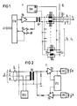
- Fig. 1 shows the main station H, a beacon control device.
- the main station H has a control device STH which is connected to a superordinate control computer LR.
- the control device STH is followed by a transmitting device SH and a receiving device EH.
- the output of the transmitting device SH of the main station leads to a transmitter ÜH.
- the two wires A and B of the transmission line ÜL are connected to the transformer UH via two matching resistors RA1 and RB1, each leading to a substation U1 to Un.
- Throttles DR1 are connected in parallel with the matching resistors RA and RB.
- the inductive resistance of these chokes DR1 which are each provided for a transmission line to the respective substation, is large compared to the matching resistances RA, RB lying parallel to it.
- a power supply device SVH is arranged in the main station, which leads to the respective C-wire of the transmission line with the zero potential.
- the live output of the power supply device SVH, labeled + U is connected to the center tap of the secondary winding of the transformer UH.
- the receiving device EH of the main station is connected to the primary winding of the transmitter UH.
- the output of the receiving device EH leads to the control device STH. This controls the receiving device EH of the main station via a control line.
- a throttle pair DR1 to DRn is provided for each transmission line ÜL1 to ÜLn.
- the matching resistors RA1 to RAn and RB to RBn are parallel to this.
- the information data coming from the master computer are transmitted in the main station H via the control device STH via the transmission device SH to the individual substations U1 to Un.
- the information sent by the substations U1 to Un is transmitted to the master computer LR via the receiving device EH of the main station and the control device STH of the main station.
- simultaneous transmission i.e. constant sending and receiving in the individual transmission gaps
- alternating sending and receiving i.e.
- the control device STH of the main station controls the transmitting and receiving device of the main station (SH and EH).
- the data received by the main station H via the transmission line ÜL are processed and sent to the actual beacon transmitter or data received by the beacon transmitter are transmitted to the main station.
- the substation U1 is shown in the block diagram in FIG.
- the data arrive from the main station H via the transmission line ÜL, which here has three wires A, B, C, to the substation U.
- the wires A and B lead to the primary winding of the transmitter ÜU of the substation.
- the wire C leads to the power supply device SVU of the substation, and a line also leads from the center tap of the primary winding of the transformer ÜU to the power supply device SVU of the substation.
- the transformer Un From the transformer Un, the data from the main station H to the receiving device EU of the sub station U and from there on the one hand to the control device STU of the sub station and on the other hand to the transmitting unit of the beacon transmitter via the secondary winding.
- the beacon transmitter is an infrared transmitter IRS shown, which sends the information data to the portable motor vehicles via infrared light IR. From there, the beacon receiver also receives the received data via the infrared radiation IR and the infrared receiving device IRE, which arrive in the substation U1 at the transmitting device SU of the substation and from there via the transmitter ÜU and the transmission line UL to the main station H. Both the receiving device EU and the transmitting device SU of the substation U are controlled by the control device STU, as described above and will be explained in more detail using further exemplary embodiments.
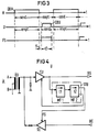
- FIG. 3 which represents a time diagram for an alternating dialog traffic, explains the transmission method for the information data.
- the main station H sends out data blocks DBH, switches to reception after sending out a data block DBH, during which time the substation U in turn sends its data block DBH to the main station H. Then the sub station U is again ready to receive the data block DBH of the main station H.
- This is illustrated in the first two diagrams.
- a time diagram is correspondingly shown for the release signal FS, which controls the transmission device (SU) of the substation U in this transmission method, namely the alternate transmission and reception.
- the control device of the substation is designed accordingly, as illustrated in FIG.
- the sub-station U which is connected to the transmission line UL via the transformer UU.
- the received signals lead from the transmitter UU to the receiving device EU of the substation U and from there to the control device STU and at the same time to the infrared transmitter IRS.
- the received signals from the infrared receiving device IRE go to the transmitting device SU of the substation and from there to the transmitter UU and then to the transmission line ÜL.
- the transmission device SU is acted upon by the control device STU with the release signal FS.
- the transmission information of the main station is divided into individual data blocks DBH.
- the main station is switched to receive between these transmitted data blocks, so that the substations can send their feedback DBU in these gaps.
- the data blocks are transmitted in the form of HDLC (High Level Data Link Control) protocols, whereby the operating mode NRZI (Never Retum to Zero Invert) is provided.
- An essential characteristic here is that the content of the data blocks is made transparent by inserting or leaving out zero bits, and that a signal change takes place after no more than six transmission clocks.
- the end of a data block DB can therefore only be recognized after seven transmit clocks at the earliest.
- the control device STU of the substation U is designed accordingly for this transmission method. It therefore has a first delay element, for example a retriggerable monoflop MF1 with a delay time of t1, which is continuously retriggered while the main station (H) is transmitting. Since the end of a data block DB can be recognized at the earliest after seven transmission clocks, the delay time t1 of the monoflop MF1 is selected to be equal to or greater than seven transmission clocks.
- the output of the monoflop MF1 triggers a second delay element, the monoflop MF2, with a delay time of t2.
- the receiving device EU of the substation U is blocked and the transmitting device SU of the substation U is released (release signal FS).
- release signal FS release signal FS
- a possible feedback from the substation U to the main station H can thus take place during the delay time t2 of the second monofiop MF2, as shown in the time diagram in FIG.
- the times t1 and t2 entered there correspond to the delay times of the first and second monoflops MF1 and MF2 in FIG.
- the first diagram shows the data blocks sent by the main station H, which are sent, for example, in a pulse-pause ratio of 1: 3.
- the main station H constantly sends to the sub-stations and the feedback from the sub-stations U to the main station takes place during the pulse pauses.
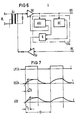
- the signal detection for the detection of a block end BE is shown under the time diagram of the transmission signals of the main station H and the transmission signals of the substation U. Below this, a time diagram is shown, which shows a section of the transmission signals of the main station and the substation.
- each sub-station In order to be able to transmit transmission signals from the sub-station of the main station in the pulse pauses of the constantly transmitting main station, each sub-station must derive its transmission signals from the received transmission signals of the main station with a corresponding control device, as is shown in FIG. 6 as an example.
- the substation transmits with a time delay or phase shift between the transmission pulses from the main station, as can be seen from the time diagrams in FIG. 5, lower half.
- the time diagram labeled ASU shows the signals that the astable flip-flop in the substation U (FIG. 6) derives from the transmission signals of the main station H for controlling the transmission device of the substation.
- TH is the time range of possible transmission pulses from the main station.
- tU is the time range of possible transmission pulses from the substation.
- the transmission signal from the main station consists of pulses, preferably with a pulse-pause ratio of 1: 3.
- the transmission signal of the substations is synchronized by the transmission signal of the main station and is delayed or out of phase between two possible transmission pulses of the main station.
- the transmission information of the main station can also be divided into individual data blocks, which, however, can also be strung together without gaps.
- the control unit of the main station changes continuously between the Sen operating mode and receive, the transmission device of the main station always remains switched on, but the receiver of the main station is switched to operational only in the range of possible transmission pulses from the substation.
- the control device is designed accordingly for this information transmission method, as shown in FIG.
- FIG. 6 shows a control device STU of the substation U possible for this method in the block diagram.
- the substation U is connected to the transmission line ÜL via the transformer ÜU of the substation.
- the receiving device EU of the substation Via the receiving device EU of the substation, the received data on the one hand reach an astable flip-flop ASU and a block end detection device BE and on the other hand to the infrared transmitter IRS.
- the data received by the infrared receiver IRE reach the transmitting device SU of the substation and from there via the transmitter UU and the transmission line ÜL to the main station.
- the control device STU of the substation U controls the receiving and transmitting device EU and SU of the substation U in accordance with the transmission methods explained above.
- the individual transmission pulses from the main station synchronize the astable multivibrator ASU.
- the block end detection device BE releases the transmission device SU of the substation via the AND gate, which is also acted upon by the astable multivibrator ASU.
- the receiving device EU of the substation is blocked.
- the receiving device EU of the substation is then released again, while the receiving device SU of the substation is blocked while receiving the information data from the main station.
- LPSH shows the logic level of the transmission signal in front of the transmission device SH of the main station.
- the shortest bit sequence time is designated tB.
- tB In order to avoid overcoupling between the individual wires of the transmission line, the rising and falling edges are ground.
- the rise and fall times of the transmission signal have a time constant S. This is shown in the second diagram, which is designated SSÜH and shows the transmission signals at the transmitter ÜH of the main station.
- the time constant t E of the receive signals of the substation is obtained in connection with the line capacity of the transmission line, which may fluctuate greatly over a longer period of time, where ⁇ - E max - 0.6. tB guarantees interference-free reception in the substation.
- the reception signals of the substation are also shown in the diagram and designated ESU as they occur at the entrance of the reception device EU of the substation.
Landscapes
- Engineering & Computer Science (AREA)
- Signal Processing (AREA)
- Computer Networks & Wireless Communication (AREA)
- Life Sciences & Earth Sciences (AREA)
- Atmospheric Sciences (AREA)
- Physics & Mathematics (AREA)
- General Physics & Mathematics (AREA)
- Selective Calling Equipment (AREA)
- Traffic Control Systems (AREA)
- Circuits Of Receivers In General (AREA)
Abstract
Description
Die Erfindung bezieht sich auf eine Anordnung für ein Verkehrsleit- und Informationssystem zur drahtgebundenen bidirektionalen Informationsübertragung in Form von Datenblöcken zwischen einer Hauptstation, die von einem Bakensteuergerät gebildet ist, und mehreren Unterstationen mit jeweils einem Bakensender und -empfänger, welche die Informationen mittels elektromagnetischer Wellen an ortsveränderliche Empfänger-/Sendereinheiten von Fahrzeuggeräten senden und von diesen empfangen, wobei der Dialogverkehr zwischen der Hauptstation und den Unterstationen entweder abwechselnd nacheinander oder gleichzeitig erfolgt.The invention relates to an arrangement for a traffic control and information system for wired bidirectional information transmission in the form of data blocks between a main station, which is formed by a beacon control device, and several substations, each with a beacon transmitter and receiver, which transmit the information by means of electromagnetic waves Send and receive portable receiver / transmitter units from vehicle devices, the dialog traffic between the main station and the substations either taking place in succession or simultaneously.
Ein Verkehrsleit- und Informationssystem für den individuellen Straßenverkehr ist beispielsweise aus den deutschen Offenlegungsschriften 29 23 634 und 29 36 062 bekannt. Ein derartiges Verkehrsleit- und Informationssystem (z.B. "AUTO-SCOUT") erfordert eine entsprechende Infrastruktur, die mit möglichst geringem Aufwand geschaffen werden soll. So können beispielsweise vorhandene Verkehrsrechner für eine verkehrsabhängige Lichtsignalanlagensteuerung mit herangezogen werden. Die Sender und Empfänger der Baken können unmittelbar an den Lichtsignalgebern montiert sein. Für ein obengenanntes Verkehrsleitsystem müssen zwischen der oder den ortsfesten Baken und den ortsveränderlichen Fahrzeuggeräten der Kraftfahrzeuge in relativ kurzer Zeit große Datenmengen für den Informationsaustausch zuverlässig übertragen werden. Ein Verfahren und eine Einrichtung hierfür ist beispielsweise in der DE-OS 3 304 451 beschrieben. Für die Informationsübertragung mit hohen Datenraten sind eigene Übertragungsleitungen zwischen einem Bakensteuergerät, das mit einem übergeordneten Leitrechner verbunden ist, und den einzelnen Bakensendern und -empfängern, z.B. an einer Straßenkreuzung erforderlich. Hierfür ist die Verlegung von geschirmten Spezialkabeln notwendig. Dies ist jedoch aufwendig und sehr kostenintensiv, insbesondere im Kreuzungsbereich. Um eine Neuverlegung von Kabeln zu vermeiden, sollen bereits verlegte, im allgemeinen ungeschirmte Erdkabel für das Verkehrsleitsystem mit benützt werden können. Dabei stehen im allgemeinen nur wenig freie Adern eines Erdkabels zur Verfügung, das beispielsweise zwischen einem Signalanlagen-Steuergerät und den einzelnen Lichtsignalgebem verlegt ist.A traffic control and information system for individual road traffic is known, for example, from German Offenlegungsschriften 29 23 634 and 29 36 062. Such a traffic control and information system (e.g. "AUTO-SCOUT") requires an appropriate infrastructure that should be created with as little effort as possible. For example, existing traffic computers can also be used for traffic-dependent traffic light system control. The transmitters and receivers of the beacons can be mounted directly on the light signal transmitters. For an above-mentioned traffic control system, large amounts of data for the exchange of information must be reliably transmitted between the fixed beacon (s) and the portable vehicle devices of the motor vehicles. A method and a device for this is described for example in DE-OS 3 304 451. For the transmission of information with high data rates, separate transmission lines between a beacon control device, which is connected to a higher-level master computer, and the individual beacon transmitters and receivers, e.g. required at an intersection. This requires the laying of shielded special cables. However, this is complex and very expensive, especially in the intersection area. In order to avoid re-laying cables, it should be possible to use already laid, generally unshielded underground cables for the traffic control system. There are generally only a few free wires of an underground cable available, which is laid, for example, between a signaling system control unit and the individual light signal transmitters.
Der Erfindung liegt daher die Aufgabe zugrunde, für ein eingangs genanntes Verkehrsleit- und Informationssystem eine Anordnung anzugeben, die es gestattet, über bereits installierte Leitungen mit einer möglichst geringen Anzahl von Leitungsadem Informationsdaten zwischen einem Bakensteuergerät und mehreren Bakensendem und -empfängern zu übertragen.The invention is therefore based on the object of specifying an arrangement for a traffic control and information system mentioned at the outset which allows information data to be transmitted between a beacon control device and a plurality of beacon transmitters and receivers over already installed lines with the smallest possible number of line baffles.
Diese Aufgabe wird erfindungsgemäß dadurch gelöst, daß in der Hauptstation eine Sende- und eine Empfangseinrichtung, die an einem an eine Obertragungsleitung angeschalteten Übertrager angeschlossen sind, eine Steuereinrichtung, die einerseits mit der Sende- und Empfangseinrichtung und andererseits mit einem Leitrechner verbunden ist, und eine Stromfernversorgungseinrichtung für die Unterstationen vorgesehen sind, daß die Hauptstation mit mehreren Unterstationen über jeweils eine Übertragungsleitung mit einer geringen Anzahl von Leitungsadem verbunden ist, die sowohl der Informationsübertragung als auch der Stromfernversorgung dienen, daß jede Unterstation eine Stromversorgungseinrichtung und einen Übertrager aufweist, die an der Übertragungsleitung angeschlossen sind, daß dem Übertrager der Unterstation eine Empfangseinrichtung nachgeschaltet ist, deren Ausgang mit einer Steuereinrichtung der Unterstation und dem Bakensender verbunden ist, und daß die Unterstation einen von den Bakenempfänger beaufschlagte Sendeeinrichtung aufweist, die mit dem Übertrager verbunden ist, wobei die Steuereinrichtung der Unterstation die Empfangs- und die Sendeeinrichtung in Abhängigkeit von den Sendesignalen der Hauptstation steuert.This object is achieved in that in the main station a transmitting and receiving device which are connected to a transmitter connected to a transmission line, a control device which is connected on the one hand to the transmitting and receiving device and on the other hand to a host computer, and a Remote power supply device is provided for the substations, that the main station is connected to a plurality of substations via a transmission line each with a small number of line core, which serve both the transmission of information and the remote power supply, that each substation has a power supply device and a transmitter connected to the transmission line are connected that the transmitter of the substation is followed by a receiving device whose output is connected to a control device of the substation and the beacon transmitter, and that the substation one has transmitting device acted upon by the beacon receiver, which is connected to the transmitter, the control device of the substation controlling the receiving and transmitting devices as a function of the transmission signals of the main station.
Aus der FR-A 2 436 537 ist es bekannt, daß die Unterstation die Empfangs- und die Sendeeinrichtung in Abhängigkeit von den Sendesignalen der Hauptstation steuert.From FR-
Für den Dialogverkehr zwischen der Hauptstation und mehreren Unterstationen weist das Übertragungssystem erfindungsgemäß in der Hauptstation (Bakensteuergerät) sowohl eine Sende- als auch eine Empfangseinrichtung auf, die beide über eine Übertragungsleitung mit jeweils einer Unterstation verbunden sind. Diese weist ebenfalls eine Empfangs- und eine Sendeeinrichtung auf, die über einen Übertrager an der Übertragungsleitung angeschlossen sind und die ihrerseits auf den Bakensender bzw. -empfänger führen. Sowohl in der Hauptstation als auch in der jeweiligen Unterstation ist jeweils ein Steuergerät vorgesehen, um den Dialogverkehr je nach der Übertragungsart, nämlich abwechselnd nacheinander oder gleichzeitig, zu steuern. Dabei ist das Steuergerät der Unterstation so ausgestaltet, daß es in Abhängigkeit von den empfangenen Sendesignalen der Sendeeinrichtung der Hauptstation die Empfangs- und Sendeeinrichtung der Unterstation steuert.For the dialog traffic between the main station and several substations, the transmission system according to the invention has both a transmitting and a receiving device in the main station (beacon control device), both of which are connected to a respective substation via a transmission line. This has also a reception - and transmission means, which are connected via a transformer to the transmission line and which in turn lead to the beacon transmitter or receiver. A control device is provided both in the main station and in the respective substation in order to control the dialog traffic depending on the type of transmission, namely alternately in succession or simultaneously. The control unit of the substation is designed so that it controls the receiving and transmitting device of the substation as a function of the received transmission signals from the transmission device of the main station.
Zweckmäßigerweise weist die Übertragungsleitung nur drei Leitungsadern auf, die sowohl für den Informationsaustausch als auch für die Stromfern- übertragung von der Hauptstation zu den Unterstationen genutzt wird. Dabei kann die eine der drei Adern, an der das Nullpotential der Stromversorgungseinrichtung liegt, auf Erdpotential liegen, so daß im Grunde genommen lediglich zwei freie Adern für den Informationsaustausch für das Verkehrsleit- und Informationssystem ausreichend sind.The transmission line expediently has only three line wires which are used both for the exchange of information and for the long-distance transmission of electricity from the main station to the substations. The one of the three wires on which the zero potential of the power supply device is located can be at earth potential, so that basically only two free wires are sufficient for the exchange of information for the traffic control and information system.
Bei einem abwechselnden Dialogverkehr, d.h. das Bakensteuergerät (Hauptstation) sendet die Informationsdaten und schaltet dann auf Empfang, während dieser Zeit werden die von den Unterstationen gesendeten Daten in der Hauptstation empfangen, werden die Informationsdaten in Datenblöcken in HDLC-Protokollen (High Level Data Link Control) übertragen. Bei der Übertragung der Datenblöcke in Form von HDLC-Protokollen wird die Betriebsart NRZI (Never Retum to Zero Invert) verwendet. Für diese Ubertragungsart ist es kennzeichnend, daß nach spätestens sechs Sendetakten ein Signalwechsel erfolgt. Das Ende eines Datenblocks kann somit frühestens nach sieben Sendetakten erkannt werden.When there is an alternating dialog traffic, i.e. the beacon control unit (main station) sends the information data and then switches to reception, during this time the data sent by the substations is received in the main station, the information data is stored in data blocks in HDLC protocols (High Level Data Link Control ) transfer. When transmitting the data blocks in the form of HDLC protocols, the operating mode NRZI (Never Retum to Zero Invert) is used. It is known for this type of transmission drawing that a signal change occurs after no more than six transmission clocks. The end of a data block can therefore only be recognized after seven transmission clocks at the earliest.
In einer zweckmäßigen Ausgestaltung der Erfindung ist daher in jeder Unterstation die Steuereinrichtung mit einem retriggerbaren Verzögerungsglied mit einer bestimmten Verzögerungszeit vorgesehen, die gleich oder größer ist als die Zeit von sieben Sendetakten. Dem ersten Verzögerungsglied ist ein zweites Verzögerungsglied nachgeschaltet, das entsprechend seiner Verzögerungszeit die Empfangseinrichtung der Unterstation sperrt und die Sendeeinrichtung der Unterstation freigibt. Auf diese Weise ist eine wechselseitige Umschaltung von Senden auf Empfangen sichergestellt.In an expedient embodiment of the invention, the control device is therefore provided in each substation with a retriggerable delay element with a specific delay time which is equal to or greater than the time of seven transmission clocks. The first delay element is followed by a second delay element, which blocks the receiving device of the substation in accordance with its delay time and releases the transmitting device of the substation. This ensures a reciprocal changeover from sending to receiving.
In einer weiteren Ausgestaltung der erfindungsgemäßen Anordnung für den Dialogverkehr, der gleichzeitig stattfindet, ist die Steuereinrichtung der Unterstation entsprechend ausgebildet. Die Hauptstation sendet dabei mit einem vorgegebenen Impulsraster ständig, zwischen den einzelnen Sendeimpulsen ist sie auf Empfang geschaltet, während dieser Zeit sendet die Unterstation. Dazu weist zweckmäßigerweise jede Unterstation in der Steuereinrichtung eine astabile Kippstufe und eine Datenblockende-Erkennungseinrichtung auf, die über ein logisches Verknüpfungsglied die Sendeeinrichtung der Unterstation steuern. Auf diese Weise wird in der Unterstation von den empfangenen Sendesignalen der Hauptstation das Sendesignal für die Unterstation abgeleitet, wobei die Unterstation zeitverzögert bzw. phasenverschoben zwischen den Sendeimpulsen der Hauptstation sendet.In a further embodiment of the arrangement according to the invention for dialog traffic that takes place simultaneously, the control device of the substation is designed accordingly. The main station continuously transmits with a predetermined pulse pattern, it is switched to receive between the individual transmit pulses, during which the sub-station transmits. For this purpose, each substation in the control device expediently has an astable flip-flop and a data block end detection device which control the transmission device of the substation via a logic link. In this way, the transmission signal for the substation is derived in the substation from the received transmission signals of the main station, the substation transmitting with a time delay or out of phase between the transmission pulses of the main station.
Anhand der Zeichnung wird die erfindungsgemä-Be Anordnung im einzelnen erläutert.The arrangement according to the invention is explained in detail with reference to the drawing.
Dabei zeigen
- Fig. 1 eine mögliche Anordnung der Hauptstation im Blockschaltbild,
- Fig. 2 eine mögliche Anordnung der Unterstation in Blockschaltbild,
- Fig. 3 ein Zeitdiagramm für abwechselnden Dialogverkehr,
- Fig. 4 ein Schaltbeispiel für die Steuereinrichtung der Unterstation,
- Fig. 5 ein Zeitdiagramm für gleichzeitigen Dialogverkehr,
- Fig. 6 ein Schaltbeispiel der Steuereinrichtung der Unterstation und
- Fig. 7 Pegeldiagramme der Sende- bzw. Empfangssignale.
- 1 shows a possible arrangement of the main station in the block diagram,
- 2 shows a possible arrangement of the substation in a block diagram,
- 3 shows a time diagram for alternating dialogue traffic,
- 4 shows a circuit example for the control device of the substation,
- 5 shows a time diagram for simultaneous dialog traffic,
- Fig. 6 is a circuit example of the control device of the substation and
- Fig. 7 level diagrams of the transmit or receive signals.
In Fig. 1 und 2 ist die erfindungsgemäße Anordnung im Blockschaltbild dargestellt. Fig. 1 zeigt die Hauptstation H, ein Bakensteuergerät. Die Hauptstation H weist eine Steuereinrichtung STH auf, die mit einem übergeordneten Leitrechner LR verbunden ist. Der Steuereinrichtung STH ist eine Sendeeinrichtung SH und eine Empfangseinrichtung EH nachgeordnet. Der Ausgang der Sendeeinrichtung SH der Hauptstation führt zu einem Übertrager ÜH. Sekundärseitig sind am Übertrager ÜH über zwei Anpassungswiderstände RA1 und RB1 die beiden Adern A und B der Übertragungsleitung ÜL verbunden, die jeweils zu einer Unterstation U1 bis Un führen. Zu den Anpassungswiderständen RA und RB parallel sind jeweils Drosseln DR1 geschaltet. Für die Datenübertragung ÜL1 ist der induktive Widerstand dieser Drosseln DR1, die jeweils für eine Übertragungsleitung zur jeweiligen Unterstation vorgesehen sind, groß gegenüber den dazu parallel liegenden Anpassungswiderständen RA, RB. Für die Femstromversorgung der Unterstationen U1 bis Un ist eine Stromversorgungseinrichtung SVH in der Hauptstation angeordnet, die mit dem Nullpotential zur jeweiligen C-Ader der Übertragungsleitung führt. Der spannungsführende Ausgang der Stromversorgungseinrichtung SVH, mit +U bezeichnet, ist an die Mittelanzapfung der Sekundärwicklung des Übertragers ÜH geführt. Die Empfangseinrichtung EH der Hauptstation ist an der Primärwicklung des Übertragers UH angeschlossen. Der Ausgang der Empfangseinrichtung EH führt zur Steuereinrichtung STH. Diese steuert über eine Steuerleitung die Empfangseinrichtung EH der Hauptstation. Für jede Übertragungsleitung ÜL1 bis ÜLn ist ein Drosselpaar DR1 bis DRn vorgesehen. Dazu parallel liegen die Anpassungswiderstände RA1 bis RAn und RB bis RBn. Die vom Leitrechner kommenden Informationsdaten werden in der Hauptstation H über die Steuereinrichtung STH über die Sendeeinrichtung SH an die einzelnen Unterstationen U1 bis Un übertragen. Die von den Unterstationen U1 bis Un gesendeten Informationen werden über die Empfangseinrichtung EH der Hauptstation und der Steuereinrichtung STH der Hauptstation an den Leitrechner LR übertragen. Je nach gewähltem Übertragungsverfahren für den Informationsaustausch, entweder gleichzeitige Übertragung, also ständiges Senden und Empfangen in den einzelnen Sendelücken oder abwechselndes Senden und Empfangen, d.h. Umschalten von Senden auf Empfangen, werden von der Steuereinrichtung STH der Hauptstation die Sende- und Empfangseinrichtung der Hauptstation (SH und EH) gesteuert. In der Unterstation U gemäß Fig.2 (Blockschaltbild) werden die von der Hauptstation H über die Übertragungsleitung ÜL empfangenen Daten verarbeitet und an den eigentlichen Bakensender gegeben oder vom Bakensender empfangenen Daten zur Hauptstation übertragen.1 and 2, the arrangement according to the invention is shown in the block diagram. Fig. 1 shows the main station H, a beacon control device. The main station H has a control device STH which is connected to a superordinate control computer LR. The control device STH is followed by a transmitting device SH and a receiving device EH. The output of the transmitting device SH of the main station leads to a transmitter ÜH. On the secondary side, the two wires A and B of the transmission line ÜL are connected to the transformer UH via two matching resistors RA1 and RB1, each leading to a substation U1 to Un. Throttles DR1 are connected in parallel with the matching resistors RA and RB. For the data transmission ÜL1, the inductive resistance of these chokes DR1, which are each provided for a transmission line to the respective substation, is large compared to the matching resistances RA, RB lying parallel to it. For the remote power supply of the substations U1 to Un, a power supply device SVH is arranged in the main station, which leads to the respective C-wire of the transmission line with the zero potential. The live output of the power supply device SVH, labeled + U, is connected to the center tap of the secondary winding of the transformer UH. The receiving device EH of the main station is connected to the primary winding of the transmitter UH. The output of the receiving device EH leads to the control device STH. This controls the receiving device EH of the main station via a control line. A throttle pair DR1 to DRn is provided for each transmission line ÜL1 to ÜLn. The matching resistors RA1 to RAn and RB to RBn are parallel to this. The information data coming from the master computer are transmitted in the main station H via the control device STH via the transmission device SH to the individual substations U1 to Un. The information sent by the substations U1 to Un is transmitted to the master computer LR via the receiving device EH of the main station and the control device STH of the main station. Depending on the transmission method selected for the exchange of information, either simultaneous transmission, i.e. constant sending and receiving in the individual transmission gaps, or alternating sending and receiving, i.e. Switching from sending to receiving, the control device STH of the main station controls the transmitting and receiving device of the main station (SH and EH). In the substation U according to FIG. 2 (block diagram), the data received by the main station H via the transmission line ÜL are processed and sent to the actual beacon transmitter or data received by the beacon transmitter are transmitted to the main station.
In Fig. 2 ist die Unterstation U1 im Blockschaltbild gezeigt. Von der Hauptstation H gelangen die Daten über die Übertragungsleitung ÜL, die hier drei Adern A,B,C aufweist, an die Unterstation U. Dabei führen die Adern A und B auf die Primärwicklung des Übertragers ÜU der Unterstation. Die Ader C führt zur Stromversorgungseinrichtung SVU der Unterstation, ebenso führt von der Mittelanzapfung der Primärwicklung des Übertragers ÜU eine Leitung zur Stromversorgungseinrichtung SVU der Unterstation. Vom Übertrager Un gelangen über die Sekundärwicklung die Daten von der Hauptstation H zur Empfangseinrichtung EU der Unterstation U und von da einerseits an die Steuereinrichtung STU der Unterstation und andererseits an die Sendeeinheit des Bakensenders. In diesem Beispiel ist der Bakensender als Infrarotsender IRS dargestellt, der über Infrarotlicht IR die Informationsdaten an die ortsveränderlichen Kraftfahrzeuge sendet. Von dort aus erhält auch der Bakenempfänger über die Infrarotstrahlung IR und der Infrarotempfangseinrichtung IRE die Empfangsdaten, die in der Unterstation U1 an die Sendeeinrichtung SU der Unterstation gelangen und von dort über den Übertrager ÜU und der Übertragungsleitung UL an die Hauptstation H gelangen. Dabei wird von der Steuereinrichtung STU sowohl die Empfangseinrichtung EU als auch die Sendeeinrichtung SU der Unterstation U gesteuert, wie oben beschrieben und an weiteren Ausführungsbeispielen noch näher erläutert wird.The substation U1 is shown in the block diagram in FIG. The data arrive from the main station H via the transmission line ÜL, which here has three wires A, B, C, to the substation U. The wires A and B lead to the primary winding of the transmitter ÜU of the substation. The wire C leads to the power supply device SVU of the substation, and a line also leads from the center tap of the primary winding of the transformer ÜU to the power supply device SVU of the substation. From the transformer Un, the data from the main station H to the receiving device EU of the sub station U and from there on the one hand to the control device STU of the sub station and on the other hand to the transmitting unit of the beacon transmitter via the secondary winding. In this example the beacon transmitter is an infrared transmitter IRS shown, which sends the information data to the portable motor vehicles via infrared light IR. From there, the beacon receiver also receives the received data via the infrared radiation IR and the infrared receiving device IRE, which arrive in the substation U1 at the transmitting device SU of the substation and from there via the transmitter ÜU and the transmission line UL to the main station H. Both the receiving device EU and the transmitting device SU of the substation U are controlled by the control device STU, as described above and will be explained in more detail using further exemplary embodiments.
Zunächst ist an der Figur 3, die ein Zeitdiagramm für einen abwechselnden Dialogverkehr darstellt, das Ubertragungsverfahren für die Informationsdaten erläutert. Die Hauptstation H sendet Datenblöcke DBH aus, schaltet nach Aussenden eines Datenblocks DBH auf Empfang, während dieser Zeit sendet die Unterstation U ihrerseits ihren Datenblock DBH an die Hauptstation H. Danach ist die Unterstation U wieder empfangsbereit für den Datenblock DBH der Hauptstation H. Dies ist in den beiden ersten Diagrammen veranschaulicht. Darunter ist ein Zeitdiagramm entsprechend dargestellt für das Freigabesignal FS, das die Sendeeinrichtung (SU) der Unterstation U bei diesem Übertragungsverfahren, nämlich das abwechselnde Senden und Empfangen steuert. Dafür ist die Steuereinrichtung der Unterstation entsprechend ausgebildet, wie dies in Fig.4 veranschaulicht ist.First of all, FIG. 3, which represents a time diagram for an alternating dialog traffic, explains the transmission method for the information data. The main station H sends out data blocks DBH, switches to reception after sending out a data block DBH, during which time the substation U in turn sends its data block DBH to the main station H. Then the sub station U is again ready to receive the data block DBH of the main station H. This is illustrated in the first two diagrams. Below this, a time diagram is correspondingly shown for the release signal FS, which controls the transmission device (SU) of the substation U in this transmission method, namely the alternate transmission and reception. The control device of the substation is designed accordingly, as illustrated in FIG.
In Fig.4 ist im Blockschaltbild die Unterstation U dargestellt, die über den Übertrager UU an der Übertragungsleitung UL angeschlossen ist. Vom Übertrager UU führen die Empfangssignale zur Empfangseinrichtung EU der Unterstation U und von da zur Steuereinrichtung STU und gleichzeitig zum Infrarotsender IRS. Die empfangenen Signale von der Infrarotempfangseinrichtung IRE gelangen zu der Sendeeinrichiung SU der Unterstation und von da zum Übertrager UU und dann auf die Ubertragungsleitung ÜL. Die Sendeeinrichtung SU wird von der Steuereinrichtung STU mit dem Freigabesignal FS beaufschlagt. Wie anhand der Fig. 3 schon erwähnt, werden die Sendeinformationen der Hauptstation in einzelne Datenblöcke DBH gegliedert. Zwischen diesen gesendeten Datenblöcke ist die Hauptstation auf Empfang geschaltet, so daß in diesen Lücken die Unterstationen ihre Rückmeldungen DBU senden können. Die Übertragung der Datenblöcke erfolgt dabei in Form von HDLC (High Level Data Link Control)-Protokollen, wobei die Betriebsart NRZI (Never Retum to Zero Invert) vorgesehen ist. Ein wesentliches Kennzeichen ist dabei, daß der Inhalt der Datenblöcke durch Einfügen oder Weglassen von Null-Bits codetransparent gemacht wird, und daß nach spätestens sechs Sendetakten ein Signalwechsel erfolgt. Das Ende eines Datenblocks DB kann somit frühestens nach sieben Sendetakten erkannt werden. Für dieses Übertragungsverfahren ist die Steuereinrichtung STU der Unterstation U entsprechend ausgebildet. Sie weist daher ein erstes Verzögerungsglied, beispielsweise ein retriggerbares Monoflop MF1 mit einer Verzögerungszeit von t1 auf, das während die Hauptstation (H) sendet fortlaufend nachgetriggert wird. Da das Ende eines Datenblocks DB frühestens nach sieben Sendetakten erkannt werden kann, wird die Verzögerungszeit t1 des Monoflops MF1 gleich oder größer als sieben Sendetakte gewählt.4 shows the sub-station U, which is connected to the transmission line UL via the transformer UU. The received signals lead from the transmitter UU to the receiving device EU of the substation U and from there to the control device STU and at the same time to the infrared transmitter IRS. The received signals from the infrared receiving device IRE go to the transmitting device SU of the substation and from there to the transmitter UU and then to the transmission line ÜL. The transmission device SU is acted upon by the control device STU with the release signal FS. As already mentioned with reference to FIG. 3, the transmission information of the main station is divided into individual data blocks DBH. The main station is switched to receive between these transmitted data blocks, so that the substations can send their feedback DBU in these gaps. The data blocks are transmitted in the form of HDLC (High Level Data Link Control) protocols, whereby the operating mode NRZI (Never Retum to Zero Invert) is provided. An essential characteristic here is that the content of the data blocks is made transparent by inserting or leaving out zero bits, and that a signal change takes place after no more than six transmission clocks. The end of a data block DB can therefore only be recognized after seven transmit clocks at the earliest. The control device STU of the substation U is designed accordingly for this transmission method. It therefore has a first delay element, for example a retriggerable monoflop MF1 with a delay time of t1, which is continuously retriggered while the main station (H) is transmitting. Since the end of a data block DB can be recognized at the earliest after seven transmission clocks, the delay time t1 of the monoflop MF1 is selected to be equal to or greater than seven transmission clocks.
Der Ausgang des Monoflops MF1 triggert ein zweites Verzögerungsglied, das Monoflop MF2, mit einer Verzögerungszeit von t2. Während dieser Verzögerungszeit t2 des zweiten Monoflops MF2 wird die Empfangseinrichtung EU der Unterstation U gesperrt und die Sendeeinrichtung SU der Unterstation U freigegeben (Freigebesignal FS). Eine mögliche Rückmeldung von der Unterstation U zur Hauptstation H kann somit während der Verzögerungszeit t2 des zweiten Monofiops MF2 erfolgen, wie dies im Zeitdiagramm der Fig.3 dargestellt ist. Die dort eingetragenen Zeiten t1 und t2 entsprechen den Verzögerungszeiten des ersten und des zweiten Monoflops MF1 und MF2 der Fig.4.The output of the monoflop MF1 triggers a second delay element, the monoflop MF2, with a delay time of t2. During this delay time t2 of the second monoflop MF2, the receiving device EU of the substation U is blocked and the transmitting device SU of the substation U is released (release signal FS). A possible feedback from the substation U to the main station H can thus take place during the delay time t2 of the second monofiop MF2, as shown in the time diagram in FIG. The times t1 and t2 entered there correspond to the delay times of the first and second monoflops MF1 and MF2 in FIG.
In Fig.5 sind Zeitdiagramm für die gleichzeitige Informationsübertragung dargestellt. Das erste Diagramm zeigt die von der Hauptstation H gesendeten Datenblöcke, die beispielsweise in einem Impuls- Pausen-Verhältnis von 1 : 3 gesendet werden. Bei diesem Übertragungsverfahren sendet die Hauptstation H zu den Unterstationen ständig und die Rückmeldung von den Unterstationen U zur Hauptstation erfolgt in den Impulspausen. Unter dem Zeitdiagramm der Sendesignale der Hauptstation H und der Sendesignale der Unterstation U ist die Signalerkennung für das Erkennen eines Blocksende BE dargestellt. Darunter ist ein Zeitdiagramm gezeigt, das einen Ausschnitt aus den Sendesignalen der Hauptstation und der Unterstation zeigt. Um in den Impulspausen der ständig sendenden Hauptstation Sendesignale von der Unterstation der Hauptstation übertragen zu können, muß jede Unterstation aus den empfangenen Sendesignalen der Hauptstation seine Sendesignale mit einer entsprechenden Steuereinrichtung, wie sie in Fig.6 beispielhaft gezeigt ist, ableiten. Dabei sendet die Unterstation zeitverzögert bzw. phasenverschoben zwischen den Sendeimpulsen der Hauptstation, wie dies aus den Zeitdiagrammen der Fig. 5, untere Hälfte ersichtlich ist. Das mit ASU bezeichnete Zeitdiagramm zeigt die Signale, die die astabile Kippstufe in der Unterstation U (Fig.6) aus den Sendesignalen der Hauptstation H für die Steuerung der Sendeeinrichtung der Unterstation ableitet. Dabei ist tH der Zeitbereich möglicher Sendeimpulse der Hauptstation. tU ist der Zeitbereich möglicher Sendeimpulse der Unterstation. Hier ist also gezeigt, daß das Sendesignal der Hauptstation aus Impulsen vorzugsweise mit einem Impuls-Pausen-Verhältnis von 1 : 3 besteht. Das Sendesignal der Unterstationen wird vom Sendesignal der Hauptstation synchronisiert und liegt zeitverzögert bzw. phasenverschoben zwischen zwei möglichen Sendeimpulsen der Hauptstation. Dabei kann sich die Sendeinformation der Hauptstation ebenfalls in einzelne Datenblöcke gliedem, die sich jedoch auch lückenlos aneinanderreihen können. Die Steuereinrichtung der Hauptstation wechselt laufend zwischen der Betriebsart Senden und Empfangen, wobei die Sendeeinrichtung der Hauptstation immer eingeschaltet bleibt, der Empfänger der Hauptstation jedoch nur im Bereich möglicher Sendeimpulse seitens der Unterstation betriebsbereit geschaltet wird. Für dieses Informations-Übertragungsverfahren ist die Steuereinrichtung entsprechend ausgebildet, wie dies in Fig.6 dargestellt ist.5 shows a time diagram for the simultaneous transmission of information. The first diagram shows the data blocks sent by the main station H, which are sent, for example, in a pulse-pause ratio of 1: 3. In this transmission method, the main station H constantly sends to the sub-stations and the feedback from the sub-stations U to the main station takes place during the pulse pauses. The signal detection for the detection of a block end BE is shown under the time diagram of the transmission signals of the main station H and the transmission signals of the substation U. Below this, a time diagram is shown, which shows a section of the transmission signals of the main station and the substation. In order to be able to transmit transmission signals from the sub-station of the main station in the pulse pauses of the constantly transmitting main station, each sub-station must derive its transmission signals from the received transmission signals of the main station with a corresponding control device, as is shown in FIG. 6 as an example. The substation transmits with a time delay or phase shift between the transmission pulses from the main station, as can be seen from the time diagrams in FIG. 5, lower half. The time diagram labeled ASU shows the signals that the astable flip-flop in the substation U (FIG. 6) derives from the transmission signals of the main station H for controlling the transmission device of the substation. TH is the time range of possible transmission pulses from the main station. tU is the time range of possible transmission pulses from the substation. Here it is shown that the transmission signal from the main station consists of pulses, preferably with a pulse-pause ratio of 1: 3. The transmission signal of the substations is synchronized by the transmission signal of the main station and is delayed or out of phase between two possible transmission pulses of the main station. The transmission information of the main station can also be divided into individual data blocks, which, however, can also be strung together without gaps. The control unit of the main station changes continuously between the Sen operating mode and receive, the transmission device of the main station always remains switched on, but the receiver of the main station is switched to operational only in the range of possible transmission pulses from the substation. The control device is designed accordingly for this information transmission method, as shown in FIG.
In Fig.6 ist ein für dieses Verfahren mögliche Steuereinrichtung STU der Unterstation U im Blockschaltbild dargestellt. Über den Übertrager ÜU der Unterstation ist die Unterstation U an der Übertragungsleitung ÜL angeschlossen. Über die Empfangseinrichtung EU der Unterstation gelangen die Empfangsdaten einerseits an eine astabile Kippstufe ASU und eine Blockende-Erkennungseinrichtung BE und andererseits an den Infrarotsender IRS.FIG. 6 shows a control device STU of the substation U possible for this method in the block diagram. The substation U is connected to the transmission line ÜL via the transformer ÜU of the substation. Via the receiving device EU of the substation, the received data on the one hand reach an astable flip-flop ASU and a block end detection device BE and on the other hand to the infrared transmitter IRS.
Die vom Infrarotempfänger IRE empfangenen Daten gelangen an die Sendeeinrichtung SU der Unterstation und von da über den Übertrager UU und die Übertragungsleitung ÜL zur Hauptstation. Die Steuereinrichtung STU der Unterstation U steuert entsprechend den oben erläuterten Übertragungsverfahren die Empfangs- und Sendeeinrichtung EU und SU der Unterstation U. Die einzelnen Sendeimpulse der Hauptstation synchronisieren die astabile Kippstufe ASU. Die Blockende-Erkennungseinrichtung BE gibt über das UND-Glied, das gleichzeitig auch von der astabilen Kippstufe ASU beaufschlagt ist, die Sendeeinrichtung SU der Unterstation zum Senden frei. In dieser Zeit ist die Empfangseinrichtung EU der Unterstation gesperrt. Danach wird die Empfangseinrichtung EU der Unterstation wieder freigegeben, während des Empfangs der Informationsdaten von der Hauptstation ist die Sendeeinrichtung SU der Unterstation gesperrt ist.The data received by the infrared receiver IRE reach the transmitting device SU of the substation and from there via the transmitter UU and the transmission line ÜL to the main station. The control device STU of the substation U controls the receiving and transmitting device EU and SU of the substation U in accordance with the transmission methods explained above. The individual transmission pulses from the main station synchronize the astable multivibrator ASU. The block end detection device BE releases the transmission device SU of the substation via the AND gate, which is also acted upon by the astable multivibrator ASU. During this time, the receiving device EU of the substation is blocked. The receiving device EU of the substation is then released again, while the receiving device SU of the substation is blocked while receiving the information data from the main station.
In Fig. 7 sind die Signalformen der Sendeimpulse der Hauptstation und der Empfangssignale der Unterstation dargestellt. LPSH zeigt den Logikpegel des Sendesignals vor der Sendeeinrichtung SH der Hauptstation. Dabei ist die kürzestes Bitfolgezeit mit tB bezeichnet. Um ein Überkoppeln zwischen den einzelnen Adern der Übertragungsleitung zu vermeiden, werden die Anstiegs- und Abfallflanken verschliffen. Dabei weisen die Anstiegs- und Abfallzeiten des Sendesignals eine Zeitkonstante S auf. Dies ist im zweiten Diagramm gezeigt, das mit SSÜH bezeichnet ist und die Sendesignale am Übertrager ÜH der Hauptstation zeigt. Dabei entspricht die Zeitkonstante is = 0,1 . tB, wobei tB die kürzeste Bitfolgezeit ist. Die Zeitkonstante tE der Empfangssignale der Unterstation ergibt sich in Verbindung mit der über einen längeren Zeitraum gegebenenfalls stark schwankenden Leitungskapazität der Übertragungsleitung, wobei τ-E max - 0,6 . tB einen störungsfreien Empfang in der Unterstation gewährleistet. Die Empfangssignale der Unterstation sind ebenfalls im Diagramm dargestellt und mit ESU bezeichnet, wie sie am Eingang der Empfangseinrichtung EU der Unterstation auftreten.7 shows the waveforms of the transmission pulses of the main station and the reception signals of the sub station. LPSH shows the logic level of the transmission signal in front of the transmission device SH of the main station. The shortest bit sequence time is designated tB. In order to avoid overcoupling between the individual wires of the transmission line, the rising and falling edges are ground. The rise and fall times of the transmission signal have a time constant S. This is shown in the second diagram, which is designated SSÜH and shows the transmission signals at the transmitter ÜH of the main station. The time constant is = 0.1. tB, where tB is the shortest bit sequence time. The time constant t E of the receive signals of the substation is obtained in connection with the line capacity of the transmission line, which may fluctuate greatly over a longer period of time, where τ- E max - 0.6. tB guarantees interference-free reception in the substation. The reception signals of the substation are also shown in the diagram and designated ESU as they occur at the entrance of the reception device EU of the substation.
Entsprechendes gilt auch für die Zeitkonstanten der Sendesignale der Unterstation und der Empfangssignale der Hauptstation.The same applies to the time constants of the transmission signals of the substation and the reception signals of the main station.
- H HauptstationH main station
- U UnterstationU substation
- STH Steuereinrichtung der HSTH control device of the H
- STU Steuereinrichtung der USTU control device of the U
- SH Sendeeinrichtung der HSH transmitter of the H
- SU Sendeeinrichtung der USU transmitter of the U
- EH Empfangseinrichtung der HEH reception facility of the H
- EU Empfangseinrichtung der UEU reception facility of the U
- ÜH Übertrager der HÜH transmitter of the H
- ÜU Übertrager der UÜU transmitter of the U
- RA, RB Anpassungs-WiderständeRA, RB matching resistors
- A,B,C Adern der ULA, B, C UL wires
- ÜL ÜbertragungsleitungÜL transmission line
- U1,U2,... Un UnterstationenU1, U2, ... Un substations
- DR DrosselDR throttle
- SVH Stromversorgungseinrichtung der HSVH power supply facility of H
- SVU Stromversorgungseinrichtung der USVU power supply facility of the U
- IRS InfrarotsenderIRS infrared transmitter
- IR InfrarotlichtIR infrared light
- DB DatenblockDB data block
- DBH Datenblöcke der HDBH data blocks of the H
- DBU Datenblöcke der UDBU data blocks of the U
- FS FreigabesignalFS release signal
- MF Mono-FlopMF mono flop
- t Verzögerungszeitt delay time
- tH ZeitbereichtH time range
- tB BitfolgezeittB bit sequence time
- BE BlockendeBE block end
- ASU astabile KippstufeASU astable flip-flop
- Ts Zeitkonstante Ts time constant
Claims (4)
Priority Applications (1)
| Application Number | Priority Date | Filing Date | Title |
|---|---|---|---|
| AT86111087T ATE54521T1 (en) | 1985-08-14 | 1986-08-11 | ARRANGEMENT FOR A TRAFFIC MANAGEMENT AND INFORMATION SYSTEM. |
Applications Claiming Priority (2)
| Application Number | Priority Date | Filing Date | Title |
|---|---|---|---|
| DE3529166 | 1985-08-14 | ||
| DE3529166 | 1985-08-14 |
Publications (2)
| Publication Number | Publication Date |
|---|---|
| EP0218046A1 EP0218046A1 (en) | 1987-04-15 |
| EP0218046B1 true EP0218046B1 (en) | 1990-07-11 |
Family
ID=6278509
Family Applications (1)
| Application Number | Title | Priority Date | Filing Date |
|---|---|---|---|
| EP86111087A Expired - Lifetime EP0218046B1 (en) | 1985-08-14 | 1986-08-11 | Arrangement for a traffic guiding and information system |
Country Status (3)
| Country | Link |
|---|---|
| EP (1) | EP0218046B1 (en) |
| AT (1) | ATE54521T1 (en) |
| DE (1) | DE3672550D1 (en) |
Families Citing this family (3)
| Publication number | Priority date | Publication date | Assignee | Title |
|---|---|---|---|---|
| EP0256483B1 (en) * | 1986-08-13 | 1991-05-02 | Siemens Aktiengesellschaft | Traffic guidance and information system |
| ATE160459T1 (en) * | 1992-07-02 | 1997-12-15 | Siemens Ag | DATA TRANSMISSION ARRANGEMENT |
| US5450024A (en) * | 1994-01-19 | 1995-09-12 | Alcatel Network Systems, Inc. | ECL to CMOS signal converter circuit including toggle-fault detection |
Family Cites Families (5)
| Publication number | Priority date | Publication date | Assignee | Title |
|---|---|---|---|---|
| DE2346984B2 (en) * | 1973-09-18 | 1975-10-30 | Siemens Ag, 1000 Berlin Und 8000 Muenchen | Method for the transmission of digital information in a time-division multiplex telecommunications network |
| JPS5321963B2 (en) * | 1973-11-12 | 1978-07-06 | ||
| DE2507803C1 (en) * | 1975-02-24 | 1980-04-03 | Siemens Ag | Circuit arrangement for controlling the key operation in procedure-controlled half-duplex data transmission systems |
| US4388716A (en) * | 1979-11-15 | 1983-06-14 | Fuji Electric Co., Ltd. | Two-way transmission system |
| DE3304451C1 (en) * | 1983-02-09 | 1990-02-15 | Siemens AG, 1000 Berlin und 8000 München | Method and device for two-way information transmission between a stationary main station and a plurality of mobile sub-stations |
-
1986
- 1986-08-11 AT AT86111087T patent/ATE54521T1/en not_active IP Right Cessation
- 1986-08-11 EP EP86111087A patent/EP0218046B1/en not_active Expired - Lifetime
- 1986-08-11 DE DE8686111087T patent/DE3672550D1/en not_active Expired - Fee Related
Also Published As
| Publication number | Publication date |
|---|---|
| DE3672550D1 (en) | 1990-08-16 |
| EP0218046A1 (en) | 1987-04-15 |
| ATE54521T1 (en) | 1990-07-15 |
Similar Documents
| Publication | Publication Date | Title |
|---|---|---|
| WO1984003264A1 (en) | Method for the transmission of informations and/or instructions | |
| EP0218046B1 (en) | Arrangement for a traffic guiding and information system | |
| DE2402932C2 (en) | Device for linear vehicle control | |
| DE2850208C2 (en) | Arrangement of reporting stations, each consisting of transmitter / receiver combinations, at road crossings for the purpose of giving priority to certain users | |
| DE4305233A1 (en) | Device for the continuous exchange of information between a route and vehicles guided on it | |
| EP0256483B1 (en) | Traffic guidance and information system | |
| DE3304451C1 (en) | Method and device for two-way information transmission between a stationary main station and a plurality of mobile sub-stations | |
| DE3150380C2 (en) | ||
| DE3421493C2 (en) | ||
| DE3043461A1 (en) | Distance measuring system between train and station - uses phase shift between transmitted and response data telegrams | |
| EP0094660B1 (en) | Local area network for high transmission rates | |
| DE1605395A1 (en) | Control device for a warning device at the intersection of a street and a track | |
| DE2318259C3 (en) | Method and device for controlling a traffic control system | |
| DE1530358B2 (en) | Device for the central control of the traffic of vehicles in a route network | |
| DE3236364C2 (en) | ||
| AT254256B (en) | System for securing and controlling track-bound vehicles, in particular rail vehicles | |
| DE1605409C3 (en) | Circuit arrangement for automatic location and linear influencing of railroad trains | |
| EP1026062B1 (en) | Method for evaluating rail contact signals | |
| EP0495561B1 (en) | Information transmitting device in train control | |
| DE2743507A1 (en) | Inductive data transmission system for vehicles with two aerials - reduces error rate by alternately making front and rear antennae ineffective on leaving and entering traffic region | |
| DE2703931A1 (en) | DEVICE FOR DATA TRANSFER AND DISTANCE MEASUREMENT BETWEEN RAIL VEHICLES AND A FIXED STATION | |
| DE1605414B2 (en) | DEVICE FOR WARNING ROTS | |
| DE1605414C3 (en) | Device for warning of rotten | |
| EP0121666B1 (en) | Method and arrangement for monitoring repeaters | |
| AT390535B (en) | Method for synchronizing pulse-modulated signals |
Legal Events
| Date | Code | Title | Description |
|---|---|---|---|
| PUAI | Public reference made under article 153(3) epc to a published international application that has entered the european phase |
Free format text: ORIGINAL CODE: 0009012 |
|
| AK | Designated contracting states |
Kind code of ref document: A1 Designated state(s): AT BE CH DE FR GB LI NL |
|
| 17P | Request for examination filed |
Effective date: 19871010 |
|
| 17Q | First examination report despatched |
Effective date: 19890914 |
|
| GRAA | (expected) grant |
Free format text: ORIGINAL CODE: 0009210 |
|
| AK | Designated contracting states |
Kind code of ref document: B1 Designated state(s): AT BE CH DE FR GB LI NL |
|
| REF | Corresponds to: |
Ref document number: 54521 Country of ref document: AT Date of ref document: 19900715 Kind code of ref document: T |
|
| REF | Corresponds to: |
Ref document number: 3672550 Country of ref document: DE Date of ref document: 19900816 |
|
| ET | Fr: translation filed | ||
| GBT | Gb: translation of ep patent filed (gb section 77(6)(a)/1977) | ||
| PLBE | No opposition filed within time limit |
Free format text: ORIGINAL CODE: 0009261 |
|
| STAA | Information on the status of an ep patent application or granted ep patent |
Free format text: STATUS: NO OPPOSITION FILED WITHIN TIME LIMIT |
|
| 26N | No opposition filed | ||
| PGFP | Annual fee paid to national office [announced via postgrant information from national office to epo] |
Ref country code: GB Payment date: 19920717 Year of fee payment: 7 |
|
| PGFP | Annual fee paid to national office [announced via postgrant information from national office to epo] |
Ref country code: AT Payment date: 19920722 Year of fee payment: 7 |
|
| PGFP | Annual fee paid to national office [announced via postgrant information from national office to epo] |
Ref country code: BE Payment date: 19920814 Year of fee payment: 7 |
|
| PGFP | Annual fee paid to national office [announced via postgrant information from national office to epo] |
Ref country code: FR Payment date: 19920821 Year of fee payment: 7 |
|
| PGFP | Annual fee paid to national office [announced via postgrant information from national office to epo] |
Ref country code: NL Payment date: 19920831 Year of fee payment: 7 |
|
| PGFP | Annual fee paid to national office [announced via postgrant information from national office to epo] |
Ref country code: DE Payment date: 19921023 Year of fee payment: 7 |
|
| PGFP | Annual fee paid to national office [announced via postgrant information from national office to epo] |
Ref country code: CH Payment date: 19921120 Year of fee payment: 7 |
|
| PG25 | Lapsed in a contracting state [announced via postgrant information from national office to epo] |
Ref country code: GB Effective date: 19930811 Ref country code: AT Effective date: 19930811 |
|
| PG25 | Lapsed in a contracting state [announced via postgrant information from national office to epo] |
Ref country code: LI Effective date: 19930831 Ref country code: CH Effective date: 19930831 Ref country code: BE Effective date: 19930831 |
|
| BERE | Be: lapsed |
Owner name: SIEMENS A.G. Effective date: 19930831 |
|
| PG25 | Lapsed in a contracting state [announced via postgrant information from national office to epo] |
Ref country code: NL Effective date: 19940301 |
|
| GBPC | Gb: european patent ceased through non-payment of renewal fee |
Effective date: 19930811 |
|
| NLV4 | Nl: lapsed or anulled due to non-payment of the annual fee | ||
| PG25 | Lapsed in a contracting state [announced via postgrant information from national office to epo] |
Ref country code: FR Effective date: 19940429 |
|
| REG | Reference to a national code |
Ref country code: CH Ref legal event code: PL |
|
| PG25 | Lapsed in a contracting state [announced via postgrant information from national office to epo] |
Ref country code: DE Effective date: 19940503 |
|
| REG | Reference to a national code |
Ref country code: FR Ref legal event code: ST |