EP0216823B1 - Wertbehälter mit anzeige unbefugter betätigung - Google Patents
Wertbehälter mit anzeige unbefugter betätigung Download PDFInfo
- Publication number
- EP0216823B1 EP0216823B1 EP86901714A EP86901714A EP0216823B1 EP 0216823 B1 EP0216823 B1 EP 0216823B1 EP 86901714 A EP86901714 A EP 86901714A EP 86901714 A EP86901714 A EP 86901714A EP 0216823 B1 EP0216823 B1 EP 0216823B1
- Authority
- EP
- European Patent Office
- Prior art keywords
- indicator
- cassette
- opening
- closure
- door
- Prior art date
- Legal status (The legal status is an assumption and is not a legal conclusion. Google has not performed a legal analysis and makes no representation as to the accuracy of the status listed.)
- Expired
Links
Images


Classifications
-
- E—FIXED CONSTRUCTIONS
- E05—LOCKS; KEYS; WINDOW OR DOOR FITTINGS; SAFES
- E05B—LOCKS; ACCESSORIES THEREFOR; HANDCUFFS
- E05B39/00—Locks giving indication of authorised or unauthorised unlocking
- E05B39/04—Locks giving indication of authorised or unauthorised unlocking with counting or registering devices
-
- G—PHYSICS
- G07—CHECKING-DEVICES
- G07D—HANDLING OF COINS OR VALUABLE PAPERS, e.g. TESTING, SORTING BY DENOMINATIONS, COUNTING, DISPENSING, CHANGING OR DEPOSITING
- G07D11/00—Devices accepting coins; Devices accepting, dispensing, sorting or counting valuable papers
- G07D11/10—Mechanical details
- G07D11/12—Containers for valuable papers
- G07D11/125—Secure containers
-
- Y—GENERAL TAGGING OF NEW TECHNOLOGICAL DEVELOPMENTS; GENERAL TAGGING OF CROSS-SECTIONAL TECHNOLOGIES SPANNING OVER SEVERAL SECTIONS OF THE IPC; TECHNICAL SUBJECTS COVERED BY FORMER USPC CROSS-REFERENCE ART COLLECTIONS [XRACs] AND DIGESTS
- Y10—TECHNICAL SUBJECTS COVERED BY FORMER USPC
- Y10T—TECHNICAL SUBJECTS COVERED BY FORMER US CLASSIFICATION
- Y10T70/00—Locks
- Y10T70/80—Parts, attachments, accessories and adjuncts
- Y10T70/8027—Condition indicators
- Y10T70/8216—Tampering detector
Definitions
- This invention relates to a container or cassette for storing valuable items therein and having a mechanism for indicating when unauthorized opening of the container has taken place.
- a container may, for example, be a cassette for storing currency bills therein, designed for use in an automated teller machine (ATM) which is capable of automatic dispensing of currency bills in response to the direction of a customer who provides proper identification and directions for a withdrawal from the customer's account.
- ATM automated teller machine
- Currency cassettes used with ATMs are frequently provided with two openings and associated doors. Currency bill are loaded into the cassette through a first opening which may be in the top of the cassette, and are dispensed through a second opening, which may be at one end of the cassette. With the cassette operatively positioned within an ATM, the door of the second opening is held open, and a picker mechanism of the ATM picks one at a time from the cassette for dispensing by the ATM.
- a cassette is shown, for example, in United States patent No. 4,529,119.
- Loading of cassettes with currency is normally done at a central location, such as a central bank.
- the upper door or lid is then closed and may be secured, as by a seal, for example, which would reveal any unauthorized attempt to open the cassette.
- the cassettes may then be transported to ATMs at remote locations by appropriate conveyance, such as an armored truck. After the currency in a cassette has been exhausted, or substantially exhausted, the cassette is transported back to the central location for reloading.
- «secure» cassettes generally have mechanical or electrical systems which prevent unauthorized access into the cassette by such persons as the persons delivering the cassettes to the ATMs and the persons installing the cassettes in the ATMs.
- the door associated with the opening through which currency passes for dispensing by the ATM is locked in a closed position after the cassette is loaded with currency, and during transit to the ATM in which it is to be used.
- the door is opened by engagement with protruding elements of the ATM, in order to permit the ATM to extract currency from the cassette.
- an authorized person removes the cassette from the ATM, and it is sent back to the central location for reloading.
- the door closes and is latched in the closed position before the cassette is completely removed from the ATM.
- the cassette is constructed so that the door associated with the bill dispensing opening may be opened once, as when it is inserted into the ATM. When it is removed from the ATM, it is latched, as previously mentioned, and must then be returned to the central location for opening and refilling.
- the above arrangement prevents unauthorized access to the cassette, but is somewhat lacking in flexibility. For example, it may sometimes be necessary to remove the cassette from the ATM in order to clear currency jams. A cassette having the above construction would then have to be sent back to the central location for service, even though the currency therein was not exhausted, since the door to the currency exit opening would be latched and could not be opened again without service.
- the door in question can be opened a predetermined number of times before it becomes latched shut.
- the number of times that the door has been opened is shown on an indicator in the cassette.
- a requirement can be made, by the bank or other institutions using the cassette, that a written explanation be provided each time the door is opened, thus maintaining a degree of security in connection with use of the cassette.
- both of the above arrangements involve a latching of the currency exit door after one or more openings of said door.
- One advantage of such an arrangement is lower cost and decreased complexity for such a cassette.
- a second advantage is the elimination of possible damage to an ATM or a cassette which might otherwise take place during an attempt to force a latched cassette into an ATM.
- a tamper indicating container for valuable items including a casing having first and second openings therein, first closure means operatively associated with said first opening and movable between open and closed positions, items contained in said container being removable therefrom through said first opening when said first closure means is in its open position, second closure means operatively associated with said second opening and movable between open and closed positions, locking means for securing said second closure means in its closed position, rotatable indicator means movable incrementally from an "initial position to a final count number position to provide an indication of the number of times, up to a predetermined maximum number, that said first closure means has been opened, and advancing means for advancing said indicator means from one position to the next time, up to said predetermined maximum number of times, that said first closure means is opened, characterized by interrupt means operative, following setting of said indicator means to said final count number position, to prevent said advancing means from setting said indicator means to said initial position while permitting further opening and closing cycles of operation of said first closure means to take
- a perspective view is shown of a currency cassette 20, in a position in which it is to be inserted into an ATM 22.
- side rails 24 on each side of the casing 21 of the cassette 20 ride on a frame 25 in the ATM, and projections 26 of the ATM pass through slots 28 in the cassette 20 to engage mechanism within the cassette 20 to cause a shuttered door 30, shown closed in Fig. 1, to open, as shown in Fig. 2, thereby enabling currency bills 32 (Fig. 2) to be picked from the cassette 20 by a picker 35 in the ATM 22.
- the ATM 22 may, for example, be a Class 5080 ATM marketed by NCR Corporation, Dayton, Ohio, U.S.A.
- the mechanism by which the projections 26 cause the opening of the door 30 forms no part of the present invention, and is disclosed in detail in the previously cited United States patent No. 4,529,119.
- the cassette 20 also includes a second closure or lid 34 which is connected to the casing 21 by a hinge 36 and is movable between the closed position shown in Fig. 1 and the open position shown in dashed outline 34' in Fig. 2.
- the lid 34 is closed as shown in Fig. 1 ;
- Fig. 2 is essentially a diagrammatic showing to facilitate a description of the cassette 20.
- the cassette 20 (Fig. 1) also includes a seal 38 which is mounted in a well 40 to provide a device for locking the lid 34 in closed position, and providing a readily-ascertainable indication if the lid 34 has been opened by an unauthorized person. Locating the seal 38 in the well 40 presents a flush appearance of the cassette 20 to the ATM 22.
- the seal 38 includes a steel ring 42 which is used to rotate a finger lever (not shown) located under the lid to coact with a flange 44 to lock the lid 34 in the position shown in Fig. 1. After the cassette 20 is loaded with currency and prepared for use in an ATM, the ring 42 is pivoted to a vertical plane (as viewed in Fig. 1) and rotated in a clockwise direction to lock the lid 34 in closed position.
- the ring 42 is moved to the horizontal or flat position shown in Fig. 1 in which a portion of the ring lies between two spaced upright extensions 46 and 48 which are secured to the lid 34.
- a plastic wire - (not shown) is then inserted through the openings 50 in the extensions 46 and 48 and « sealed.
- the lid 34 cannot be opened until the seal 38 is broken to permit the ring 42 to be raised to the vertically oriented operating plane mentioned. Breaking the seal 38 provides an indication that the lid 34 has been opened.
- the cassette 20 is loaded with a stack 52 of currency 32 which is supported on a conventional currency support structure 54 which is detachably secured to the casing 21 by flanges 56 and 58, for example, which are secured to anchor areas (not shown) inside the cassette 20 so as to enable the support structure 54 to be removed only when the lid 34 is in the open position, as shown at 34' in Fig. 2.
- the support structure 54 includes a backup plate 60 which is biased by a spring (not shown) to urge the stack 52 of currency toward the picker mechanism 35.
- the door 30 For a picking operation to take place, the door 30 must be open. The construction and operation of said door are shown and described in detail in the previously cited United States patent No. 4,529,119.
- the stack 52 of bills is restrained at the open end of the cassette 20 by conventional means (not shown) so as to enable the picker mechanism 35 to pick successively the first bill 32 in the currency stack 52 to perform the cash dispensing function mentioned earlier herein.
- a bill is picked, it is transferred by transport mechanisms (not shown) within the ATM to a receptacle, for example, where additional bills may be collected in response to the monetary amount requested by a customer, prior to making the bills accessible to the customer as a result of a routine cash dispensing operation.
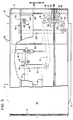
- the cam surface 72 and the stud 70 coact to rotate the bell crank lever 64 in a counterclockwise direction, which performs two functions.
- it acts through a link 74 to operate a pawl 76 which is rotatably mounted on a pivot 78 fixed to the floor or bottom 68 of the casing 21.
- the pawl 76 coacts with a ratchet wheel 80 fixed to an indicator 82.
- the combined ratchet wheel 80 and indicator 82 are rotatably mounted on a shaft 84 fixed to the bottom of the casing 21, and held on the shaft 84 by a fastener 85.
- the crank lever 64 moves a slide member 86 out of the side wall 88 of the casing 21 to coact with an abutment member (not shown) of the ATM 22 to prevent the cassette 20 from being withdrawn from the ATM until the door 30 is closed.
- the door 30 When the cassette 20 is removed from the ATM 22, the door 30 will be closed and the bell crank 64 will be rocked in a clockwise direction, shifting the link 74 to the left as viewed in Fig. 5 and causing the pawl 76 to rock about its pivot 78 in a counterclockwise direction to move the centering tooth 94 into engagement with the ratchet wheel 80, thereby retaining said wheel and the indicator 82 against movement, while the tooth 90 on the pawl 76 is rocked out of engagement with the ratchet wheel 80.
- the indicator is provided around the periphery of its top planar surface with consecutive numbers 96 for indicating the number of times that the door 30 has been opened.
- similar consecutive numbers 98 are provided along the vertical circumferential surface 100 of the indicator 82.
- the numbers 98 are offset by one position from the numbers 96, as best shown in Fig. 8. Openings 102 and 108, in the support structure 54 and the rear wall 106, with a protective window 104 of glass or appropriate transparent material in the rear wall 106, are provided to enable the numbers 96 and 98 to be viewed from the interior and exterior of the cassette 20.
- the indicator When the cassette 20 is filled with currency at a central location, the indicator is reset to a zero position, in a manner which will be subsequently described. Thereafter, each time the door 30 is opened, the pawl 76 coacts with the ratchet wheel 80 to advance the indicator by one position.
- the ratchet wheel 80 would continue to be advanced one position by the pawl 76 each time that the door 30 is opened, and would thus advance through the highest number of the indicator 82 and back to the zero position and beyond. It would thus be simple for a person wishing to obtain unauthorized access to the cassette 20 simply to continue to move the cassette 20 into and out of the ATM 22, thereby in effect erasing the indication on the indicator 82 of an unauthorized entry.
- This indication of unauthorized opening of the cassette is achieved in the present invention by the provision of a projection 110 on the ratchet wheel 80 which rotates with said ratchet wheel.
- a surface 112 on an arm 114 (Figs. 3, 4, 5 and 9) is located in the circular path of movement of the projection 110 when the arm 114 is in a blocking position.
- the arm 114 is mounted for linear sliding movement on a second arm 116 by means of a slot 118 in the arm 114, in which ride a first stud 120 on the arm 116 and a second stud 122 which also serves as a pivot for rotatably mounting the arm 116 on the cassette floor 68.
- a spring 124 extending between projections 126 and 128 of the arms 114 and 116, respectively, urges the arm 114 upward to the right, as viewed in Figs. 3, 4 and 5, toward a position of engagement with the projection ⁇ 110.
- the seal 38 is broken and the lid 34 is opened to add currency to the cassette. Opening of the lid 34 exposes a manually operable handle 146 which extends through an opening 148 in the currency support structure 54, and which is fixed to a lever 130 pivotably mounted on a stud 132 secured to the cassette floor 68.
- the lever 130 is urged in a clockwise direction (with reference to Figs. 3 and 5) by a spring 134 extending between said levers and a stud 136 secured to the cassette floor 68.
- a link 138 couples the lever 130 to the arm 116.
- the handle 146 When it is desired to reset the indicator 82 to its zero position, the handle 146 is grasped and is moved in a direction upward and to the right, as viewed in Fig. 3. This rocks the lever 130 in a counterclockwise direction about its pivot 132 against the force of the spring 134. This movement is transmitted by the link 138 to the arm 116, and rocks it in a counterclockwise direction about the pivot 122.
- the arm 114 which is carried by the arm 116, and the surface 112 on the arm 114, accordingly also are rocked in a counterclockwise direction. This shifts the surface 112 out of the path of movement of the projection 110 on the ratchet wheel 80, and permits the indicator 82 to be set manually to the zero position.
- the cassette 20 after being reloaded with currency and having its indicator 82 reset to zero position, is once again ready to be transported from the central location to an ATM 22, in which it can be placed for the dispensing of currency.
Landscapes
- Physics & Mathematics (AREA)
- General Physics & Mathematics (AREA)
- Sheets, Magazines, And Separation Thereof (AREA)
- Pile Receivers (AREA)
- Control Of Vending Devices And Auxiliary Devices For Vending Devices (AREA)
Claims (7)
Applications Claiming Priority (2)
| Application Number | Priority Date | Filing Date | Title |
|---|---|---|---|
| US715860 | 1985-03-25 | ||
| US06/715,860 US4655391A (en) | 1985-03-25 | 1985-03-25 | Container having tamper-indicating means |
Publications (2)
| Publication Number | Publication Date |
|---|---|
| EP0216823A1 EP0216823A1 (de) | 1987-04-08 |
| EP0216823B1 true EP0216823B1 (de) | 1989-04-26 |
Family
ID=24875772
Family Applications (1)
| Application Number | Title | Priority Date | Filing Date |
|---|---|---|---|
| EP86901714A Expired EP0216823B1 (de) | 1985-03-25 | 1986-02-28 | Wertbehälter mit anzeige unbefugter betätigung |
Country Status (6)
| Country | Link |
|---|---|
| US (1) | US4655391A (de) |
| EP (1) | EP0216823B1 (de) |
| JP (1) | JP2527430B2 (de) |
| CA (1) | CA1257143A (de) |
| DE (1) | DE3663051D1 (de) |
| WO (1) | WO1986005835A1 (de) |
Families Citing this family (14)
| Publication number | Priority date | Publication date | Assignee | Title |
|---|---|---|---|---|
| DE3706829A1 (de) * | 1987-03-03 | 1988-09-15 | Nixdorf Computer Ag | Ausgabeeinheit fuer wertscheine |
| US5049727A (en) * | 1988-12-28 | 1991-09-17 | Pitney Bowes Inc. | Locking device for removable postage meter |
| GB8920940D0 (en) * | 1989-09-15 | 1989-11-01 | Ncr Co | Portable container for valuable items |
| US6293469B1 (en) | 1994-12-20 | 2001-09-25 | Dh Technology Inc. | Transaction printer |
| US5871209A (en) * | 1996-03-01 | 1999-02-16 | Currency Systems International, Inc. | Cassette based document handling system |
| US6109522A (en) * | 1997-11-28 | 2000-08-29 | Diebold, Incorporated | Automated banking machine with self auditing capabilities and system |
| US6027025A (en) * | 1998-03-20 | 2000-02-22 | Skyteller, L.L.C. | Currency storage and dispensing apparatus |
| US6712352B2 (en) | 2000-10-17 | 2004-03-30 | Mars Incorporated | Lockable removable cassette |
| US7694872B2 (en) * | 2002-07-15 | 2010-04-13 | Scheidt & Bachmann, Gmbh | Cashbox and apparatus for emptying the cashbox |
| US7780073B2 (en) * | 2002-12-31 | 2010-08-24 | Diebold Self-Service Systems, Division Of Diebold, Incorporated | Polymer divert cassette for ATM currency |
| US7004383B2 (en) * | 2003-03-10 | 2006-02-28 | Diebold Self-Service Systems, A Division Of Diebold, Incorporated | ATM currency cassette door arrangement |
| GB201609424D0 (en) * | 2016-05-27 | 2016-07-13 | Scotia Safes Ltd | Security apparatus for ATM |
| JP6495873B2 (ja) * | 2016-08-24 | 2019-04-03 | 株式会社栃木屋 | 表示装置 |
| US11247842B2 (en) * | 2018-10-26 | 2022-02-15 | Tranzonic Companies | Hands free disposal unit |
Family Cites Families (18)
| Publication number | Priority date | Publication date | Assignee | Title |
|---|---|---|---|---|
| FR549160A (fr) * | 1922-03-21 | 1923-02-03 | Coffre de sûreté | |
| CH103173A (de) * | 1923-03-26 | 1924-01-16 | Gruenig Jules | Vorrichtung zur Kontrolle des Öffnens von Türen und des Deckels von Behältnissen. |
| DE1276294B (de) * | 1961-12-04 | 1968-08-29 | Robert J Livingston | Verschluss fuer insbesondere Arzneimittel enthaltende Behaeltnisse mit Zaehl- oder Anzeigevorrichtung |
| US3276835A (en) * | 1964-10-28 | 1966-10-04 | Mitchell A Hall | Money box construction |
| GB1442599A (en) * | 1972-07-28 | 1976-07-14 | Armstrong J H G | Containers for substantially planar articles |
| SE391554B (sv) * | 1975-11-17 | 1977-02-21 | Telcefo Security Prod Ab | Sett att forhindra obehorigt utnyttjande av bandspelare jemte anordning for utovande av settet |
| US4186977A (en) * | 1978-10-18 | 1980-02-05 | International Business Machines Corporation | Self-locking depository container |
| JPS5586242U (de) * | 1978-12-06 | 1980-06-14 | ||
| SE445592C (sv) * | 1978-12-08 | 1988-06-21 | De La Rue Syst | Sedelhanteringsapparat med maskinavläsningsbara identifieringsorgan |
| SE429693B (sv) * | 1978-12-08 | 1983-09-19 | De La Rue Syst | Sekerhetskassett |
| GB2039264B (en) * | 1978-12-08 | 1983-09-28 | De La Rue Crosfield | Security cassettes |
| GB2079832B (en) * | 1980-07-14 | 1984-02-22 | Ncr Co | Cassette for currency notes |
| DE3368251D1 (en) * | 1982-06-23 | 1987-01-22 | Univeyor As | An apparatus for rowwise accumulation of roller containers |
| DE3468563D1 (en) * | 1983-02-03 | 1988-02-11 | Ncr Co | Portable container for valuable articles |
| GB2134973B (en) * | 1983-02-03 | 1986-08-20 | Ncr Co | Tamper-indicating containers for valuable articles |
| US4529119A (en) * | 1983-08-12 | 1985-07-16 | Ncr Corporation | Tampering-proof cassette used in a cash dispenser |
| US4529118A (en) * | 1983-08-12 | 1985-07-16 | Ncr Corporation | Tampering-proof cassette for receiving currency deposits and identification cards |
| GB8404364D0 (en) * | 1984-02-20 | 1984-03-28 | De La Rue Syst | Sheet dispensing apparatus |
-
1985
- 1985-03-25 US US06/715,860 patent/US4655391A/en not_active Expired - Lifetime
- 1985-12-31 CA CA000498817A patent/CA1257143A/en not_active Expired
-
1986
- 1986-02-28 EP EP86901714A patent/EP0216823B1/de not_active Expired
- 1986-02-28 JP JP61501476A patent/JP2527430B2/ja not_active Expired - Lifetime
- 1986-02-28 DE DE8686901714T patent/DE3663051D1/de not_active Expired
- 1986-02-28 WO PCT/US1986/000426 patent/WO1986005835A1/en active IP Right Grant
Also Published As
| Publication number | Publication date |
|---|---|
| JP2527430B2 (ja) | 1996-08-21 |
| CA1257143A (en) | 1989-07-11 |
| DE3663051D1 (en) | 1989-06-01 |
| US4655391A (en) | 1987-04-07 |
| JPS62502365A (ja) | 1987-09-10 |
| WO1986005835A1 (en) | 1986-10-09 |
| EP0216823A1 (de) | 1987-04-08 |
Similar Documents
| Publication | Publication Date | Title |
|---|---|---|
| US4659008A (en) | Tampering-proof cassette used in a cash dispenser | |
| US4529119A (en) | Tampering-proof cassette used in a cash dispenser | |
| EP0157510B1 (de) | System mit auswechselbaren Banknotenkassetten für automatische Bankschalter | |
| US4438704A (en) | Cassette for currency notes or other valuable articles | |
| EP0588909B1 (de) | Eine verschliessbare, abnehmbare kassette | |
| US4529118A (en) | Tampering-proof cassette for receiving currency deposits and identification cards | |
| EP0216823B1 (de) | Wertbehälter mit anzeige unbefugter betätigung | |
| US4341100A (en) | Portable certificate magazine | |
| US4370006A (en) | Banking media security mechanism for automatic banking machines | |
| US4552075A (en) | Secure container, for example for banknotes | |
| EP0166041B1 (de) | Auswechselbare Banknotenkassette für automatischen Bankschalter | |
| US4508260A (en) | Portable container for valuable articles | |
| EP0137013B1 (de) | Tragbare behälter für wertsachen | |
| JP2000194915A (ja) | 自動販売機の硬貨回収用金庫及びスタンド型自動販売機 | |
| US3749218A (en) | Bag vending machine | |
| JP2661938B2 (ja) | 郵便物収納装置 | |
| JPH03136190A (ja) | 貴重品用ポータブル・コンテナ | |
| JPH0547262U (ja) | 収納ユニットのロック機構 |
Legal Events
| Date | Code | Title | Description |
|---|---|---|---|
| PUAI | Public reference made under article 153(3) epc to a published international application that has entered the european phase |
Free format text: ORIGINAL CODE: 0009012 |
|
| AK | Designated contracting states |
Kind code of ref document: A1 Designated state(s): DE FR GB |
|
| 17P | Request for examination filed |
Effective date: 19870327 |
|
| DET | De: translation of patent claims | ||
| 17Q | First examination report despatched |
Effective date: 19880111 |
|
| GRAA | (expected) grant |
Free format text: ORIGINAL CODE: 0009210 |
|
| AK | Designated contracting states |
Kind code of ref document: B1 Designated state(s): DE FR GB |
|
| REF | Corresponds to: |
Ref document number: 3663051 Country of ref document: DE Date of ref document: 19890601 |
|
| ET | Fr: translation filed | ||
| PLBE | No opposition filed within time limit |
Free format text: ORIGINAL CODE: 0009261 |
|
| STAA | Information on the status of an ep patent application or granted ep patent |
Free format text: STATUS: NO OPPOSITION FILED WITHIN TIME LIMIT |
|
| 26N | No opposition filed | ||
| REG | Reference to a national code |
Ref country code: GB Ref legal event code: 732E |
|
| REG | Reference to a national code |
Ref country code: FR Ref legal event code: TP |
|
| REG | Reference to a national code |
Ref country code: GB Ref legal event code: IF02 |
|
| REG | Reference to a national code |
Ref country code: GB Ref legal event code: 746 Effective date: 20011217 |
|
| PGFP | Annual fee paid to national office [announced via postgrant information from national office to epo] |
Ref country code: GB Payment date: 20021218 Year of fee payment: 18 |
|
| PGFP | Annual fee paid to national office [announced via postgrant information from national office to epo] |
Ref country code: FR Payment date: 20030129 Year of fee payment: 18 |
|
| PGFP | Annual fee paid to national office [announced via postgrant information from national office to epo] |
Ref country code: DE Payment date: 20030310 Year of fee payment: 18 |
|
| PG25 | Lapsed in a contracting state [announced via postgrant information from national office to epo] |
Ref country code: GB Free format text: LAPSE BECAUSE OF NON-PAYMENT OF DUE FEES Effective date: 20040228 |
|
| PG25 | Lapsed in a contracting state [announced via postgrant information from national office to epo] |
Ref country code: DE Free format text: LAPSE BECAUSE OF NON-PAYMENT OF DUE FEES Effective date: 20040901 |
|
| GBPC | Gb: european patent ceased through non-payment of renewal fee | ||
| PG25 | Lapsed in a contracting state [announced via postgrant information from national office to epo] |
Ref country code: FR Free format text: LAPSE BECAUSE OF NON-PAYMENT OF DUE FEES Effective date: 20041029 |
|
| REG | Reference to a national code |
Ref country code: FR Ref legal event code: ST |