EP0216718A2 - Mehrpunktsicherheitsverriegelung für Türen oder dergleichen - Google Patents
Mehrpunktsicherheitsverriegelung für Türen oder dergleichen Download PDFInfo
- Publication number
- EP0216718A2 EP0216718A2 EP86430031A EP86430031A EP0216718A2 EP 0216718 A2 EP0216718 A2 EP 0216718A2 EP 86430031 A EP86430031 A EP 86430031A EP 86430031 A EP86430031 A EP 86430031A EP 0216718 A2 EP0216718 A2 EP 0216718A2
- Authority
- EP
- European Patent Office
- Prior art keywords
- bolt
- closing device
- locking
- safety closing
- lock
- Prior art date
- Legal status (The legal status is an assumption and is not a legal conclusion. Google has not performed a legal analysis and makes no representation as to the accuracy of the status listed.)
- Withdrawn
Links
- 230000000903 blocking effect Effects 0.000 claims description 13
- 230000000694 effects Effects 0.000 claims description 3
- 230000001681 protective effect Effects 0.000 claims description 3
- 230000005484 gravity Effects 0.000 claims description 2
- 238000009434 installation Methods 0.000 abstract description 3
- 229910000831 Steel Inorganic materials 0.000 description 2
- 210000000056 organ Anatomy 0.000 description 2
- 239000010959 steel Substances 0.000 description 2
- 230000000712 assembly Effects 0.000 description 1
- 238000000429 assembly Methods 0.000 description 1
- 238000010276 construction Methods 0.000 description 1
- 239000002184 metal Substances 0.000 description 1
- 239000002699 waste material Substances 0.000 description 1
- 238000003466 welding Methods 0.000 description 1
Images
Classifications
-
- E—FIXED CONSTRUCTIONS
- E05—LOCKS; KEYS; WINDOW OR DOOR FITTINGS; SAFES
- E05B—LOCKS; ACCESSORIES THEREFOR; HANDCUFFS
- E05B63/00—Locks or fastenings with special structural characteristics
- E05B63/24—Arrangements in which the fastening members which engage one another are mounted respectively on the wing and the frame and are both movable, e.g. for release by moving either of them
- E05B63/242—Auxiliary bolts on the frame, actuated by bolts on the wing, or vice versa
Definitions
- the present invention relates to a safety locking device with multiple locking points, for doors or other openings.
- safety closing devices with multiple locking points comprising a safety lock intended to be installed on the leaf of an opening such as a door, and provided with a plurality of horizontal and vertical bolts called to engage, in the locked position, in a corresponding number of strikes fixed on the frame of said opening.
- Such devices have the drawbacks of being complex and expensive, and of requiring a relatively long exposure time, since it is not only necessary to install the lock and the fixing and guiding collars of its bolts constituted by long bars, on the leaf of the opening, but also a plurality of strikes corresponding to the number of bolts, on three or four sides of the frame of said opening.
- it is mandatory to change the latter which is generally expensive and whose disposal is an unfortunate waste.
- An object pursued by the invention is therefore to remedy these drawbacks while allowing effective blocking at several points of the leaf of the opening, thereby offering very good resistance to burglary attempts.
- a safety closing device comprising a locking mechanism intended and able to be installed on one of the uprights of the fixed frame or fixed frame of an opening and comprising blocking members capable of being actuated using the bolt of a safety lock or bolt installed on the leaf of said opening.
- the locking mechanism comprises at least two rocking locking latches spaced apart and connected, each by means of an articulation, to a drive rod capable of being actuated by means of the bolt of the lock.
- the locking mechanism comprises a pivoting lever provided with an operating finger capable of being pushed back by the bolt of a safety lock or bolt installed on the leaf of an opening, said pivoting lever being connected , by means of an articulation, to the drive rods of the tilting blocking latches.
- At least one of the two drive rods is also connected, by means of an articulation, to one of the ends of a third drive rod whose opposite end is secured, by means of a joint, to a third tilting blocking latch.
- the locking mechanism further comprises a keeper capable of serving as a housing for the bolt of a safety lock or bolt installed on the leaf of an opening.
- the safety closure device according to the invention has in particular the advantages of being effective, simple, relatively inexpensive, and of being able to be installed quickly due to the fact that this installation only requires the fixing of a safety lock or bolt classic on the opening leaf and compact locking mechanism on one of the uprights of the sleeping frame or jamb of said opening.
- the safety closing device according to the invention operates with a conventional safety lock or bolt, there is no obligation, when installed on openings with which the leaf is already equipped remove such a lock or security lock, which can therefore remain in place. In such situations, it is only necessary to fix the locking mechanism on the corresponding upright of the frame. In this case, the fixing of this mechanism can be carried out easily and quickly, so that the cost price of this equipment and its installation is relatively low compared to the cost of existing safety locking systems with multiple locking points. .
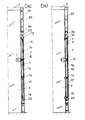
- This device comprises a locking mechanism shown in detail in FIGS. 3 to 8.
- this mechanism comprises a plate 1 constituted by a robust metal strip (steel, for example).
- This monobloc plate carries the various organs of the locking mechanism and it is provided with a first series of holes 2 allowing its fixing, by means of screws and in a vertical position, on the internal face of the upright 3a of the fixed frame or fixed frame 3 of the opening opposite the second upright fitted with hinges carrying the leaf 4 of said opening.
- the length of the plate 1 can correspond substantially to the height of the leaf 4 or be less than the latter.
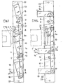
- a lever 6 On the front face of the plate 1, is mounted, with a pivoting ability and by means of a fixed axis 5, a lever 6 provided with an operating finger 6a comprising one end curved forward and disposed au- below the hinge pin 5 of said lever.
- This operating finger 6a is intended to be pushed back by the bolt 7a of a lock or a bolt 7 of the conventional or other type, installed on the leaf 4 of the opening; this lock can be the security lock already fitted to the leaf, in the constructions already carried out.
- the bolt 7a and the operating finger 6a are arranged opposite one another and, taking into account the position of said finger, it is understood that when it is pushed back under the action of said bolt, the lever 6 is pivoted towards the top.
- pivoting lever 6 On the pivoting lever 6, are articulated, preferably by means of a movable common axis 8, one of the ends of two rods or drive rods 9, 10, for example constituted by flat steel bars.
- connecting rods 9, 10 are articulated, by means of movable pins 11, 12, respectively, on tilting locking latches 13, 14, the latter being mounted, with a pivotability, using fixed axes 15, 16, respectively, on plate 1.
- At least one of the drive rods 9, 10, is connected, by means of a joint and by its end opposite to that which is subject to the lever 6, to one of the ends of a other drive rod 17.
- the drive rods 10 and 17 are articulated by means of a common axis, constituted by the articulation axis 12 of the intermediate rod 10 on the tilting blocking latch 14.
- the other end of the link 17 is articulated, by means of a movable axis 18, on a third tilting blocking latch 19 mounted with a pivotability, by means of a fixed axis 20, on the plate 1 .
- the plate 1 also carries a keeper 21 constituted by a robust piece in the form of a bridge spanning the pivoting lever 6 and fixed to said plate by welding or otherwise.
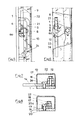
- the locking mechanism further comprises a robust protective cover 22 in the form of a U in which the various organs described above of said mechanism are housed and which is fixed vertically by means of screws passing through a second series of holes 23 formed in the plate. 1, on the upright 3a of the sleeping frame or jamb of the opening.
- This cover 22 has lateral openings 24 for the passage of the bolt 7a of the lock 7 and tilting locking latches 13, 14, 19.
- a stop is provided in order to prevent the movable articulation axes 8, 11, 12, 18 of the locking mechanism from occupying a position too close to the vertical passing through the fixed pivot axes 15, 16, 20 latches for blocking said mechanism, or pivoting beyond this vertical, which would hinder or prohibit the operation of the latter.
- This stop is, for example, constituted by the head 20a of the fixed axis 20 against which abuts one of the sides of the lower link 17, in the low rest position.
Landscapes
- Physics & Mathematics (AREA)
- Electromagnetism (AREA)
- Engineering & Computer Science (AREA)
- Structural Engineering (AREA)
- Operating, Guiding And Securing Of Roll- Type Closing Members (AREA)
Applications Claiming Priority (2)
| Application Number | Priority Date | Filing Date | Title |
|---|---|---|---|
| FR8513370 | 1985-09-06 | ||
| FR8513370A FR2587056A1 (fr) | 1985-09-06 | 1985-09-06 | Dispositif de fermeture de securite a points de blocage multiples, pour portes ou autres ouvertures |
Publications (2)
| Publication Number | Publication Date |
|---|---|
| EP0216718A2 true EP0216718A2 (de) | 1987-04-01 |
| EP0216718A3 EP0216718A3 (de) | 1988-03-23 |
Family
ID=9322749
Family Applications (1)
| Application Number | Title | Priority Date | Filing Date |
|---|---|---|---|
| EP86430031A Withdrawn EP0216718A3 (de) | 1985-09-06 | 1986-09-05 | Mehrpunktsicherheitsverriegelung für Türen oder dergleichen |
Country Status (2)
| Country | Link |
|---|---|
| EP (1) | EP0216718A3 (de) |
| FR (1) | FR2587056A1 (de) |
Cited By (1)
| Publication number | Priority date | Publication date | Assignee | Title |
|---|---|---|---|---|
| GB2232188A (en) * | 1989-04-27 | 1990-12-05 | Fireglas Doors Limited | Improvements in or relating to fire doors |
Family Cites Families (1)
| Publication number | Priority date | Publication date | Assignee | Title |
|---|---|---|---|---|
| FR7235E (fr) * | 1906-10-27 | 1907-06-13 | Abel Raimond Alexandre Gerard | Fermeture de sureté |
-
1985
- 1985-09-06 FR FR8513370A patent/FR2587056A1/fr not_active Withdrawn
-
1986
- 1986-09-05 EP EP86430031A patent/EP0216718A3/de not_active Withdrawn
Cited By (1)
| Publication number | Priority date | Publication date | Assignee | Title |
|---|---|---|---|---|
| GB2232188A (en) * | 1989-04-27 | 1990-12-05 | Fireglas Doors Limited | Improvements in or relating to fire doors |
Also Published As
| Publication number | Publication date |
|---|---|
| EP0216718A3 (de) | 1988-03-23 |
| FR2587056A1 (fr) | 1987-03-13 |
Similar Documents
| Publication | Publication Date | Title |
|---|---|---|
| FR2813631A1 (fr) | Vehicule automobile avec une porte battante et une porte coulissante independantes l'une de l'autre | |
| FR2576961A1 (fr) | Mecanisme d'assistance a la fermeture d'une porte d'un vehicule automobile | |
| EP0219589B1 (de) | Falttür | |
| EP0216718A2 (de) | Mehrpunktsicherheitsverriegelung für Türen oder dergleichen | |
| FR2861789A1 (fr) | Serrure anti-panique multipoint reversible | |
| EP0360696B1 (de) | Verriegelungsvorrichtung für eine zweiflügelige Tür | |
| FR2681368A1 (fr) | Dispositif de fermeture pour porte retournable, et armoire dont la porte est equipee d'un tel dispositif de fermeture, notamment pour appareillages electriques . | |
| FR2817902A1 (fr) | Dispositif de condamnation securisee de l'acces a une echelle a crinoline | |
| FR2716916A1 (fr) | Dispositif de verrouillage de fenêtre ou de porte. | |
| FR2814190A1 (fr) | Mecanisme de manoeuvre de porte | |
| EP0754920B1 (de) | Vorrichtung zum Öffnen oder Schliessen einer Tür für einen Raum und Backofen mit einer solchen Vorrichtung | |
| FR2601062A1 (fr) | Loquet de verrouillage a pene pivotant, destine notamment a une partie comportant une fermeture antipanique. | |
| WO1991014592A1 (fr) | Perfectionnement aux dispositifs permettant le transport de charges longues dans des vehicules automobiles utilitaires | |
| FR2701987A1 (fr) | Dispositif de fermeture de porte. | |
| EP0504045B1 (de) | Verschlusseinrichtung für eine umwendbare Tür, und Schrank mit dieser Verschlusseinrichtung | |
| FR2601063A1 (fr) | Coffre principal destine a etre integre dans une fermeture anti-panique du type a barre d'enfoncement dite " push-bar ". | |
| FR2660010A1 (fr) | Dispositif de securite et de secours pour l'ouverture partielle de portes basculantes de garages et similaires. | |
| FR2610034A3 (fr) | Dispositif de verrouillage d'un ouvrant par tringle coulissante adaptable a un verrou targette monobloc | |
| FR2690478A1 (fr) | Foyer de cheminée à porte pivotante et escamotable. | |
| EP0267060A1 (de) | Verriegelungsvorrichtung für Briefkasten mit Drehriegelplatte | |
| FR2740752A1 (fr) | Carrosserie comportant un soubassement, un pavillon et au moins une porte coulissante et deux portes battantes | |
| FR2677337A1 (fr) | Dispositif de fermeture multipoints pour porte de boite aux lettres. | |
| EP0013228A1 (de) | Vorrichtung zum Feststellen eines Fensters in einer Offenstellung | |
| FR2765612A1 (fr) | Limiteur d'ouverture pour baies coulissantes | |
| FR2633968A1 (fr) | Dispositif de fixation et de verrouillage automatique pour barres de securite sur des elements de fermetures du type volets, persiennes, portes et similaires |
Legal Events
| Date | Code | Title | Description |
|---|---|---|---|
| PUAI | Public reference made under article 153(3) epc to a published international application that has entered the european phase |
Free format text: ORIGINAL CODE: 0009012 |
|
| AK | Designated contracting states |
Kind code of ref document: A2 Designated state(s): AT BE CH DE GB IT LI LU NL SE |
|
| PUAL | Search report despatched |
Free format text: ORIGINAL CODE: 0009013 |
|
| AK | Designated contracting states |
Kind code of ref document: A3 Designated state(s): AT BE CH DE GB IT LI LU NL SE |
|
| STAA | Information on the status of an ep patent application or granted ep patent |
Free format text: STATUS: THE APPLICATION IS DEEMED TO BE WITHDRAWN |
|
| 18D | Application deemed to be withdrawn |
Effective date: 19880926 |