EP0216702A2 - Method and plant for tartars separation - Google Patents
Method and plant for tartars separation Download PDFInfo
- Publication number
- EP0216702A2 EP0216702A2 EP86402046A EP86402046A EP0216702A2 EP 0216702 A2 EP0216702 A2 EP 0216702A2 EP 86402046 A EP86402046 A EP 86402046A EP 86402046 A EP86402046 A EP 86402046A EP 0216702 A2 EP0216702 A2 EP 0216702A2
- Authority
- EP
- European Patent Office
- Prior art keywords
- draft tube
- cylindrical
- crystallizer
- zone
- stirrer
- Prior art date
- Legal status (The legal status is an assumption and is not a legal conclusion. Google has not performed a legal analysis and makes no representation as to the accuracy of the status listed.)
- Granted
Links
Images

Classifications
-
- C—CHEMISTRY; METALLURGY
- C12—BIOCHEMISTRY; BEER; SPIRITS; WINE; VINEGAR; MICROBIOLOGY; ENZYMOLOGY; MUTATION OR GENETIC ENGINEERING
- C12H—PASTEURISATION, STERILISATION, PRESERVATION, PURIFICATION, CLARIFICATION OR AGEING OF ALCOHOLIC BEVERAGES; METHODS FOR ALTERING THE ALCOHOL CONTENT OF FERMENTED SOLUTIONS OR ALCOHOLIC BEVERAGES
- C12H1/00—Pasteurisation, sterilisation, preservation, purification, clarification, or ageing of alcoholic beverages
- C12H1/02—Pasteurisation, sterilisation, preservation, purification, clarification, or ageing of alcoholic beverages combined with removal of precipitate or added materials, e.g. adsorption material
- C12H1/06—Precipitation by physical means, e.g. by irradiation, vibrations
- C12H1/08—Precipitation by physical means, e.g. by irradiation, vibrations by heating
-
- B—PERFORMING OPERATIONS; TRANSPORTING
- B01—PHYSICAL OR CHEMICAL PROCESSES OR APPARATUS IN GENERAL
- B01D—SEPARATION
- B01D9/00—Crystallisation
- B01D9/0004—Crystallisation cooling by heat exchange
- B01D9/0013—Crystallisation cooling by heat exchange by indirect heat exchange
-
- B—PERFORMING OPERATIONS; TRANSPORTING
- B01—PHYSICAL OR CHEMICAL PROCESSES OR APPARATUS IN GENERAL
- B01D—SEPARATION
- B01D9/00—Crystallisation
- B01D9/0036—Crystallisation on to a bed of product crystals; Seeding
Definitions
- This invention relates to a method and an apparatus for removing tartar from wine or grape juice in order to prevent tartar precipitation in the bottled product. More particularly, it relates to a technique for separating tartar dissolved in a liquid by crystallizing the tartar with seed crystals. The technique provides chemically stabilized juice and wine products and maintains their commercial value.
- Bottled wine often has tartar precipitates in the form of crystals on the bottom of the bottle. Such precipitates occur between bottling and consumption. These precipitates make the product unattractive to consumers.
- Tartar precipitates have been removed by cooling, cation exchange, anion exchange, reverse osmosis, and electrodialysis. Also, tartar precipitates have been inhibited by the use of additives.
- a cooling method based on the primary nucleation of potassium hydrogentartrate, which is a major component of tartar, is known.
- this method requires the maintenance of supersaturated solutions for a long time to produce natural nucleation.
- it if cannot serve market demand immediately, and it requires a large initial investment for cooling equipment and storage equipment.
- Another cooling method is known which comprises increasing tartar concentration by freezing and thickening wine to accelerate nucleation.
- this method cannot steadily crystallize and remove tartar and requires additional freezing equipment. This still further increases initial equipment costs.
- the second method is disclosed, for example, in Japanese Examined Patent Publication No. 5157/1981, issued to Henkel and Co.
- This publication discloses a process in which tartar is extracted from wine through the adhesion of the tartar on carriers made of fiber, etc.
- the carriers carry the tartar crystals to promote the extraction.
- DTB crystallizers Draft tube baffled crystallizers
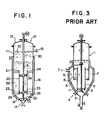
- FIG. 3 A typical DTB crystallizer is illustrated in Figure 3.
- the numeral 1 identifies a DTB crystallizer equipped with a draft tube 2 centered in the lower half of the DTB crystallizer 1.
- a propeller 3 is mounted at the bottom of the draft tube 2.
- the propeller 3 is driven by a motor M connected to the propeller 3 via a shaft.
- An interposed tube 8 surrounds the draft tube 2, and a vessel 9 surrounds the interposed tube 8. Rotation of the propeller 3 forces an upward flow of liquid introduced from an inlet 4 into the draft tube 2, downward flow of the liquid between the interposed tube 8 and the draft tube 2, and upward flow of the liquid toward an outlet 7 between the interposed tube 8 and the vessel 9.
- the numeral 5 identifies a classification leg for separation. Crystals grow inside the draft tube 2 and between the draft tube 2 and the interposed tube 8. These two volumes form a crystallization zone. A space 6 between the interposed tube 8 and the vessel 9 forms a fine trap zone F from which fine crystals on the upward flow are discharged through the outlet 7. Crystals which have grown to some extent remain in the crystallization zone and are allowed to grow uniformly and larger. It is to be understood that the feature of the DTB crystallizer resides in that the interposed tube 8, which extends inside the crystallization zone, functions as a baffle, facilitating the separation of fine crystals from grown crystals. A cooling jacket J to which coolant is supplied is provided on the vessel 9.
- DTB crystallizers are not suitable to tartar crystallization of wine or grape juice, since the concept of the draft and the classification for such crystals is different from that of other fields.
- conventional DTB crystallizers are expensive due to their complicated structure. Furthermore, the complicated structures make it difficult to clean the inside of the crystallizers in place, which is not favorable from the viewpoint of sanitation.
- a principal feature of the present invention resides in the employment of a draft tube having a height which is one-half or less the height of the crystallizer.
- the draft tube is centered in the inside of the crystallizer.
- a crystallization section includes a means for circulating source liquid for the tartar crystallization.
- the crystallizer is designed to provide a downward flow inside the draft tube and an upward flow at a low rate outside the draft tube.
- a calming section is located above the crystallization section, but it is not greatly influenced by the circulation, so that classification may be effected in the calming section.
- tartar crystallization is promoted concurrently with classification of the crystals owing to the presence of a crystallization section and a calming section in a crystallizer in place of the fines trap of the DTB crystallizer.
- a crystallization section and a calming section in a crystallizer in place of the fines trap of the DTB crystallizer.
- the present invention provides an apparatus for removing tartar which is simple in structure, low in cost, and the inside of which is easy to clean in place.
- the numeral 10 generally indicates a crystallizer according to the present invention.
- the crystallizer 10 is preferably made of stainless steel. It comprises an upright cylinder 11 which is closed by a conical portion 12 on the bottom and which is attached to a cap portion 13 on the top.
- the conical portion 12 has an axial inlet 14 at its bottom.
- the cylinder 11 has a radial outlet 15 on its upper wall.
- the crystallizer 10 is provided on its exterior wall with a cooling jacket 16 which extends from the upper wall of the cylinder 11 through the conical portion 12.
- the cooling jacket 16 is supplied with coolant and has a capacity to keep the temperature of the precooled source liquid at 0° to -3°C.
- the outlet 15 limits the height of the liquid in the crystallizer 10.
- the numeral 20 indicates a cylindrical draft tube made of stainless steel.
- the top and bottom ends 21, 22 of the draft tube 20 are open.
- the draft tube 20 is supported in the lower half of the crystallizer 10 by supporting members 23 and 24 spaced axially of the draft tube 20.
- the supporting members 23 and 24 are sized and shaped so that they do not appreciably effect the upward flow of the liquid during use of the crystallizer 10.
- the draft tube 20 is fixed on the interior wall of the cylinder 11 so as to locate the draft tube 20 coaxially of the cylinder 11.
- the height of the draft tube 20 is preferably 1/2 to 1/4 the height of the crystallizer 10.
- the diameter of the draft tube 20 is preferably about 1/2 to 1/3 the diameter of the cylinder 11.
- the numeral 30 indicates a stirrer that comprises a shaft 31 and propellers 32, 33, and 34.
- the shaft 31 extends along the common axis of the cylinder 11 and the draft tube 20 from the outside of the cap portion 13 to the bottom of the conical portion 12 and is rotatably supported at the top of the cap portion 13.
- the propeller 32 is arranged at the bottom end of the shaft 31.
- the propeller 33 is mounted on the bottom portion of the shaft 31 surrounded by the draft tube 20, and the propeller 34 is mounted on the top portion of the shaft 31 surrounded by the draft tube 20.
- the stirrer 30 is driven via reduction gears by a motor M mounted on the top of the cap portion 13.
- Rotation of the propeller 32 makes liquid in a volume 35 bounded by the conical portion 12 and the supporting member 23 flow upwardly through the supporting member 23, an annular zone 36 defined by the upright cylinder 11 and the draft tube 20, and the supporting member 24 into a calming zone 37.
- Rotation of the propellers 33, 34 makes liquid inside the draft tube 20 flow downwardly into the volume 35.
- the dimensions of the draft tube 20 are determined so that liquid in the bottom end 22 of the draft tube 20 flows outwardly and joins the upward flow to the annular zone 36.
- some of the liquid flowing upwardly through the annular zone 34 is drawn inwardly over the upper end of the draft tube 20 and is forced back through the draft tube 20 without interacting significantly with the liquid in the calming zone 37.
- a circulation of liquid in the crystallizer 10 is faciliated.
- the circulation through the annular zone 36 forms a crystallization section, while the calming zone 37 is formed above the circulation.
- the two sections in the crystallizer make it easier to separate crystals from liquid.
- seed crystals of tartar To source liquid of wine or grape juice in the cylinder 11 is added seed crystals of tartar. Although the amount of the seed crystals varies depending on concentration of source liquid and the temperature in the crystallizer 10 cooled by the cooling jacket 16, the following values may serve as a guide: 7-8 grams of seed crystals per liter of source liquid at a temperature of about 0°C and 3-4 grams per liter of source liquid at a temperature of about -3°C. That is, the approximate range of concentration is 3-8 grams per liter at a temperature range of between -3°C and 0°C.
- the amount of seed is commonly expressed as the concentration of potassium hydrogentartrate in the source liquid.
- the saturation temperature of the source liquid may be measured, since determination of the concentration is complicated.
- the preferable amount of seed crystals can be expressed as ⁇ 5°C of the lowering of the saturation temperature.
- the stirrer 30 is rotated at 100 rpm or less.
- the rate of the upward flow between the draft tube 20 and the cylinder 11 is lower than the rate of the downward flow through the draft tube 20 (for example, 0.6 m/hr), since the cross sectional area of the annular zone 36 is larger than the cross sectional area of the draft tube 20.
- the calming zone 37 above the draft tube 20 effects classification, since it is little influenced by the circulation around the draft tube 20.
- the liquid from which tartar crystals have been removed overflows outside via the outlet 15 as fresh source liquid is supplied to the volume 35 from the inlet 14.
- crystals grow around seed crystals as a core during the residence time in the annular zone 36 and in the draft tube 20.
- the crystals in the volume 35 are conveyed by the upward flow caused by the propeller 32 without precipitating on the bottom of the crystallizer 10.
- the crystals in the upward flow join the downward flow in the draft tube 20 below the calming zone 37 because of the tendency of the crystals to sink downwardly in the liquid.
- the crystals grown uniformly.
- the circulation occurs only in the vicinity of the draft tube 20 even when the downward force caused by the propellers 33 and 34 is varied, and the circulation does not significantly disturb the calming zone 37.
- the calming zone 37 has a function similar to the fines trap F of the typical crystallizer of Figure 3.
Abstract
Description
- This invention relates to a method and an apparatus for removing tartar from wine or grape juice in order to prevent tartar precipitation in the bottled product. More particularly, it relates to a technique for separating tartar dissolved in a liquid by crystallizing the tartar with seed crystals. The technique provides chemically stabilized juice and wine products and maintains their commercial value.
- Bottled wine often has tartar precipitates in the form of crystals on the bottom of the bottle. Such precipitates occur between bottling and consumption. These precipitates make the product unattractive to consumers.
- Various methods have been proposed for preventing tartar precipitates. Tartar precipitates have been removed by cooling, cation exchange, anion exchange, reverse osmosis, and electrodialysis. Also, tartar precipitates have been inhibited by the use of additives.
- Of the above methods, the cooling methods have been commonly used. The other methods have not been used commercially, since they suffer from various disadvantages.
- A cooling method based on the primary nucleation of potassium hydrogentartrate, which is a major component of tartar, is known. However, this method requires the maintenance of supersaturated solutions for a long time to produce natural nucleation. Thus, if cannot serve market demand immediately, and it requires a large initial investment for cooling equipment and storage equipment.
- Another cooling method is known which comprises increasing tartar concentration by freezing and thickening wine to accelerate nucleation. However, this method cannot steadily crystallize and remove tartar and requires additional freezing equipment. This still further increases initial equipment costs.
- To accelerate natural crystal growth, some cooling methods have been proposed that comprise growing tartar crystals by adding tartar seed crystals to the source liquid of wine, and thereafter separating the tartar crystals. These seeding methods are divided into two categories: A first contact method and a second carrier adhesion method. The first method is disclosed, for example, in West German Patent DE 3244221C1 issued to Westfaria Co. This publication discloses a process in which seed crystals of potassium hydrogentartrate and dipotassium DL-tartrate are added to precipitate and remove calcium ions which inhibit the growth of tartar crystals. In Japanese Examined Patent Publication No. 39157/1982, issued to Henkel and Co., a process is disclosed in which calcium carbonate is employed as the seed crystal material. The second method is disclosed, for example, in Japanese Examined Patent Publication No. 5157/1981, issued to Henkel and Co. This publication discloses a process in which tartar is extracted from wine through the adhesion of the tartar on carriers made of fiber, etc. The carriers carry the tartar crystals to promote the extraction.
- Draft tube baffled crystallizers (hereinafter referred to as DTB crystallizers) have been used in general crystallization processes. A typical DTB crystallizer is illustrated in Figure 3. In Figure 3, the numeral 1 identifies a DTB crystallizer equipped with a
draft tube 2 centered in the lower half of the DTB crystallizer 1. Apropeller 3 is mounted at the bottom of thedraft tube 2. Thepropeller 3 is driven by a motor M connected to thepropeller 3 via a shaft. An interposedtube 8 surrounds thedraft tube 2, and a vessel 9 surrounds the interposedtube 8. Rotation of thepropeller 3 forces an upward flow of liquid introduced from aninlet 4 into thedraft tube 2, downward flow of the liquid between the interposedtube 8 and thedraft tube 2, and upward flow of the liquid toward anoutlet 7 between the interposedtube 8 and the vessel 9. - The
numeral 5 identifies a classification leg for separation. Crystals grow inside thedraft tube 2 and between thedraft tube 2 and the interposedtube 8. These two volumes form a crystallization zone. Aspace 6 between the interposedtube 8 and the vessel 9 forms a fine trap zone F from which fine crystals on the upward flow are discharged through theoutlet 7. Crystals which have grown to some extent remain in the crystallization zone and are allowed to grow uniformly and larger. It is to be understood that the feature of the DTB crystallizer resides in that the interposedtube 8, which extends inside the crystallization zone, functions as a baffle, facilitating the separation of fine crystals from grown crystals. A cooling jacket J to which coolant is supplied is provided on the vessel 9. - As stated above, some of the salient disadvantages of the known cooling methods are that they require expensive equipment for cooling, storage, and concentration; that they do not operate steadily; and that they take a long time to accomplish detartarification because they are based on natural nucleation.
- The methods based on cation exchange, anion exchange, reverse osmosis, electrodialysis, or inhibitors also suffer from salient disadvantages that prevent their use on an industrial scale. Even in the field of the seeding method (which is pertinent to the present invention), there are problems due to the requirement to add additives to precipitate calcium ions, which inhibit tartar crystallization (as in the above German Patent), due to the requirement for supply carriers to promote contact between seed and liquid.
- To solve the above disadvantages, the application of DTB crystallizers was examined. However, conventional DTB crystallizers are not suitable to tartar crystallization of wine or grape juice, since the concept of the draft and the classification for such crystals is different from that of other fields. In addition, conventional DTB crystallizers are expensive due to their complicated structure. Furthermore, the complicated structures make it difficult to clean the inside of the crystallizers in place, which is not favorable from the viewpoint of sanitation.
- It is the principal object of the present invention to provide a method and an apparatus for removing tartar in the form of crystals from wine or grape juice in a crystallizer by using seed crystals. This invention eliminates or greatly ameliorates the drawbacks discussed above.
- A principal feature of the present invention resides in the employment of a draft tube having a height which is one-half or less the height of the crystallizer. The draft tube is centered in the inside of the crystallizer. A crystallization section includes a means for circulating source liquid for the tartar crystallization. The crystallizer is designed to provide a downward flow inside the draft tube and an upward flow at a low rate outside the draft tube. A calming section is located above the crystallization section, but it is not greatly influenced by the circulation, so that classification may be effected in the calming section.
- According to the present invention, tartar crystallization is promoted concurrently with classification of the crystals owing to the presence of a crystallization section and a calming section in a crystallizer in place of the fines trap of the DTB crystallizer. Thus, it is possible to continuously obtain product from which tartar has been removed.
- The present invention provides an apparatus for removing tartar which is simple in structure, low in cost, and the inside of which is easy to clean in place.
- According to a preferred embodiment of the present invention, it is possible to crystallize tartar in one hour of residence time of the source liquid in the crystallizer.
-
- Figure 1 is a diagrammatic illustration of a preferred embodiment of the crystallizer according to the present invention.
- Figure 2 is a graph which shows the results of an experiment conducted using the crystallizer of Figure 1.
- Figure 3 is a diagrammatic illustration of a conventional DTB crystallizer.
- In Figure 1, the numeral 10 generally indicates a crystallizer according to the present invention. The
crystallizer 10 is preferably made of stainless steel. It comprises an upright cylinder 11 which is closed by a conical portion 12 on the bottom and which is attached to acap portion 13 on the top. The conical portion 12 has anaxial inlet 14 at its bottom. The cylinder 11 has aradial outlet 15 on its upper wall. Thecrystallizer 10 is provided on its exterior wall with a coolingjacket 16 which extends from the upper wall of the cylinder 11 through the conical portion 12. The coolingjacket 16 is supplied with coolant and has a capacity to keep the temperature of the precooled source liquid at 0° to -3°C. Theoutlet 15 limits the height of the liquid in thecrystallizer 10. - The numeral 20 indicates a cylindrical draft tube made of stainless steel. The top and bottom ends 21, 22 of the
draft tube 20 are open. Thedraft tube 20 is supported in the lower half of thecrystallizer 10 by supportingmembers draft tube 20. The supportingmembers crystallizer 10. Thedraft tube 20 is fixed on the interior wall of the cylinder 11 so as to locate thedraft tube 20 coaxially of the cylinder 11. The height of thedraft tube 20 is preferably 1/2 to 1/4 the height of thecrystallizer 10. The diameter of thedraft tube 20 is preferably about 1/2 to 1/3 the diameter of the cylinder 11. - The numeral 30 indicates a stirrer that comprises a shaft 31 and
propellers draft tube 20 from the outside of thecap portion 13 to the bottom of the conical portion 12 and is rotatably supported at the top of thecap portion 13. Thepropeller 32 is arranged at the bottom end of the shaft 31. Thepropeller 33 is mounted on the bottom portion of the shaft 31 surrounded by thedraft tube 20, and thepropeller 34 is mounted on the top portion of the shaft 31 surrounded by thedraft tube 20. Thestirrer 30 is driven via reduction gears by a motor M mounted on the top of thecap portion 13. - Rotation of the
propeller 32 makes liquid in avolume 35 bounded by the conical portion 12 and the supportingmember 23 flow upwardly through the supportingmember 23, anannular zone 36 defined by the upright cylinder 11 and thedraft tube 20, and the supportingmember 24 into a calmingzone 37. Rotation of thepropellers draft tube 20 flow downwardly into thevolume 35. The dimensions of thedraft tube 20 are determined so that liquid in thebottom end 22 of thedraft tube 20 flows outwardly and joins the upward flow to theannular zone 36. Similarly, some of the liquid flowing upwardly through theannular zone 34 is drawn inwardly over the upper end of thedraft tube 20 and is forced back through thedraft tube 20 without interacting significantly with the liquid in the calmingzone 37. Thus, a circulation of liquid in thecrystallizer 10 is faciliated. - The circulation through the
annular zone 36 forms a crystallization section, while the calmingzone 37 is formed above the circulation. The two sections in the crystallizer make it easier to separate crystals from liquid. - Hereinafter, the operation and function of the
above crystallizer 10 are set forth together with an explanation of the method of removing tartar according to the present invention. - To source liquid of wine or grape juice in the cylinder 11 is added seed crystals of tartar. Although the amount of the seed crystals varies depending on concentration of source liquid and the temperature in the
crystallizer 10 cooled by the coolingjacket 16, the following values may serve as a guide: 7-8 grams of seed crystals per liter of source liquid at a temperature of about 0°C and 3-4 grams per liter of source liquid at a temperature of about -3°C. That is, the approximate range of concentration is 3-8 grams per liter at a temperature range of between -3°C and 0°C. - The amount of seed is commonly expressed as the concentration of potassium hydrogentartrate in the source liquid. Alternatively, the saturation temperature of the source liquid may be measured, since determination of the concentration is complicated. The preferable amount of seed crystals can be expressed as Δ5°C of the lowering of the saturation temperature.
- The
stirrer 30 is rotated at 100 rpm or less. The rate of the upward flow between thedraft tube 20 and the cylinder 11 is lower than the rate of the downward flow through the draft tube 20 (for example, 0.6 m/hr), since the cross sectional area of theannular zone 36 is larger than the cross sectional area of thedraft tube 20. - The calming
zone 37 above thedraft tube 20 effects classification, since it is little influenced by the circulation around thedraft tube 20. The liquid from which tartar crystals have been removed overflows outside via theoutlet 15 as fresh source liquid is supplied to thevolume 35 from theinlet 14. - In the crystallization section, crystals grow around seed crystals as a core during the residence time in the
annular zone 36 and in thedraft tube 20. The crystals in thevolume 35 are conveyed by the upward flow caused by thepropeller 32 without precipitating on the bottom of thecrystallizer 10. The crystals in the upward flow join the downward flow in thedraft tube 20 below the calmingzone 37 because of the tendency of the crystals to sink downwardly in the liquid. During the circulation, the crystals grown uniformly. - The circulation occurs only in the vicinity of the
draft tube 20 even when the downward force caused by thepropellers zone 37. There are fine crystals as well as grown crystals in the circulation along the inside and the outside of thedraft tube 20 at a stable high suspension density, while fine crystals in the calmingzone 37, if any, tend to sink and join the circulation. In other words, the calmingzone 37 has a function similar to the fines trap F of the typical crystallizer of Figure 3. However, while the DTB crystallizer of Figure 3 recovers fine crystals via the fines trap F, in the subject crystallizer, only product from which tartar crystals have been satisfactorily removed overflows, since the flow rate in the calmingzone 37 is considerably lower than the flow rate in the fines trap of the typical DTB crystallizer of Figure 3. Crystals remaining in the circulation may be seed crystals for fresh source liquid and may be discharged from the crystallizer if the amount thereof is excessive. - An experiment was conducted using a crystallizer as shown in Figure 1. The conditions were: flow rate of white wine from the
inlet 14 of 30 liters/hour; residence time of 1 hour; crystallization temperature of -0.5°C; stirring speed of 50 rpm; and an amount of seed crystal of 3200 ppm. The results are shown in Figure 2. Figure 2 reveals that suspension density near the draft tube plotted by ▲ was considerably different from that of the overflowing wine plotted by Δ; that a steady state was maintained in the crystallizer; and that product having a fixed concentration was continuously discharged owing to the steady state in the calming section. - Obviously, numerous modifications and variations of the present invention are possible in light of the above teachings. It is therefore to be understood that, within the scope of the appended claims, the invention may be practiced otherwise than as specifically described herein.
Claims (18)
Priority Applications (1)
| Application Number | Priority Date | Filing Date | Title |
|---|---|---|---|
| AT86402046T ATE64615T1 (en) | 1985-09-24 | 1986-09-18 | PROCESS AND APPARATUS FOR SEPARATION OF TARTRATE. |
Applications Claiming Priority (2)
| Application Number | Priority Date | Filing Date | Title |
|---|---|---|---|
| JP60208914A JPS6269976A (en) | 1985-09-24 | 1985-09-24 | Removal of tartar and apparatus therefor |
| JP208914/85 | 1985-09-24 |
Publications (3)
| Publication Number | Publication Date |
|---|---|
| EP0216702A2 true EP0216702A2 (en) | 1987-04-01 |
| EP0216702A3 EP0216702A3 (en) | 1987-06-03 |
| EP0216702B1 EP0216702B1 (en) | 1991-06-19 |
Family
ID=16564206
Family Applications (1)
| Application Number | Title | Priority Date | Filing Date |
|---|---|---|---|
| EP86402046A Expired - Lifetime EP0216702B1 (en) | 1985-09-24 | 1986-09-18 | Method and plant for tartars separation |
Country Status (6)
| Country | Link |
|---|---|
| US (2) | US4798131A (en) |
| EP (1) | EP0216702B1 (en) |
| JP (1) | JPS6269976A (en) |
| AT (1) | ATE64615T1 (en) |
| AU (1) | AU601160B2 (en) |
| DE (1) | DE3679878D1 (en) |
Cited By (6)
| Publication number | Priority date | Publication date | Assignee | Title |
|---|---|---|---|---|
| EP0299597A2 (en) * | 1987-04-28 | 1989-01-18 | Suntory Limited | Method and apparatus for removing tartrates or like impurities |
| EP0417686A2 (en) * | 1989-09-13 | 1991-03-20 | TMCI PADOVAN S.p.A. | Device for stabilizing wines prior to bottling |
| BE1005617A3 (en) * | 1992-09-07 | 1993-11-23 | Anthony Athanassiadis | Method and installation to treat fat, particularly nutritional fat |
| WO1998001204A1 (en) * | 1996-07-05 | 1998-01-15 | Bayer Aktiengesellschaft | Crystallization process and device |
| EP2388065A3 (en) * | 2010-04-26 | 2012-03-28 | SPX Corporation | Mixer flow direction apparatus and method |
| CN105925405A (en) * | 2016-07-05 | 2016-09-07 | 张聪聪 | Desacidifying and alcoholizing method for grape wine |
Families Citing this family (26)
| Publication number | Priority date | Publication date | Assignee | Title |
|---|---|---|---|---|
| CN1056406C (en) * | 1987-08-31 | 2000-09-13 | 于琪海 | Technique and installations for liquors' high-efficient ageing by interface process |
| CH675813A5 (en) * | 1988-01-27 | 1990-11-15 | Bucher Guyer Ag Masch | |
| FR2635786B1 (en) * | 1988-08-30 | 1992-01-24 | Degremont | PROCESS FOR CLARIFYING GRAPE MUST AND MUST OBTAINED BY THIS PROCESS |
| US4934828A (en) * | 1989-06-07 | 1990-06-19 | Ciba-Geigy Corporation | Apparatus for mixing viscous materials |
| JP2742827B2 (en) * | 1990-02-20 | 1998-04-22 | メルシャン株式会社 | Concentrated wine composition |
| US5120805A (en) * | 1991-06-05 | 1992-06-09 | The Dow Chemical Company | Reactor with surface agitator for solution polymerization process |
| US5328105A (en) * | 1992-02-20 | 1994-07-12 | Nortru, Inc. | Transportable processing unit capable of receiving various chemical materials to produce an essentially homogeneous admixture thereof |
| GB9307225D0 (en) * | 1993-04-03 | 1993-05-26 | Atomic Energy Authority Uk | Processing vessel |
| US5409847A (en) * | 1993-10-27 | 1995-04-25 | Matsushita Electric Industrial Co., Ltd. | Manufacturing method of CMOS transistor in which heat treatment at higher temperature is done prior to heat treatment at low temperature |
| US5829873A (en) * | 1995-12-14 | 1998-11-03 | King; Woodrow | Apparatus for mixing granular fertilizer and/or lawn treatment liquid in water |
| SE505871C2 (en) * | 1996-01-12 | 1997-10-20 | Kvaerner Pulping Tech | Mixing device for mixing black liquor from cellulose production with ash from flue gases obtained by combustion of black liquor |
| US6084125A (en) * | 1996-02-27 | 2000-07-04 | Praxair Technology, Inc. | Process for producing aliphatic acids using a reactor system having a shell and a tube reactor configuration to force circulation of reaction liquid |
| US5846498A (en) * | 1996-02-27 | 1998-12-08 | Praxair Technology, Inc. | Reactor system |
| US5711902A (en) * | 1996-11-15 | 1998-01-27 | Hsu; Yung-Chien | Gas-induced reactor |
| BR9807625A (en) * | 1997-02-27 | 2000-02-22 | Ajinomoto Kk | Apparatus and process for crystallization. |
| FR2776028B1 (en) * | 1998-03-16 | 2002-03-01 | Andre Saby | MULTIFUNCTION PUMP FOR VINIFICATION TANK |
| DE19819884A1 (en) * | 1998-05-04 | 1999-11-11 | Metallgesellschaft Ag | Recovery of tartaric acid from material containing K hydrogen tartrate (KHT), e.g. wine yeast or tartar |
| AU1935601A (en) * | 1999-12-10 | 2001-06-18 | Inca International S.P.A. | Impeller draft tube agitation system for gas-liquid mixing in a stirred tank reactor |
| MXPA02008070A (en) * | 2000-02-17 | 2004-04-05 | Welch Foods Inc | Calcium fortified, grape based products and methods for making them. |
| US6793826B1 (en) * | 2000-03-01 | 2004-09-21 | Welch Foods, Inc. | Method for recovering insoluble solids from a mixture |
| US6422736B1 (en) * | 2000-06-21 | 2002-07-23 | Eastman Kodak Company | Scalable impeller apparatus for preparing silver halide grains |
| GB2391866B (en) * | 2001-05-15 | 2004-11-10 | Inca Internat S P A | Agitation system for alkylbenzene oxidation reactors |
| US20040240315A1 (en) * | 2003-06-02 | 2004-12-02 | Balan Prakash G. | Slotted draft tube mixing systems |
| JP5017814B2 (en) * | 2005-08-04 | 2012-09-05 | 日本下水道事業団 | Crystallization method |
| EP2683659B1 (en) * | 2011-03-10 | 2019-05-08 | Ostara Nutrient Recovery Technologies Inc. | Reactor for precipitating solutes from wastewater and associated methods |
| KR101947385B1 (en) * | 2012-07-17 | 2019-02-13 | 사타케 가가쿠 기카이 고교 가부시키가이샤 | Crystallization device |
Citations (7)
| Publication number | Priority date | Publication date | Assignee | Title |
|---|---|---|---|---|
| GB460834A (en) * | 1936-09-11 | 1937-02-04 | Paul De Lattre | Improvements in or relating to apparatus for accelerated crystallisation |
| FR1519698A (en) * | 1967-02-07 | 1968-04-05 | Fermentation | Improvements to the must fermentation process in beer making |
| DE1619777A1 (en) * | 1967-08-26 | 1970-12-03 | Rudolph Koepp & Co Chem Fab Ag | Device and method for the continuous separation of crystalline substances from solutions |
| FR2156376A2 (en) * | 1969-05-08 | 1973-05-25 | Basf Ag | Aerator |
| FR2281149A1 (en) * | 1974-08-05 | 1976-03-05 | Hooker Chemicals Plastics Corp | FORCED CIRCULATION COOLING CRYSTALLIZER |
| DE2640384A1 (en) * | 1976-09-08 | 1978-03-09 | Henkell & Co | METHOD AND DEVICE FOR SEPARATING TEMPERATURES FROM BEVERAGES CONTAINING WINE STONE |
| DE3244221C1 (en) * | 1982-11-30 | 1984-04-19 | Westfalia Separator Ag, 4740 Oelde | Process for the stabilization of grape must, wine and sparkling wine against crystalline excretions |
Family Cites Families (6)
| Publication number | Priority date | Publication date | Assignee | Title |
|---|---|---|---|---|
| BE790132R (en) * | 1971-10-14 | 1973-04-16 | Basf Ag | PROCESS AND DEVICE FOR VENTILATION |
| JPS5133404U (en) * | 1974-09-02 | 1976-03-11 | ||
| AT357501B (en) * | 1976-09-08 | 1980-07-10 | Henkell & Co | METHOD AND DEVICE FOR ELIMINATING EXCESSIVE SALTS, ESPECIALLY TARTAR AND CALCIUM SALTS, FROM BEVERAGES |
| US4112128A (en) * | 1977-02-22 | 1978-09-05 | Fessler Julius H | Process of cold stabilizing wine |
| JPS54143596A (en) * | 1978-04-27 | 1979-11-08 | Kikkoman Corp | Manufacturing of wine |
| JPS5927374B2 (en) * | 1980-08-18 | 1984-07-05 | 住友金属工業株式会社 | Wheel steel with excellent wear resistance and cracking resistance |
-
1985
- 1985-09-24 JP JP60208914A patent/JPS6269976A/en active Granted
-
1986
- 1986-09-18 DE DE8686402046T patent/DE3679878D1/en not_active Expired - Lifetime
- 1986-09-18 EP EP86402046A patent/EP0216702B1/en not_active Expired - Lifetime
- 1986-09-18 AT AT86402046T patent/ATE64615T1/en not_active IP Right Cessation
- 1986-09-19 US US06/909,329 patent/US4798131A/en not_active Expired - Lifetime
- 1986-09-23 AU AU63052/86A patent/AU601160B2/en not_active Ceased
-
1988
- 1988-10-07 US US07/256,147 patent/US4891236A/en not_active Expired - Lifetime
Patent Citations (7)
| Publication number | Priority date | Publication date | Assignee | Title |
|---|---|---|---|---|
| GB460834A (en) * | 1936-09-11 | 1937-02-04 | Paul De Lattre | Improvements in or relating to apparatus for accelerated crystallisation |
| FR1519698A (en) * | 1967-02-07 | 1968-04-05 | Fermentation | Improvements to the must fermentation process in beer making |
| DE1619777A1 (en) * | 1967-08-26 | 1970-12-03 | Rudolph Koepp & Co Chem Fab Ag | Device and method for the continuous separation of crystalline substances from solutions |
| FR2156376A2 (en) * | 1969-05-08 | 1973-05-25 | Basf Ag | Aerator |
| FR2281149A1 (en) * | 1974-08-05 | 1976-03-05 | Hooker Chemicals Plastics Corp | FORCED CIRCULATION COOLING CRYSTALLIZER |
| DE2640384A1 (en) * | 1976-09-08 | 1978-03-09 | Henkell & Co | METHOD AND DEVICE FOR SEPARATING TEMPERATURES FROM BEVERAGES CONTAINING WINE STONE |
| DE3244221C1 (en) * | 1982-11-30 | 1984-04-19 | Westfalia Separator Ag, 4740 Oelde | Process for the stabilization of grape must, wine and sparkling wine against crystalline excretions |
Non-Patent Citations (1)
| Title |
|---|
| CHEMICAL ABSTRACTS, vol. 101, no. 23, 3rd December 1984, page 485, abstract no. 209021f, Columbus, Ohio, US; N. GORINOVA et al.: "Bitartrate stabilization of wine on stream", & LOZAR. VINAR. 1984, 33(5), 16-21 * |
Cited By (9)
| Publication number | Priority date | Publication date | Assignee | Title |
|---|---|---|---|---|
| EP0299597A2 (en) * | 1987-04-28 | 1989-01-18 | Suntory Limited | Method and apparatus for removing tartrates or like impurities |
| EP0299597A3 (en) * | 1987-04-28 | 1991-07-31 | Suntory Limited | Method and apparatus for removing tartrates or like impurities |
| EP0417686A2 (en) * | 1989-09-13 | 1991-03-20 | TMCI PADOVAN S.p.A. | Device for stabilizing wines prior to bottling |
| EP0417686A3 (en) * | 1989-09-13 | 1991-07-24 | Tmci Padovan S.P.A. | Device for stabilizing wines prior to bottling |
| BE1005617A3 (en) * | 1992-09-07 | 1993-11-23 | Anthony Athanassiadis | Method and installation to treat fat, particularly nutritional fat |
| WO1998001204A1 (en) * | 1996-07-05 | 1998-01-15 | Bayer Aktiengesellschaft | Crystallization process and device |
| US6315966B1 (en) | 1996-07-05 | 2001-11-13 | Haarmann & Reimer Gmbh | Crystallization process and device |
| EP2388065A3 (en) * | 2010-04-26 | 2012-03-28 | SPX Corporation | Mixer flow direction apparatus and method |
| CN105925405A (en) * | 2016-07-05 | 2016-09-07 | 张聪聪 | Desacidifying and alcoholizing method for grape wine |
Also Published As
| Publication number | Publication date |
|---|---|
| ATE64615T1 (en) | 1991-07-15 |
| JPS6269976A (en) | 1987-03-31 |
| DE3679878D1 (en) | 1991-07-25 |
| US4798131A (en) | 1989-01-17 |
| AU6305286A (en) | 1987-03-26 |
| JPH058673B2 (en) | 1993-02-02 |
| US4891236A (en) | 1990-01-02 |
| EP0216702B1 (en) | 1991-06-19 |
| AU601160B2 (en) | 1990-09-06 |
| EP0216702A3 (en) | 1987-06-03 |
Similar Documents
| Publication | Publication Date | Title |
|---|---|---|
| EP0216702B1 (en) | Method and plant for tartars separation | |
| US4819552A (en) | Apparatus for continuous tartar separation | |
| US5684187A (en) | Process for producing highly pure terephthalic acid | |
| US4314455A (en) | Freeze concentration apparatus and process | |
| US4936114A (en) | Apparatus and method of freeze concentrating aqueous waste and process streams to separate water from precipitable salts | |
| US2827366A (en) | Crystallization apparatus | |
| US1693786A (en) | Process for the crystallization of solid substances in a coarse granular form from solutions | |
| US4457769A (en) | Freeze concentration apparatus and process | |
| US4406679A (en) | Apparatus for and method of preparing crystals for washing | |
| US5037463A (en) | Freeze concentration and precipitate removal system | |
| US2883273A (en) | Crystallization | |
| US2685783A (en) | Method of and apparatus for dehydrating by freezing | |
| JP4453957B2 (en) | Aqueous mixed waste liquid treatment apparatus and concentration method of aqueous mixed waste liquid | |
| CN101104620A (en) | Device and method for continuously back extracting penicillin | |
| JPH07630B2 (en) | Method and apparatus for producing crystalline multi-tool | |
| EP1407805B1 (en) | Ring crystallizer method and apparatus | |
| EP0923969A1 (en) | Method and apparatus for freeze-concentrating substances | |
| JPH0699346B2 (en) | Method and apparatus for crystallizing a manifold | |
| US2903372A (en) | Method of processing grape juice, etc. | |
| EP1035128B1 (en) | Method for preparing raffinose crystals | |
| CN218589718U (en) | Continuous cooling and continuous crystallizing device | |
| JPS62103050A (en) | Method of recovering edta from waste liquor of edta | |
| JPS6246201B2 (en) | ||
| JP3544270B2 (en) | How to freeze aqueous solution | |
| JP2724313B2 (en) | Ice crystal manufacturing method |
Legal Events
| Date | Code | Title | Description |
|---|---|---|---|
| PUAI | Public reference made under article 153(3) epc to a published international application that has entered the european phase |
Free format text: ORIGINAL CODE: 0009012 |
|
| AK | Designated contracting states |
Kind code of ref document: A2 Designated state(s): AT BE CH DE FR GB IT LI LU NL SE |
|
| PUAL | Search report despatched |
Free format text: ORIGINAL CODE: 0009013 |
|
| AK | Designated contracting states |
Kind code of ref document: A3 Designated state(s): AT BE CH DE FR GB IT LI LU NL SE |
|
| 17P | Request for examination filed |
Effective date: 19871119 |
|
| 17Q | First examination report despatched |
Effective date: 19900618 |
|
| GRAA | (expected) grant |
Free format text: ORIGINAL CODE: 0009210 |
|
| AK | Designated contracting states |
Kind code of ref document: B1 Designated state(s): AT BE CH DE FR GB IT LI LU NL SE |
|
| PG25 | Lapsed in a contracting state [announced via postgrant information from national office to epo] |
Ref country code: NL Effective date: 19910619 Ref country code: BE Effective date: 19910619 Ref country code: AT Effective date: 19910619 |
|
| REF | Corresponds to: |
Ref document number: 64615 Country of ref document: AT Date of ref document: 19910715 Kind code of ref document: T |
|
| REF | Corresponds to: |
Ref document number: 3679878 Country of ref document: DE Date of ref document: 19910725 |
|
| ET | Fr: translation filed | ||
| ITF | It: translation for a ep patent filed |
Owner name: MODIANO & ASSOCIATI S.R.L. |
|
| PG25 | Lapsed in a contracting state [announced via postgrant information from national office to epo] |
Ref country code: LU Free format text: LAPSE BECAUSE OF NON-PAYMENT OF DUE FEES Effective date: 19910930 |
|
| NLV1 | Nl: lapsed or annulled due to failure to fulfill the requirements of art. 29p and 29m of the patents act | ||
| PLBE | No opposition filed within time limit |
Free format text: ORIGINAL CODE: 0009261 |
|
| STAA | Information on the status of an ep patent application or granted ep patent |
Free format text: STATUS: NO OPPOSITION FILED WITHIN TIME LIMIT |
|
| 26N | No opposition filed | ||
| EAL | Se: european patent in force in sweden |
Ref document number: 86402046.6 |
|
| PGFP | Annual fee paid to national office [announced via postgrant information from national office to epo] |
Ref country code: SE Payment date: 20010906 Year of fee payment: 16 |
|
| PGFP | Annual fee paid to national office [announced via postgrant information from national office to epo] |
Ref country code: FR Payment date: 20010911 Year of fee payment: 16 |
|
| PGFP | Annual fee paid to national office [announced via postgrant information from national office to epo] |
Ref country code: CH Payment date: 20010914 Year of fee payment: 16 |
|
| PGFP | Annual fee paid to national office [announced via postgrant information from national office to epo] |
Ref country code: GB Payment date: 20010919 Year of fee payment: 16 |
|
| PGFP | Annual fee paid to national office [announced via postgrant information from national office to epo] |
Ref country code: DE Payment date: 20011001 Year of fee payment: 16 |
|
| REG | Reference to a national code |
Ref country code: GB Ref legal event code: IF02 |
|
| PG25 | Lapsed in a contracting state [announced via postgrant information from national office to epo] |
Ref country code: GB Free format text: LAPSE BECAUSE OF NON-PAYMENT OF DUE FEES Effective date: 20020918 |
|
| PG25 | Lapsed in a contracting state [announced via postgrant information from national office to epo] |
Ref country code: SE Free format text: LAPSE BECAUSE OF NON-PAYMENT OF DUE FEES Effective date: 20020919 |
|
| PG25 | Lapsed in a contracting state [announced via postgrant information from national office to epo] |
Ref country code: LI Free format text: LAPSE BECAUSE OF NON-PAYMENT OF DUE FEES Effective date: 20020930 Ref country code: CH Free format text: LAPSE BECAUSE OF NON-PAYMENT OF DUE FEES Effective date: 20020930 |
|
| PG25 | Lapsed in a contracting state [announced via postgrant information from national office to epo] |
Ref country code: DE Free format text: LAPSE BECAUSE OF NON-PAYMENT OF DUE FEES Effective date: 20030401 |
|
| EUG | Se: european patent has lapsed | ||
| GBPC | Gb: european patent ceased through non-payment of renewal fee |
Effective date: 20020918 |
|
| REG | Reference to a national code |
Ref country code: CH Ref legal event code: PL |
|
| PG25 | Lapsed in a contracting state [announced via postgrant information from national office to epo] |
Ref country code: FR Free format text: LAPSE BECAUSE OF NON-PAYMENT OF DUE FEES Effective date: 20030603 |
|
| REG | Reference to a national code |
Ref country code: FR Ref legal event code: ST |
|
| PG25 | Lapsed in a contracting state [announced via postgrant information from national office to epo] |
Ref country code: IT Free format text: LAPSE BECAUSE OF NON-PAYMENT OF DUE FEES;WARNING: LAPSES OF ITALIAN PATENTS WITH EFFECTIVE DATE BEFORE 2007 MAY HAVE OCCURRED AT ANY TIME BEFORE 2007. THE CORRECT EFFECTIVE DATE MAY BE DIFFERENT FROM THE ONE RECORDED. Effective date: 20050918 |