EP0216641B1 - Toilette mit verstellbaren Wasserdüsen - Google Patents
Toilette mit verstellbaren Wasserdüsen Download PDFInfo
- Publication number
- EP0216641B1 EP0216641B1 EP86307400A EP86307400A EP0216641B1 EP 0216641 B1 EP0216641 B1 EP 0216641B1 EP 86307400 A EP86307400 A EP 86307400A EP 86307400 A EP86307400 A EP 86307400A EP 0216641 B1 EP0216641 B1 EP 0216641B1
- Authority
- EP
- European Patent Office
- Prior art keywords
- bellows
- spraying
- water
- angle
- toilet
- Prior art date
- Legal status (The legal status is an assumption and is not a legal conclusion. Google has not performed a legal analysis and makes no representation as to the accuracy of the status listed.)
- Expired
Links
- 239000007921 spray Substances 0.000 title claims abstract description 17
- XLYOFNOQVPJJNP-UHFFFAOYSA-N water Substances O XLYOFNOQVPJJNP-UHFFFAOYSA-N 0.000 claims abstract description 21
- 210000000436 anus Anatomy 0.000 claims abstract description 10
- 210000004392 genitalia Anatomy 0.000 claims abstract description 10
- 238000004140 cleaning Methods 0.000 claims abstract description 4
- 238000005507 spraying Methods 0.000 claims description 22
- 239000012530 fluid Substances 0.000 claims description 4
- 230000000994 depressogenic effect Effects 0.000 claims 1
- 230000006835 compression Effects 0.000 description 1
- 238000007906 compression Methods 0.000 description 1
- 230000007547 defect Effects 0.000 description 1
- 230000000881 depressing effect Effects 0.000 description 1
- 238000005485 electric heating Methods 0.000 description 1
- 238000000034 method Methods 0.000 description 1
- 238000010792 warming Methods 0.000 description 1
- 238000005406 washing Methods 0.000 description 1
Images


Classifications
-
- E—FIXED CONSTRUCTIONS
- E03—WATER SUPPLY; SEWERAGE
- E03D—WATER-CLOSETS OR URINALS WITH FLUSHING DEVICES; FLUSHING VALVES THEREFOR
- E03D9/00—Sanitary or other accessories for lavatories ; Devices for cleaning or disinfecting the toilet room or the toilet bowl; Devices for eliminating smells
- E03D9/08—Devices in the bowl producing upwardly-directed sprays; Modifications of the bowl for use with such devices ; Bidets; Combinations of bowls with urinals or bidets; Hot-air or other devices mounted in or on the bowl, urinal or bidet for cleaning or disinfecting
Definitions
- Conventional toilet provided with water-spray nozzles as disclosed in US-A-4422 190 by C.C. Huang may spray warming water towards the anus or genitals of a toilet user.
- a waterspray nozzle is designed to have a fixed angle for water spraying. Whenever washing the anus or genitals portion of a toilet user, he or she must adjust his or her pose to allow the anus or genitals portion being flushed by the spraying water, to thereby cause inconvenience or incomplete cleaning for the toilet user.
- the present inventor has found defects in conventional toilets fitted with water-spray nozzels and has provided the toilet of the present invention with remotely adjustable water-spray nozzles.
- a toilet coprising a seat having a warm water source, two valves respectively controlling two branch conduits, a rear-side nozzle, a front-side nozzle and two spraying angle adjusters respectively adjusting the water-spraying angles of the two nozzles so that the anus or genitals of a toilet user may be thoroughly washed by optionally adjusting the water-spraying angles.
- the present invention comprises a warm water source 1, two valves 21, 22 controlling two branch conduits 31, 41 directing water from source 1 to the two nozzles 3, 4, a rear-side nozzle 3 adapted for spraying human anus, a front-side nozzle 4 adapted for spraying human genitals, and two spraying-angle adjusters 5, each securing either nozzle 3 or 4.
- the warm water source 1 is not shown in detail in the present invention, which can be obtained by incorporating an electric heating coil in the water source and is separated into two branch water conduits 31, 41 respectively connected to the two nozzles 3, 4 and respectively controlled by two valves 21, 22.
- the rear-side nozzle 3 includes a water conduit 31, a flexible portion 32 formed on the conduit 31 and a water-spray hole 33 having fixed spraying angle, such as ⁇ shown in Figure 2.
- the front-side nozzle 4 includes a water conduit 41, a flexible portion 42 formed on the conduit 41 and a water- spray hole 43 having fixed spraying angle, such as 6 shown in Figure 2.
- Each spraying-angle adjuster 5 includes a follower bellows 51 having a collar 54 or a connecting means for fixing either nozzle 3 or 4 within the collar or the connecting means, an air tube 52 fluidically connected with the follower bellows 51 and secured to the toilet seat A, riding on bowl B, by a bracket 55, and a hollow ball 53 fluidically connected with the tube 52.
- One spraying-angle adjuster 5 is connected with the rear-side nozzle 3 and the other adjuster 5 is connected with the front-side nozzle 4.
- the rear-side nozzle 3 can be operated by depressing the ball 53 to operatively expand the follower bellows 51 by the compression of air filled within the tube 52 and ball 53 so as to raise the nozzle 3 and move the water-spraying direction rearwards. After releasing the depression of ball 53, the bellows 51 will be recovered to retract the nozzle 3 to its original position. By optional adjusting of the nozzle 3, the user's anus can be completely washed for sound hygienic purpose.
- the front-side nozzle 4 can be freely adjusted by actuating another spraying-angle adjuster 5 at the front side of toilet seat A to thoroughly flush and clean the user's genitals portion. All nozzles 3, 4 are positioned within the bowl B. But the balls 53 are preferably provided at the rear side of toilet and near the water tank T for convenient operation and for esthetic purpose.
- the present invention is superior to a conventional toilet provided with fixed type water-spray nozzles because the water-spraying angle of the present invention can be optionally adjusted for complete cleaning of an user's anus or genitals portion by merely operating the ball 53.
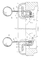
- a spraying-angle selector 6 is provided to substitute the aforementioned hollow ball 53 in accordance with the present invention.
- the selector 6 comprises a rotating knob 61, a stepwise driving element 62, a driving bellows 63, a restoring spring 64, an upper plate 65, a lower plate 66 and several connecting rods 67.
- the rotating knob 61 is a hollow cylinder with enclosed top cover and movably mounted in a central hole 651 of the upper plate 65.
- the knob 61 includes a bottom flange 611, two longitudinal keys 612 symmetrically formed inside the cylindrical wall of the knob and each key having a lower tapered end (not shown), and an indicating mark 613 formed on the top surface of the knob to operatively point the arabic numerals 1 - 9 of the scale 652 printed on the plate 65 so as to indicate the selected specific angle of water spray.
- numeral "1" means a lower (minimum) degrees and "9” means a higher (maximum) degrees.
- the stepwise driving element 62 is formed as a cylinder movably jacketed within the knob 61 and formed with a set of rightward-inclined teeth 621 and a set of leftward-inclined teeth 622, respectively formed on two helical slope- surfaces which are equally divided along the perimeter of the cylinder of the driving element 62.
- a disk portion 623 is formed on the bottom portion of the element 62 to fix the upper end of the driving bellows 63. Either set of teeth 621 or 622 is operatively engaged with the lower tapered end of each longitudinal key 612.
- the driving bellows 63 is inserted with a restoring spring 64 inside the bellows 63 and the lower end of the bellows 63 is fixed into a socket 661 of the lower plate 66 which is installed on the toilet seat or a frame (not shown) near the toilet and is combined with the upper plate 65 by several connecting rods 67 linked between the two plates 65, 66.
- a bottom hole 662 is formed on the plate 66 to fluidically connect the tube 52 directing the fluid in the driving bellows 63 towards the follower bellows 51 of the spraying- angle adjuster 5.
- the nozzle 3 having a fixed spraying angle 8 with water-spray direction L1 can be biased for changing its spraying direction when rotating the knob clockwise (direction RI) from original numeral "1" towards numeral "2", for instance, the longitudinal keys 612 will rotationally drive the two sets of teeth 621, 622 to descend the driving element 62 to press the driving bellows 63 so as to compress the internal fluid to expand the lower follower bellows 51 to bias the nozzle 3 in a direction R2 and to variate the spray direction clockwise (R3) from L1 to L2 as shown in dotted line of Figure 7.
- the longitudinal keys 612 will rotationally drive the two sets of teeth 621, 622 to descend the driving element 62 to press the driving bellows 63 so as to compress the internal fluid to expand the lower follower bellows 51 to bias the nozzle 3 in a direction R2 and to variate the spray direction clockwise (R3) from L1 to L2 as shown in dotted line of Figure 7.
- the knob 61 of this invention can be rotated to selectively obtain a desired optimum spraying angle, which can be specifically set by any user as indicated by any one of arabic numerals 1 - 9 as shown on the upper plate 65 so that the user will quickly and conveniently regain his or her preferable angle in next use, without wasting time to find out the angle through a trial-and-error method.
Landscapes
- Health & Medical Sciences (AREA)
- Public Health (AREA)
- Molecular Biology (AREA)
- Epidemiology (AREA)
- Life Sciences & Earth Sciences (AREA)
- Engineering & Computer Science (AREA)
- Hydrology & Water Resources (AREA)
- Water Supply & Treatment (AREA)
- Bidet-Like Cleaning Device And Other Flush Toilet Accessories (AREA)
- Infusion, Injection, And Reservoir Apparatuses (AREA)
Claims (2)
Priority Applications (1)
| Application Number | Priority Date | Filing Date | Title |
|---|---|---|---|
| AT86307400T ATE42982T1 (de) | 1985-09-25 | 1986-09-25 | Toilette mit verstellbaren wasserduesen. |
Applications Claiming Priority (2)
| Application Number | Priority Date | Filing Date | Title |
|---|---|---|---|
| US779833 | 1985-09-25 | ||
| US06/779,833 US4617688A (en) | 1985-09-25 | 1985-09-25 | Toilet having adjustable water-spray nozzles |
Publications (3)
| Publication Number | Publication Date |
|---|---|
| EP0216641A2 EP0216641A2 (de) | 1987-04-01 |
| EP0216641A3 EP0216641A3 (en) | 1987-06-03 |
| EP0216641B1 true EP0216641B1 (de) | 1989-05-10 |
Family
ID=25117713
Family Applications (1)
| Application Number | Title | Priority Date | Filing Date |
|---|---|---|---|
| EP86307400A Expired EP0216641B1 (de) | 1985-09-25 | 1986-09-25 | Toilette mit verstellbaren Wasserdüsen |
Country Status (8)
| Country | Link |
|---|---|
| US (1) | US4617688A (de) |
| EP (1) | EP0216641B1 (de) |
| AT (1) | ATE42982T1 (de) |
| BR (1) | BR8604461A (de) |
| DE (1) | DE3663275D1 (de) |
| ES (1) | ES2002761A6 (de) |
| PH (1) | PH23159A (de) |
| ZA (1) | ZA867029B (de) |
Families Citing this family (4)
| Publication number | Priority date | Publication date | Assignee | Title |
|---|---|---|---|---|
| JPS6272834A (ja) * | 1985-09-24 | 1987-04-03 | アイシン精機株式会社 | 局部洗浄装置 |
| IT1200355B (it) * | 1986-12-22 | 1989-01-12 | Renzo Taroni | Vaso per water-closet con ciambella dotata di getti di lavaggio per uso intimo |
| US4995121A (en) * | 1989-09-22 | 1991-02-26 | Barker Douglas J | Compact bidet assembly with external adjustment |
| CN113995337A (zh) * | 2021-10-25 | 2022-02-01 | 李维清 | 一种仿生坐便器圈 |
Family Cites Families (8)
| Publication number | Priority date | Publication date | Assignee | Title |
|---|---|---|---|---|
| US2058003A (en) * | 1935-04-11 | 1936-10-20 | Holden H Davies | Colon irrigator |
| US2104271A (en) * | 1937-06-23 | 1938-01-04 | Parisini Primo | Spraying device for evacuation |
| US3015826A (en) * | 1960-02-10 | 1962-01-09 | Tondena Inc | Flush toilet sanitary devices |
| US3916453A (en) * | 1973-06-04 | 1975-11-04 | Dominguez Armada Pedro | Portable bidet |
| US3947899A (en) * | 1974-08-22 | 1976-04-06 | Robinson Joseph D | Warm water supply kit |
| DE3067668D1 (en) * | 1980-02-22 | 1984-06-07 | Peter Butterfield | Hygiene apparatus for toilets |
| DE3042581A1 (de) * | 1980-11-12 | 1982-06-16 | Ideal-Standard Gmbh, 5300 Bonn | Strahlduese mit einem schwenkbaren auslaufmundstueck |
| US4551867A (en) * | 1983-11-04 | 1985-11-12 | Joseph Gurevich | Toilet bowl which washes |
-
1985
- 1985-09-25 US US06/779,833 patent/US4617688A/en not_active Expired - Fee Related
-
1986
- 1986-09-16 ZA ZA867029A patent/ZA867029B/xx unknown
- 1986-09-17 BR BR8604461A patent/BR8604461A/pt unknown
- 1986-09-23 ES ES8602094A patent/ES2002761A6/es not_active Expired
- 1986-09-25 EP EP86307400A patent/EP0216641B1/de not_active Expired
- 1986-09-25 DE DE8686307400T patent/DE3663275D1/de not_active Expired
- 1986-09-25 PH PH34291A patent/PH23159A/en unknown
- 1986-09-25 AT AT86307400T patent/ATE42982T1/de not_active IP Right Cessation
Also Published As
| Publication number | Publication date |
|---|---|
| ZA867029B (en) | 1987-05-27 |
| ATE42982T1 (de) | 1989-05-15 |
| EP0216641A2 (de) | 1987-04-01 |
| DE3663275D1 (en) | 1989-06-15 |
| PH23159A (en) | 1989-05-19 |
| BR8604461A (pt) | 1987-05-19 |
| ES2002761A6 (es) | 1988-10-01 |
| EP0216641A3 (en) | 1987-06-03 |
| US4617688A (en) | 1986-10-21 |
Similar Documents
| Publication | Publication Date | Title |
|---|---|---|
| US5647069A (en) | Adjustable personal hygiene system | |
| US4094018A (en) | Bottom douche for flush toilets | |
| US5911516A (en) | Bidet attachment for toilet bowls | |
| US4334329A (en) | Attachment for a water closet | |
| EP0216641B1 (de) | Toilette mit verstellbaren Wasserdüsen | |
| JP2002525458A (ja) | デュアルフラッシュバルブ | |
| AU704759B2 (en) | A dual flush assembly for water closets | |
| EP0530965A1 (de) | Toilette mit Reinigungswasserzufuhrvorrichtung | |
| US20110094022A1 (en) | Dual flush device for toilet water tank | |
| CN214884161U (zh) | 智能马桶盖和智能马桶 | |
| JPH0152532B2 (de) | ||
| US20020144337A1 (en) | Toilet having odor removing and automatic seat lifting capacity | |
| EP0034673B1 (de) | Hygienische Vorrichtung für Toiletten | |
| US11873632B2 (en) | Urine catcher for a urinal | |
| JPS629412Y2 (de) | ||
| KR102761836B1 (ko) | 비데노즐유닛의 위치조정이 가능한 양변기용 비데 | |
| KR200218920Y1 (ko) | 좌변기 비데장치 | |
| JPH09203103A (ja) | 局部洗浄装置付き便座装置 | |
| KR950001775Y1 (ko) | 온수세정장치의 노즐위치 제어구조 | |
| WO1995000721A1 (en) | Sanitary spray arrangement for toilet bowl | |
| KR200320401Y1 (ko) | 각도가 조절되는 원적외선 램프를 갖는 양변기용 좌대 | |
| JPS59102031A (ja) | 衛生洗浄装置 | |
| JPH025463U (de) | ||
| KR950001778Y1 (ko) | 온수세정장치의 조작레버 복귀구조 | |
| JPH0139812Y2 (de) |
Legal Events
| Date | Code | Title | Description |
|---|---|---|---|
| PUAI | Public reference made under article 153(3) epc to a published international application that has entered the european phase |
Free format text: ORIGINAL CODE: 0009012 |
|
| AK | Designated contracting states |
Kind code of ref document: A2 Designated state(s): AT BE CH DE FR GB IT LI LU NL SE |
|
| PUAL | Search report despatched |
Free format text: ORIGINAL CODE: 0009013 |
|
| AK | Designated contracting states |
Kind code of ref document: A3 Designated state(s): AT BE CH DE FR GB IT LI LU NL SE |
|
| 17P | Request for examination filed |
Effective date: 19871124 |
|
| 17Q | First examination report despatched |
Effective date: 19881007 |
|
| GRAA | (expected) grant |
Free format text: ORIGINAL CODE: 0009210 |
|
| AK | Designated contracting states |
Kind code of ref document: B1 Designated state(s): AT BE CH DE FR GB IT LI LU NL SE |
|
| PG25 | Lapsed in a contracting state [announced via postgrant information from national office to epo] |
Ref country code: NL Effective date: 19890510 Ref country code: BE Effective date: 19890510 Ref country code: CH Effective date: 19890510 Ref country code: SE Effective date: 19890510 Ref country code: AT Effective date: 19890510 Ref country code: LI Effective date: 19890510 Ref country code: FR Free format text: THE PATENT HAS BEEN ANNULLED BY A DECISION OF A NATIONAL AUTHORITY Effective date: 19890510 Ref country code: IT Free format text: LAPSE BECAUSE OF FAILURE TO SUBMIT A TRANSLATION OF THE DESCRIPTION OR TO PAY THE FEE WITHIN THE PRE;WARNING: LAPSES OF ITALIAN PATENTS WITH EFFECTIVE DATE BEFORE 2007 MAY HAVE OCCURRED AT ANY TIME BEFORE 2007. THE CORRECT EFFECTIVE DATE MAY BE DIFFERENT FROM THE ONE RECORDED.SCRIBED TIME-LIMIT Effective date: 19890510 |
|
| REF | Corresponds to: |
Ref document number: 42982 Country of ref document: AT Date of ref document: 19890515 Kind code of ref document: T |
|
| REF | Corresponds to: |
Ref document number: 3663275 Country of ref document: DE Date of ref document: 19890615 |
|
| REG | Reference to a national code |
Ref country code: CH Ref legal event code: PL |
|
| EN | Fr: translation not filed | ||
| PG25 | Lapsed in a contracting state [announced via postgrant information from national office to epo] |
Ref country code: LU Free format text: LAPSE BECAUSE OF NON-PAYMENT OF DUE FEES Effective date: 19890930 |
|
| NLV1 | Nl: lapsed or annulled due to failure to fulfill the requirements of art. 29p and 29m of the patents act | ||
| PLBE | No opposition filed within time limit |
Free format text: ORIGINAL CODE: 0009261 |
|
| STAA | Information on the status of an ep patent application or granted ep patent |
Free format text: STATUS: NO OPPOSITION FILED WITHIN TIME LIMIT |
|
| 26N | No opposition filed | ||
| PG25 | Lapsed in a contracting state [announced via postgrant information from national office to epo] |
Ref country code: DE Effective date: 19900601 |
|
| PG25 | Lapsed in a contracting state [announced via postgrant information from national office to epo] |
Ref country code: GB Effective date: 19900925 |
|
| GBPC | Gb: european patent ceased through non-payment of renewal fee |