EP0216576B1 - Fehlerdetektoreinrichtung für Rohrschweissverbindungen - Google Patents
Fehlerdetektoreinrichtung für Rohrschweissverbindungen Download PDFInfo
- Publication number
- EP0216576B1 EP0216576B1 EP19860307010 EP86307010A EP0216576B1 EP 0216576 B1 EP0216576 B1 EP 0216576B1 EP 19860307010 EP19860307010 EP 19860307010 EP 86307010 A EP86307010 A EP 86307010A EP 0216576 B1 EP0216576 B1 EP 0216576B1
- Authority
- EP
- European Patent Office
- Prior art keywords
- signal
- current
- welding
- output
- fault
- Prior art date
- Legal status (The legal status is an assumption and is not a legal conclusion. Google has not performed a legal analysis and makes no representation as to the accuracy of the status listed.)
- Expired - Lifetime
Links
Images

Classifications
-
- B—PERFORMING OPERATIONS; TRANSPORTING
- B29—WORKING OF PLASTICS; WORKING OF SUBSTANCES IN A PLASTIC STATE IN GENERAL
- B29C—SHAPING OR JOINING OF PLASTICS; SHAPING OF MATERIAL IN A PLASTIC STATE, NOT OTHERWISE PROVIDED FOR; AFTER-TREATMENT OF THE SHAPED PRODUCTS, e.g. REPAIRING
- B29C65/00—Joining or sealing of preformed parts, e.g. welding of plastics materials; Apparatus therefor
- B29C65/02—Joining or sealing of preformed parts, e.g. welding of plastics materials; Apparatus therefor by heating, with or without pressure
- B29C65/34—Joining or sealing of preformed parts, e.g. welding of plastics materials; Apparatus therefor by heating, with or without pressure using heated elements which remain in the joint, e.g. "verlorenes Schweisselement"
- B29C65/3404—Joining or sealing of preformed parts, e.g. welding of plastics materials; Apparatus therefor by heating, with or without pressure using heated elements which remain in the joint, e.g. "verlorenes Schweisselement" characterised by the type of heated elements which remain in the joint
- B29C65/342—Joining or sealing of preformed parts, e.g. welding of plastics materials; Apparatus therefor by heating, with or without pressure using heated elements which remain in the joint, e.g. "verlorenes Schweisselement" characterised by the type of heated elements which remain in the joint comprising at least a single wire, e.g. in the form of a winding
-
- B—PERFORMING OPERATIONS; TRANSPORTING
- B29—WORKING OF PLASTICS; WORKING OF SUBSTANCES IN A PLASTIC STATE IN GENERAL
- B29C—SHAPING OR JOINING OF PLASTICS; SHAPING OF MATERIAL IN A PLASTIC STATE, NOT OTHERWISE PROVIDED FOR; AFTER-TREATMENT OF THE SHAPED PRODUCTS, e.g. REPAIRING
- B29C66/00—General aspects of processes or apparatus for joining preformed parts
- B29C66/01—General aspects dealing with the joint area or with the area to be joined
- B29C66/05—Particular design of joint configurations
- B29C66/10—Particular design of joint configurations particular design of the joint cross-sections
- B29C66/11—Joint cross-sections comprising a single joint-segment, i.e. one of the parts to be joined comprising a single joint-segment in the joint cross-section
- B29C66/112—Single lapped joints
- B29C66/1122—Single lap to lap joints, i.e. overlap joints
-
- B—PERFORMING OPERATIONS; TRANSPORTING
- B29—WORKING OF PLASTICS; WORKING OF SUBSTANCES IN A PLASTIC STATE IN GENERAL
- B29C—SHAPING OR JOINING OF PLASTICS; SHAPING OF MATERIAL IN A PLASTIC STATE, NOT OTHERWISE PROVIDED FOR; AFTER-TREATMENT OF THE SHAPED PRODUCTS, e.g. REPAIRING
- B29C66/00—General aspects of processes or apparatus for joining preformed parts
- B29C66/50—General aspects of joining tubular articles; General aspects of joining long products, i.e. bars or profiled elements; General aspects of joining single elements to tubular articles, hollow articles or bars; General aspects of joining several hollow-preforms to form hollow or tubular articles
- B29C66/51—Joining tubular articles, profiled elements or bars; Joining single elements to tubular articles, hollow articles or bars; Joining several hollow-preforms to form hollow or tubular articles
- B29C66/52—Joining tubular articles, bars or profiled elements
- B29C66/522—Joining tubular articles
- B29C66/5221—Joining tubular articles for forming coaxial connections, i.e. the tubular articles to be joined forming a zero angle relative to each other
-
- B—PERFORMING OPERATIONS; TRANSPORTING
- B29—WORKING OF PLASTICS; WORKING OF SUBSTANCES IN A PLASTIC STATE IN GENERAL
- B29C—SHAPING OR JOINING OF PLASTICS; SHAPING OF MATERIAL IN A PLASTIC STATE, NOT OTHERWISE PROVIDED FOR; AFTER-TREATMENT OF THE SHAPED PRODUCTS, e.g. REPAIRING
- B29C66/00—General aspects of processes or apparatus for joining preformed parts
- B29C66/50—General aspects of joining tubular articles; General aspects of joining long products, i.e. bars or profiled elements; General aspects of joining single elements to tubular articles, hollow articles or bars; General aspects of joining several hollow-preforms to form hollow or tubular articles
- B29C66/51—Joining tubular articles, profiled elements or bars; Joining single elements to tubular articles, hollow articles or bars; Joining several hollow-preforms to form hollow or tubular articles
- B29C66/52—Joining tubular articles, bars or profiled elements
- B29C66/522—Joining tubular articles
- B29C66/5229—Joining tubular articles involving the use of a socket
-
- B—PERFORMING OPERATIONS; TRANSPORTING
- B29—WORKING OF PLASTICS; WORKING OF SUBSTANCES IN A PLASTIC STATE IN GENERAL
- B29C—SHAPING OR JOINING OF PLASTICS; SHAPING OF MATERIAL IN A PLASTIC STATE, NOT OTHERWISE PROVIDED FOR; AFTER-TREATMENT OF THE SHAPED PRODUCTS, e.g. REPAIRING
- B29C66/00—General aspects of processes or apparatus for joining preformed parts
- B29C66/70—General aspects of processes or apparatus for joining preformed parts characterised by the composition, physical properties or the structure of the material of the parts to be joined; Joining with non-plastics material
- B29C66/73—General aspects of processes or apparatus for joining preformed parts characterised by the composition, physical properties or the structure of the material of the parts to be joined; Joining with non-plastics material characterised by the intensive physical properties of the material of the parts to be joined, by the optical properties of the material of the parts to be joined, by the extensive physical properties of the parts to be joined, by the state of the material of the parts to be joined or by the material of the parts to be joined being a thermoplastic or a thermoset
- B29C66/739—General aspects of processes or apparatus for joining preformed parts characterised by the composition, physical properties or the structure of the material of the parts to be joined; Joining with non-plastics material characterised by the intensive physical properties of the material of the parts to be joined, by the optical properties of the material of the parts to be joined, by the extensive physical properties of the parts to be joined, by the state of the material of the parts to be joined or by the material of the parts to be joined being a thermoplastic or a thermoset characterised by the material of the parts to be joined being a thermoplastic or a thermoset
- B29C66/7392—General aspects of processes or apparatus for joining preformed parts characterised by the composition, physical properties or the structure of the material of the parts to be joined; Joining with non-plastics material characterised by the intensive physical properties of the material of the parts to be joined, by the optical properties of the material of the parts to be joined, by the extensive physical properties of the parts to be joined, by the state of the material of the parts to be joined or by the material of the parts to be joined being a thermoplastic or a thermoset characterised by the material of the parts to be joined being a thermoplastic or a thermoset characterised by the material of at least one of the parts being a thermoplastic
- B29C66/73921—General aspects of processes or apparatus for joining preformed parts characterised by the composition, physical properties or the structure of the material of the parts to be joined; Joining with non-plastics material characterised by the intensive physical properties of the material of the parts to be joined, by the optical properties of the material of the parts to be joined, by the extensive physical properties of the parts to be joined, by the state of the material of the parts to be joined or by the material of the parts to be joined being a thermoplastic or a thermoset characterised by the material of the parts to be joined being a thermoplastic or a thermoset characterised by the material of at least one of the parts being a thermoplastic characterised by the materials of both parts being thermoplastics
-
- B—PERFORMING OPERATIONS; TRANSPORTING
- B29—WORKING OF PLASTICS; WORKING OF SUBSTANCES IN A PLASTIC STATE IN GENERAL
- B29C—SHAPING OR JOINING OF PLASTICS; SHAPING OF MATERIAL IN A PLASTIC STATE, NOT OTHERWISE PROVIDED FOR; AFTER-TREATMENT OF THE SHAPED PRODUCTS, e.g. REPAIRING
- B29C66/00—General aspects of processes or apparatus for joining preformed parts
- B29C66/90—Measuring or controlling the joining process
- B29C66/91—Measuring or controlling the joining process by measuring or controlling the temperature, the heat or the thermal flux
- B29C66/912—Measuring or controlling the joining process by measuring or controlling the temperature, the heat or the thermal flux by measuring the temperature, the heat or the thermal flux
- B29C66/9131—Measuring or controlling the joining process by measuring or controlling the temperature, the heat or the thermal flux by measuring the temperature, the heat or the thermal flux by measuring the heat or the thermal flux, i.e. the heat flux
- B29C66/91311—Measuring or controlling the joining process by measuring or controlling the temperature, the heat or the thermal flux by measuring the temperature, the heat or the thermal flux by measuring the heat or the thermal flux, i.e. the heat flux by measuring the heat generated by Joule heating or induction heating
- B29C66/91315—Measuring or controlling the joining process by measuring or controlling the temperature, the heat or the thermal flux by measuring the temperature, the heat or the thermal flux by measuring the heat or the thermal flux, i.e. the heat flux by measuring the heat generated by Joule heating or induction heating by measuring the current intensity
-
- B—PERFORMING OPERATIONS; TRANSPORTING
- B29—WORKING OF PLASTICS; WORKING OF SUBSTANCES IN A PLASTIC STATE IN GENERAL
- B29C—SHAPING OR JOINING OF PLASTICS; SHAPING OF MATERIAL IN A PLASTIC STATE, NOT OTHERWISE PROVIDED FOR; AFTER-TREATMENT OF THE SHAPED PRODUCTS, e.g. REPAIRING
- B29C66/00—General aspects of processes or apparatus for joining preformed parts
- B29C66/90—Measuring or controlling the joining process
- B29C66/91—Measuring or controlling the joining process by measuring or controlling the temperature, the heat or the thermal flux
- B29C66/914—Measuring or controlling the joining process by measuring or controlling the temperature, the heat or the thermal flux by controlling or regulating the temperature, the heat or the thermal flux
- B29C66/9161—Measuring or controlling the joining process by measuring or controlling the temperature, the heat or the thermal flux by controlling or regulating the temperature, the heat or the thermal flux by controlling or regulating the heat or the thermal flux, i.e. the heat flux
- B29C66/91641—Measuring or controlling the joining process by measuring or controlling the temperature, the heat or the thermal flux by controlling or regulating the temperature, the heat or the thermal flux by controlling or regulating the heat or the thermal flux, i.e. the heat flux the heat or the thermal flux being non-constant over time
- B29C66/91643—Measuring or controlling the joining process by measuring or controlling the temperature, the heat or the thermal flux by controlling or regulating the temperature, the heat or the thermal flux by controlling or regulating the heat or the thermal flux, i.e. the heat flux the heat or the thermal flux being non-constant over time following a heat-time profile
-
- B—PERFORMING OPERATIONS; TRANSPORTING
- B29—WORKING OF PLASTICS; WORKING OF SUBSTANCES IN A PLASTIC STATE IN GENERAL
- B29C—SHAPING OR JOINING OF PLASTICS; SHAPING OF MATERIAL IN A PLASTIC STATE, NOT OTHERWISE PROVIDED FOR; AFTER-TREATMENT OF THE SHAPED PRODUCTS, e.g. REPAIRING
- B29C66/00—General aspects of processes or apparatus for joining preformed parts
- B29C66/90—Measuring or controlling the joining process
- B29C66/91—Measuring or controlling the joining process by measuring or controlling the temperature, the heat or the thermal flux
- B29C66/914—Measuring or controlling the joining process by measuring or controlling the temperature, the heat or the thermal flux by controlling or regulating the temperature, the heat or the thermal flux
- B29C66/9161—Measuring or controlling the joining process by measuring or controlling the temperature, the heat or the thermal flux by controlling or regulating the temperature, the heat or the thermal flux by controlling or regulating the heat or the thermal flux, i.e. the heat flux
- B29C66/91651—Measuring or controlling the joining process by measuring or controlling the temperature, the heat or the thermal flux by controlling or regulating the temperature, the heat or the thermal flux by controlling or regulating the heat or the thermal flux, i.e. the heat flux by controlling or regulating the heat generated by Joule heating or induction heating
- B29C66/91655—Measuring or controlling the joining process by measuring or controlling the temperature, the heat or the thermal flux by controlling or regulating the temperature, the heat or the thermal flux by controlling or regulating the heat or the thermal flux, i.e. the heat flux by controlling or regulating the heat generated by Joule heating or induction heating by controlling or regulating the current intensity
-
- B—PERFORMING OPERATIONS; TRANSPORTING
- B29—WORKING OF PLASTICS; WORKING OF SUBSTANCES IN A PLASTIC STATE IN GENERAL
- B29C—SHAPING OR JOINING OF PLASTICS; SHAPING OF MATERIAL IN A PLASTIC STATE, NOT OTHERWISE PROVIDED FOR; AFTER-TREATMENT OF THE SHAPED PRODUCTS, e.g. REPAIRING
- B29C66/00—General aspects of processes or apparatus for joining preformed parts
- B29C66/90—Measuring or controlling the joining process
- B29C66/96—Measuring or controlling the joining process characterised by the method for implementing the controlling of the joining process
- B29C66/961—Measuring or controlling the joining process characterised by the method for implementing the controlling of the joining process involving a feedback loop mechanism, e.g. comparison with a desired value
-
- H—ELECTRICITY
- H02—GENERATION; CONVERSION OR DISTRIBUTION OF ELECTRIC POWER
- H02H—EMERGENCY PROTECTIVE CIRCUIT ARRANGEMENTS
- H02H3/00—Emergency protective circuit arrangements for automatic disconnection directly responsive to an undesired change from normal electric working condition with or without subsequent reconnection ; integrated protection
- H02H3/08—Emergency protective circuit arrangements for automatic disconnection directly responsive to an undesired change from normal electric working condition with or without subsequent reconnection ; integrated protection responsive to excess current
- H02H3/093—Emergency protective circuit arrangements for automatic disconnection directly responsive to an undesired change from normal electric working condition with or without subsequent reconnection ; integrated protection responsive to excess current with timing means
-
- B—PERFORMING OPERATIONS; TRANSPORTING
- B29—WORKING OF PLASTICS; WORKING OF SUBSTANCES IN A PLASTIC STATE IN GENERAL
- B29C—SHAPING OR JOINING OF PLASTICS; SHAPING OF MATERIAL IN A PLASTIC STATE, NOT OTHERWISE PROVIDED FOR; AFTER-TREATMENT OF THE SHAPED PRODUCTS, e.g. REPAIRING
- B29C65/00—Joining or sealing of preformed parts, e.g. welding of plastics materials; Apparatus therefor
- B29C65/02—Joining or sealing of preformed parts, e.g. welding of plastics materials; Apparatus therefor by heating, with or without pressure
- B29C65/34—Joining or sealing of preformed parts, e.g. welding of plastics materials; Apparatus therefor by heating, with or without pressure using heated elements which remain in the joint, e.g. "verlorenes Schweisselement"
- B29C65/3472—Joining or sealing of preformed parts, e.g. welding of plastics materials; Apparatus therefor by heating, with or without pressure using heated elements which remain in the joint, e.g. "verlorenes Schweisselement" characterised by the composition of the heated elements which remain in the joint
- B29C65/3476—Joining or sealing of preformed parts, e.g. welding of plastics materials; Apparatus therefor by heating, with or without pressure using heated elements which remain in the joint, e.g. "verlorenes Schweisselement" characterised by the composition of the heated elements which remain in the joint being metallic
-
- B—PERFORMING OPERATIONS; TRANSPORTING
- B29—WORKING OF PLASTICS; WORKING OF SUBSTANCES IN A PLASTIC STATE IN GENERAL
- B29C—SHAPING OR JOINING OF PLASTICS; SHAPING OF MATERIAL IN A PLASTIC STATE, NOT OTHERWISE PROVIDED FOR; AFTER-TREATMENT OF THE SHAPED PRODUCTS, e.g. REPAIRING
- B29C66/00—General aspects of processes or apparatus for joining preformed parts
- B29C66/70—General aspects of processes or apparatus for joining preformed parts characterised by the composition, physical properties or the structure of the material of the parts to be joined; Joining with non-plastics material
- B29C66/71—General aspects of processes or apparatus for joining preformed parts characterised by the composition, physical properties or the structure of the material of the parts to be joined; Joining with non-plastics material characterised by the composition of the plastics material of the parts to be joined
-
- B—PERFORMING OPERATIONS; TRANSPORTING
- B29—WORKING OF PLASTICS; WORKING OF SUBSTANCES IN A PLASTIC STATE IN GENERAL
- B29C—SHAPING OR JOINING OF PLASTICS; SHAPING OF MATERIAL IN A PLASTIC STATE, NOT OTHERWISE PROVIDED FOR; AFTER-TREATMENT OF THE SHAPED PRODUCTS, e.g. REPAIRING
- B29C66/00—General aspects of processes or apparatus for joining preformed parts
- B29C66/90—Measuring or controlling the joining process
- B29C66/94—Measuring or controlling the joining process by measuring or controlling the time
- B29C66/944—Measuring or controlling the joining process by measuring or controlling the time by controlling or regulating the time
-
- B—PERFORMING OPERATIONS; TRANSPORTING
- B29—WORKING OF PLASTICS; WORKING OF SUBSTANCES IN A PLASTIC STATE IN GENERAL
- B29C—SHAPING OR JOINING OF PLASTICS; SHAPING OF MATERIAL IN A PLASTIC STATE, NOT OTHERWISE PROVIDED FOR; AFTER-TREATMENT OF THE SHAPED PRODUCTS, e.g. REPAIRING
- B29C66/00—General aspects of processes or apparatus for joining preformed parts
- B29C66/90—Measuring or controlling the joining process
- B29C66/94—Measuring or controlling the joining process by measuring or controlling the time
- B29C66/949—Measuring or controlling the joining process by measuring or controlling the time characterised by specific time values or ranges
-
- B—PERFORMING OPERATIONS; TRANSPORTING
- B29—WORKING OF PLASTICS; WORKING OF SUBSTANCES IN A PLASTIC STATE IN GENERAL
- B29C—SHAPING OR JOINING OF PLASTICS; SHAPING OF MATERIAL IN A PLASTIC STATE, NOT OTHERWISE PROVIDED FOR; AFTER-TREATMENT OF THE SHAPED PRODUCTS, e.g. REPAIRING
- B29C66/00—General aspects of processes or apparatus for joining preformed parts
- B29C66/90—Measuring or controlling the joining process
- B29C66/95—Measuring or controlling the joining process by measuring or controlling specific variables not covered by groups B29C66/91 - B29C66/94
- B29C66/959—Measuring or controlling the joining process by measuring or controlling specific variables not covered by groups B29C66/91 - B29C66/94 characterised by specific values or ranges of said specific variables
- B29C66/9592—Measuring or controlling the joining process by measuring or controlling specific variables not covered by groups B29C66/91 - B29C66/94 characterised by specific values or ranges of said specific variables in explicit relation to another variable, e.g. X-Y diagrams
Definitions
- This invention relates to a method of and a device for detecting a fault when making welded joints in thermoplastic pipe using so-called electro-fusion fittings.
- An electro-fusion fitting generally comprises a body of thermoplastic material having an electrical resistance heating element disposed adjacent a surface of the body and to which an electric current may be supplied to fuse the material of the body to that of a pipe.
- the fittings are frequently used in the production of joints between lengths of thermoplastic pipe, such as polyethylene pipe which is used in the gas industry.
- a fitting for joining two pipes end-to-end usually comprises a sleeve or muff incorporating a coil of resistance heating wire adjacent its inner surface. The ends of the pipes to be connected are pushed into the sleeve, the heating coil is connected to a suitable power supply and an electric current is supplied to the coil for a controlled period to soften and fuse the material of the fitting and pipes so that they become firmly welded together.
- Pipe joints obtained by use of electro-fusion fittings are generally satisfactory, but the weld strength achieved depends upon the correct level of electric current being supplied for the correct amount of time, and these factors differ for fittings of different sizes and types.
- EP-A-0076043 there is described a control system which sets automatically the correct time for which current is supplied to a fitting, whereby the manufacture of satisfactory joints is simplified.
- the standard of joint obtained is also dependent upon the pipes and sleeve being correctly assembled together before delivering the current to the heating coil.
- a faulty joint can result and may not be detectable by visual inspection of the completed joint.
- the pipes and sleeve are correctly assembled the flow of molten material is small during the welding process, but if they are not properly assembled the flow can be fairly substantial leading to adjacent turns of the heating coil becoming pushed together and shorting. As a consequence over-heating may occur and in extreme cases the current may rise to such a level that the wire may melt and break, possibly causing a spark which can be highly dangerous if gas is present.
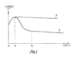
- the present invention is based on the realisation that an unexpected rise in the electric current flowing in the heating coil is indicative of improper conditions during the welding process.
- a method of detecting a fault in an electro-fusion welding process comprising the steps of sensing the welding current flowing through an electro-fusion fitting and generating a signal dependent upon the current sensed, monitoring said current dependent signal and producing a fault indicative output signal in response to a change in the current dependent signal due to an increase in the welding current, after a short initial welding period during which the welding current should reach a maximum for the welding process.
- the output signal can be relied upon e.g. to actuate an alarm and/or to interrupt the current supply to the fitting, if the current level rises unexpectedly during the welding process.
- the invention provides a device for detecting a fault during an electro-fusion welding process, comprising means for sensing the welding current flowing through an electro-fusion fitting and producing a signal dependent the current sensed, and means coupled to receive the current dependent signal for monitoring said signal and producing a fault indicative output signal if, after a short initial period during which the welding current should reach a maximum, the current dependent signal changes in accordance with the welding current having increased.
- the current dependent signal is compared with a reference signal.
- the means coupled to the sensing means is arranged to sample and hold the current level at a first time t1, and to sample the current level at subsequent intervals and compare the current level with the reference level taken at time t1. It is expedient for the reference current level to be taken when the current should have reached a relatively stable condition after an initial period.
- the illustrated embodiment of the invention includes a current transformer 1 for sensing the electric current 1 being supplied to an electro-fusion fitting 20 from control equipment 30 which may be as described in the above mentioned European patent specification EP-A-0076043.
- the output from the transformer 1, e.g. about 10 volts for maximum current of, say, 50 amps to the fitting 20, is fed to an RMS to DC converter 2 which provides an output signal proportional to the fitting current, e.g. a nominal 1.5 volts at 50 amps fitting current.
- the RMS current is a direct measure of heat input and has the advantage of being unaffected by the input voltage to the system, waveform distortion and other external influences.
- the converter 2 is connected to an analogue to digital converter 3 which has a control input connected to a control unit 4.
- the converter 3 takes the signal from converter 2 and emits a corresponding output in digital form, such as an eight bit code.
- the unit 4 provides a regular train of control pulses to the converter 3, e.g. at a rate of 1 per second.
- the digital output of the converter 3 is supplied to a first digital to analogue converter 5 and a second digital to analogue converter 6.
- the first converter 5 also has a control input connected to the control unit and on receipt of a control pulse at this input emits an output corresponding to the digital input signal from the converter 3, this output being held until the next control pulse is received from the control unit.
- the second converter 6 produces an output which corresponds to and follows the digital input received from the converter 3.
- the output of converter 5 is connected to a first (-) input of a comparator 7, and the output of converter 6 is connected to the second (+) input of the comparator 7, through a variable resistance 8.
- the comparator 7 produces an output signal only when the signal at the (+) input exceeds that at the (-) input.
- the variable resistor 8 is set so that the signals received at the respective inputs of the comparator 7 are the same when the output from converter 6 is a given percentage, e.g. 10%, greater than that emitted by converter 5.
- the output of the comparator 7 is fed to a second comparator 9 through a delay arrangement.
- the first (-) input of comparator 9 is supplied with a constant signal set by a potential divider.
- the delay arrangement comprises a resistor 10 and a capacitor 11 connected in series between the output of the comparator 7 and ground, the common point between the resistor and capacitor being connected to the second input (+) input of the comparator 9, and a diode 12 being connected in parallel with the resistor.
- An output from the comparator 7 charges the capacitor, the value of which is selected so that the output must be present for at least a given time, preferably about 4 seconds, before the signal received at the (+) input of the comparator 9 exceeds that received at the (-) input so that this comparator also produces an output. If the output from comparator 7 ceases before the given delay period has elapsed, the capacitor 11 discharges through the diode 12 and no signal is emitted from comparator 9.
- the signal from comparator 9 is delivered through a gate 14 controlled by the control unit 4 and may be used to actuate audible and/ or visual alarms or to interrupt the welding process by cutting off the delivery of current to the fitting 20.
- the control unit is arranged so that initially, at t o , the gate 14 is open. At time t 1 , e.g. a delay of 10 secs from t o , the gate 14 is closed and a control pulse is emitted to the converter 5 so that it will produce an output corresponding to the fitting current at that time. It will be appreciated that t1 is chosen so that it exceeds the maximum current time tx for all fittings with which the device is to be used.
- the instantaneous current through the fitting 20 is sensed each second in accordance with the train of control pulses to converter 3 and if the current falls, as is to be expected from the curves shown in figure 1, the output from converter 6 never reaches a level sufficient to switch the comparator 7. Thus, no fault signal is emitted.
- the inclusion of the gate 14 avoids and spurious fault signal being generated before the time t1 has been reached.
- the relatively stable current condition for large fittings need not be reached for a time t y of about 30 secs (which is greater than the welding period for small fittings). So that the reference current sampled and held by the converter 5 is not set too high, which would mean the device might not respond to a subsequent rise in current after t y , a second control pulse is emitted to the converter 5 at t2 which is for example 20 seconds after t1. Thus, converter 5 then resamples and holds the current level at t 2 which is around t y for large fittings and the device will respond to increases in current above this new, lower reference current.
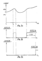
- Figure 3a shows the fitting current rising after time t1 and then falling below the current at t1 before rising again.
- the converter 5 holds the current level at time t1.
- the current has risen above the t1 level by 10%, whereby the comparator 7 switches and starts to charge the capacitor 11.
- the comparator 7 is turned off and the capacitor discharges through the diode 12.
- the output from the comparator 7 is shown in Figure 3b.
- the current again exceeds the trigger level and the comparator 7 switches on and once more starts to charge up the capacitor 11.
- the comparator 9 switches on and emits a fault signal which is used to generate an alarm and or to interrupt the current supply to the fitting 20.
- the output from comparator 9 is shown in Figure 3c.
- a modified fault detecting device embodying the invention the components 5-14 of the device shown in Figure 2 are omitted and the output from the convertor 3 is fed to a microprocessor control unit which replaces the control unit 4, and which includes a memory for storing the sampled current dependent signal, and a counter.
- the welding current dependent signal is sampled at given time intervals, e.g. once every second, and is compared with a reference signal which is the immediately preceding sampled current dependent signal stored in the memory. If the sampled signal exceeds the reference signal a pulse is produced to increase the count of the counter by one, and if the sampled signal is less than the reference signal a pulse is produced to reduce the count by one.
- the fault indicating output signal is emitted in response to the count of the counter reaching a given number, e.g. 4.
- Typical values for the current dependent signal and the count of the counter for a welding current following the curve of Fig. 3a are given by the following table:
Landscapes
- Engineering & Computer Science (AREA)
- Mechanical Engineering (AREA)
- Physics & Mathematics (AREA)
- Thermal Sciences (AREA)
- Lining Or Joining Of Plastics Or The Like (AREA)
- Investigating Or Analyzing Materials By The Use Of Ultrasonic Waves (AREA)
- Arc Welding Control (AREA)
- Analysing Materials By The Use Of Radiation (AREA)
- Examining Or Testing Airtightness (AREA)
Claims (21)
- Ein Verfahren zum Feststellen einer Störung bei einem Elektrofusionsschweißprozeß, welches die Verfahrensschritte enthält:
Erfassen des Schweißstromes, der durch ein Elektrofusionsansclußstück fließt und Erzeugen eines Signales, das von dem erfaßten Strom, der durch ein Elektrofusionsverbindungsstück fließt und Erzeugen eines Signales, das von dem erfaßten Strom abhängt, Überwachen des stromabhängigen Signales und Erzeugen eines Fehleranzeigeausgangssignales in Reaktion auf eine Änderung des stromabhängigen Signales, infolge eines Anwachsens des schweißstromes, nach einer kurzen anfänglichen Schweißperiode, während welcher der Schweißstrom ein Maximum für den Schweißprozeß erreichen sollte. - Ein verfahren nach Anspruch 1,
wobei das stromabhängige Signal mit einem eingestellten Referenzsignal verglichen wird, das einem stromabhängigen Signal entspricht, das repräsentativ für einen Schweißstrom ist, der höher als nach der anfänglichen Periode erwartet ist, und wobei das Ausgangssignal erzeugt wird, wenn das stromabhängige Signal größer als das Referenzsignal wird. - Ein Verfahren nach Anspruch 2,
wobei das Referenzsignal eingestellt wird, um dem stromabhängigen Signal am Ende der anfänglichen Periode zu entsprechen. - Ein Verfahren nach Anspruch 3,
worin während des schweißprozesses das Referenzsignal neu eingestellt wird, um mit dem stromabhängigen Signal nach einer weiteren Zeitperiode, die der anfänglichen Zeitperiode folgt und von längerer Dauer als diese ist, Übereinzustimmen. - Ein Verfahren nach wenigstens einem der Ansprüche 1 bis 4,
wobei das Ausgangssignal für eine kurze Zeitperiode verzögert wird, nachdem ein Fehlerzustand erfaßt worden ist, um zu verhindern, daß das Fehleranzeigeausgangssignal ausgegeben wird, wenn der Schweißstrom nach Erhöhung während dieser Verzögerungsperiode wieder abnimmt. - Eine Vorrichtung zum Erfassen einer Störung während eines Elektrofusionsschweißprozesses, mit einer Einrichtung (1, 2) zum Erfassen des Schweißstromes, der durch ein Elektrofusionsanschlußstück (20) fließt und zum Erzeugen eines Signales, das von dem erfaßten Strom abhängt, und einer Einrichtung (3 bis 7), die angeschlossen ist, um das stromabhängige Signal zur Überwachung dieses Signales zu empfangen, und zum Erzeugen eines Fehleranzeigeausgangssignales wenn, nach einer kurzen anfänglichen zeitperiode (t₁), während der der Schweißstrom ein Maximum erreichen soll, sich das stromabhängige Signal in Übereinstimmung damit, daß sich der Schweißstrom erhöht hat, ändert.
- Eine Vorrichtung nach Anspruch 6, wobei die Stromerfassungseinrichtung zum Feststellen des RMS-Stromes vorgesehen ist.
- Eine Vorrichtung nach Anspruch 6 oder 7,
wobei die Stromerfassungseinrichtung eine Umwandlungseinrichtung (2) zum Erzeugen eines Spannungssignales proportional zum Schweißstrom umfaßt. - Eine Vorrichtung nach wenigstens einem der Ansprüche 6 bis 8,
wobei die Signalüberwachungseinrichtung eine Einrichtung (7) umfaßt, die dazu vorgesehen ist, das stromabhängige Signal, das von der Erfassungseinrichtung empfangen wird, mit einem eingestellten Referenzsignal zu vergleichen. - Eine Vorrichtung nach Anspruch 9,
wobei die Überwachungseinrichtung eine Referenzsignaleinrichtung (5) zum Empfangen des stromabhängigen Signales, das durch die Erfassungseinrichtung am Ende der anfänglichen Periode (t₁) erzeugt wird, und zum Erzeugen des Referenzsignales in Übereinstimmung mit dem stromabhängigen Signal enthält. - Eine Vorrichtung nach Anspruch 10,
wobei eine Einrichtung (4) zum Betrieb der Referenzsignaleinrichtung (5) vorgesehen ist, um das Referenzsignal auf einen Wert neu einzustellen, welcher dem stromabhängigen Signal am Ende einer weiteren Zeitperiode entspricht, die auf die anfängliche zeitperiode folgt und von längerer Dauer als diese ist. - Eine Vorrichtung nach Anspruch 9, 10 oder 11,
wobei die Überwachungseinrichtung eine Einrichtung (6) enthält, um das Referenzsignal und das stromabhängige Signal so einzustellen, daß die Vergleichseinrichtung (7) ein Signal abgibt,das eine Störung nur anzeigt, wenn das stromabhängige Signal einen Schweißstrom repräsentiert, der in der Größenordnung von 10 % höher liegt als der Schweißstrom, der durch das Referenzsignal repräsentiert wird. - Eine Vorrichtung nach wenistens einem der Ansprüche 9 bis 12,
wobei die Überwachungseinrichtung eine Abtasteinrichtung (3) enthält, die mit der Erfassungseinrichtung zum Abtasten des stromabhängigen Signales in vorbestimmten Zeitintervallen verbunden ist, und wobei die Vergleichseinrichtung (7) mit ersten Abtastsignal nachfolgende Abtastsignale vergleicht. - Eine Vorrichtung nach Anspruch 13,
wobei die Überwachungseinrichtung eine Steuereinheit (4) enthält und die Abtasteinrichtung einen ersten Konverter (3) umfaßt, der einen Steuereingang aufweist, der angeschlossen ist, um eine Folge von Steuerimpulsen, die durch die Steuereinheit ausgegeben werden, zu empfangen, wobei der Konverter mit der Sensoreinrichtung zum Empfang des stromabhängigen Signales verbunden und dazu vorgesehen ist, an einem Ausgang davon ein Signal auszugeben, das dem stromabhängigen Signal zu der Zeit des Empfanges des unmittelbar vorhergehenden Steuerimpulses entspricht, und die Vergleichseinrichtung einen Komparator (7) mit zwei Eingängen, ein Paar von zweiten Konvertern (5, 6), von denen Jeder einen Eingang, der mit dem Ausgang das ersten Konverters verbunden ist, und einen Ausgang aufweist, der an einen jeweiligen Eingang des Komparators angeschlossen ist, wobei einer (5) von den zweiten Konvertern einen Steuereingang aufweist, der mit der Steuereinheit (4) verbunden und dazu vorgesehen ist, an einem Ausgang davon ein Signal zu erzeugen, das dem Signal enspricht, das an seinem Eingang zur Zeit des Empfanges des unmittelbar vorhergehenden Impulses an dem Steuereingang empfangen wird, und der andere (6) von den zweiten Konvertern an seinem Ausgang ein Signal erzeugt, das demjenigen entspricht, das an seinem Eingang empfangen wird. - Eine Vorrichtung nach wenigstens einem der Ansprüche 6 bis 14,
wobei die Überwachungseinrichtung eine Signalverzögerungseinrichtung (9 bis 12) zum Verzögern des Fehleranzeigeausgangssignales für eine gegebene Zeit und zum Unterdrücken des Signales enthält, wenn der Schweißstrom sich innerhalb der gegebenen Zeit wieder verringert. - Eine Vorrichtung nach wenigstens einem der Ansprüche 6 bis 15,
wobei eine Gattereinrichtung (14) mit der Überwachungseinrichtung zum Blockieren irgendeines Fehleranzeigeausgangssignales, das während der anfänglichen Zeitperiode erzeugt wird, verbunden ist. - Ein Verfahren nach Anspruch 1,
wobei das stromabhängige Signal mit einen Referenzsignal verglichen wird, das dem Stromsignal zu einem früheren Zeitpunkt während des Schweißprozesses entspricht. - Ein Verfahren nach Anspruch 17,
wobei das stromabhängige Signal zu vorbestimmten Zeitintervallen abgetastet wird, und jedes Abtastsignal mit einem Referenzsignal verglichen wird, das dem unmittelbar vorhergehenden abgetasteten Signal entspricht. - Ein Verfahren nach Anspruch 18,
wobei der Zählwert eines Zählers in Reaktion auf ein Abtastsignal, das das Referenzsignal Übersteigt, erhöht wird, und in Reaktion auf ein Abtastsignal, das geringer als das Referenzsignal ist, verringert wird, und das Fehleranzeigeausgangssignal in Reaktion darauf, daß der Zähler einen gegebenen Zählwert erreicht, erzeugt wird. - Eine Vorrichtung nach Anspruch 6, 7 oder 8,
wobei die Signalüberwachungseinrichtung eine Abtasteinrichtung, welche mit der sensoreinrichtung zum Abtasten des stromabhängigen Signales zu vorbestimmten Zeitintervallen verbunden ist, eine Speichereinrichtung zum Speichern eines abgetasteten Signales, eine Vergleichseinrichtung zum Vergleichen eines abgetasteten Signales mit einem vorhergehenden abgetasteten Signal, das in der Speichereinrichtung gespeichert ist, und zum Erzeugen eines Ausgangssignales in Reaktion auf ein Abtastsignal, das das vorhergehende Abtastsignal übersteigt, und eine Einrichtung zum Empfang des Ausgangssignales aus der Vergleichseinrichtung und zum Erzeugen des Fehleranzeigeausgangssignales umfaßt. - Eine Vorrichtung nach Anspruch 20,
wobei die Einrichtung zum Empfang des Ausgangssignales der Vergleichseinrichtung einen Zähler, wobei die Vergleichseinrichtung ein Signal erzeugt, um den Zählwert des Zählers in Reaktion auf ein Abtastsignal, das das vorhergehende Abtastsignal übersteigt, zu erhöhen und den Zählwert des Zählers in Reaktion auf ein Abtastsignal, das geringer als das vorhergehende Abtastsignal ist, zu vermindern, und eine Einrichtung zum Ausgeben des Fehleranzeigeausgangssignales in Reaktion darauf, daß der Zählwert des Zählers ein vorbestimmtes Niveau erreicht, enthält.
Priority Applications (1)
| Application Number | Priority Date | Filing Date | Title |
|---|---|---|---|
| AT86307010T ATE63496T1 (de) | 1985-09-12 | 1986-09-11 | Fehlerdetektoreinrichtung fuer rohrschweissverbindungen. |
Applications Claiming Priority (2)
| Application Number | Priority Date | Filing Date | Title |
|---|---|---|---|
| GB8522633A GB8522633D0 (en) | 1985-09-12 | 1985-09-12 | Fault detecting device |
| GB8522633 | 1985-09-12 |
Publications (3)
| Publication Number | Publication Date |
|---|---|
| EP0216576A2 EP0216576A2 (de) | 1987-04-01 |
| EP0216576A3 EP0216576A3 (en) | 1988-12-14 |
| EP0216576B1 true EP0216576B1 (de) | 1991-05-15 |
Family
ID=10585090
Family Applications (1)
| Application Number | Title | Priority Date | Filing Date |
|---|---|---|---|
| EP19860307010 Expired - Lifetime EP0216576B1 (de) | 1985-09-12 | 1986-09-11 | Fehlerdetektoreinrichtung für Rohrschweissverbindungen |
Country Status (7)
| Country | Link |
|---|---|
| US (1) | US4795877A (de) |
| EP (1) | EP0216576B1 (de) |
| JP (1) | JPH0655441B2 (de) |
| AT (1) | ATE63496T1 (de) |
| DE (1) | DE3679267D1 (de) |
| DK (1) | DK435286D0 (de) |
| GB (1) | GB8522633D0 (de) |
Families Citing this family (15)
| Publication number | Priority date | Publication date | Assignee | Title |
|---|---|---|---|---|
| JPH07121554B2 (ja) * | 1987-11-02 | 1995-12-25 | 三井石油化学工業株式会社 | エレクトロフュージョン継手の融着部の検査方法 |
| DE3810795C2 (de) * | 1988-03-30 | 1994-04-21 | Huerner Gmbh | Elektro-Schweißgerät zum selbsttätigen Schweißen von Heizwendel-Fittingen |
| JPH085135B2 (ja) * | 1989-01-26 | 1996-01-24 | 積水化学工業株式会社 | 電気溶着装置 |
| DE3930378A1 (de) * | 1989-09-12 | 1991-03-21 | Aro | Schweissverfahren und -vorrichtung |
| FR2654978B1 (fr) * | 1989-11-29 | 1992-02-21 | Gaz De France | Piece de raccordement du type a resistance electrique perfectionnee pour la reunion par thermosoudage d'elements en matiere plastique. |
| US5231265A (en) * | 1990-09-28 | 1993-07-27 | Balance Dynamics Corporation | Method and apparatus for the transfer of electrical power to a balancer |
| SG54246A1 (en) * | 1993-12-15 | 1998-11-16 | Tokoshu Kogyo Kabashikigaisha | Electrofusion fastening apparatus |
| GB2294898B (en) * | 1994-09-26 | 1998-03-18 | Toa Kokyu Tugitevarubu Seizo C | A method of automatically controlling the fusion process between thermoplastic articles |
| US5889262A (en) * | 1997-05-15 | 1999-03-30 | Seah Steel Corporation | System for and method of automatically controlling amount of input heat in high-frequency electric resistance welding machine |
| US7155973B2 (en) * | 2003-07-08 | 2007-01-02 | Stephen William Dyer | Method and apparatus for balancing |
| US6426342B2 (en) * | 1999-08-16 | 2002-07-30 | Revaax Pharmaceuticals, Llc | Use of β-lactamase inhibitors as neuroprotectants |
| US6441352B1 (en) | 2000-01-05 | 2002-08-27 | Ef Technologies, Inc. | Apparatus for electrically heat welding thermoplastic fittings and method of using the same |
| US6953917B2 (en) | 2000-04-10 | 2005-10-11 | Chenault David O | System and method for ensuring the qualification of a workman to perform a task having established required standards |
| US20060202471A1 (en) * | 2005-03-07 | 2006-09-14 | Weisbond Bradley K | Electro-fusion joining system for thermoplastic piping systems |
| US9174299B2 (en) * | 2009-05-15 | 2015-11-03 | Ef Technologies, Inc. | Apparatus and method for portable calibration of electrofusion controllers |
Family Cites Families (10)
| Publication number | Priority date | Publication date | Assignee | Title |
|---|---|---|---|---|
| FR1436386A (fr) * | 1964-06-01 | 1966-04-22 | North American Aviation Inc | Suppresseur dynamique de tension |
| US3564204A (en) * | 1966-06-06 | 1971-02-16 | Siemens Ag | Apparatus for controlling the heating current for welding thermoplastic synthetics |
| JPS4857625U (de) * | 1971-11-01 | 1973-07-23 | ||
| US4416713A (en) * | 1980-07-24 | 1983-11-22 | Brooks Ronald H | Method and apparatus for joining abutting edges of sheet material |
| US4421976A (en) * | 1981-08-26 | 1983-12-20 | General Signal Corporation | System for monitoring heater elements of electric furnaces |
| DE3268829D1 (en) * | 1981-09-30 | 1986-03-13 | Fusion Plastics Ltd | Electro-fusion fitting |
| CH653611A5 (de) * | 1981-12-23 | 1986-01-15 | Fischer Ag Georg | Verfahren und geraet zum verschweissen von leitungselementen. |
| JPS59110321A (ja) * | 1982-12-15 | 1984-06-26 | 株式会社日立製作所 | 過電流検出システム |
| CH658426A5 (de) * | 1983-02-04 | 1986-11-14 | Fischer Ag Georg | Verfahren zum verschweissen von leitungselementen aus thermoplastischem material und eine dafuer geeignete einrichtung. |
| US4642155A (en) * | 1985-05-16 | 1987-02-10 | Central Plastics Company | Thermoplastic fitting electric heat welding method and apparatus |
-
1985
- 1985-09-12 GB GB8522633A patent/GB8522633D0/en active Pending
-
1986
- 1986-09-10 US US06/905,500 patent/US4795877A/en not_active Expired - Fee Related
- 1986-09-11 EP EP19860307010 patent/EP0216576B1/de not_active Expired - Lifetime
- 1986-09-11 DK DK435286A patent/DK435286D0/da not_active Application Discontinuation
- 1986-09-11 DE DE8686307010T patent/DE3679267D1/de not_active Expired - Lifetime
- 1986-09-11 AT AT86307010T patent/ATE63496T1/de not_active IP Right Cessation
- 1986-09-12 JP JP61215567A patent/JPH0655441B2/ja not_active Expired - Lifetime
Also Published As
| Publication number | Publication date |
|---|---|
| GB8522633D0 (en) | 1985-10-16 |
| ATE63496T1 (de) | 1991-06-15 |
| EP0216576A2 (de) | 1987-04-01 |
| US4795877A (en) | 1989-01-03 |
| EP0216576A3 (en) | 1988-12-14 |
| JPS62116128A (ja) | 1987-05-27 |
| DE3679267D1 (de) | 1991-06-20 |
| DK435286D0 (da) | 1986-09-11 |
| JPH0655441B2 (ja) | 1994-07-27 |
Similar Documents
| Publication | Publication Date | Title |
|---|---|---|
| EP0216576B1 (de) | Fehlerdetektoreinrichtung für Rohrschweissverbindungen | |
| EP0076043B1 (de) | Elektrisch verschmelzbares Anschlussstück | |
| US5130518A (en) | Electric welding apparatus for automatically welding heating coil fittings | |
| US4520417A (en) | Electrical monitoring systems | |
| AU707400B2 (en) | Ground fault protecting apparatus and method for solar power generation and solar power generation apparatus using the apparatus and method | |
| US4755733A (en) | Battery charging and cycling devices | |
| EP0463860B1 (de) | Mit isolierter Anzeigeeinrichtung versehener Fühler für fehlerhafte Stromkreise | |
| WO1988005222A1 (en) | Battery charger | |
| US4019067A (en) | Conductive probe level control | |
| US4736091A (en) | Integral sensor controller for an electrical heater | |
| JPH03503353A (ja) | 急速圧力上昇回路 | |
| EP0114473B1 (de) | Verfahren und Vorrichtung zum elektrischen Lichtbogenschweissen | |
| EP0615601B1 (de) | Detektionsschaltung für die entladung einer detektorröhre für ultraviolettstrah-lung | |
| JPS6315905B2 (de) | ||
| JP2524666B2 (ja) | 融着異常検知方法 | |
| KR900007580B1 (ko) | 과전류 보호용 계전기 | |
| CN218897173U (zh) | 一种安全检测装置及其安全检测电路 | |
| US4349397A (en) | Method and device for connecting pipe components made of weldable plastic | |
| AU652239B2 (en) | Electrical isolator | |
| JP3018472B2 (ja) | 耐熱破壊測定方法およびその測定装置 | |
| JP2546019B2 (ja) | 停電検出回路 | |
| JPH10243545A (ja) | 負荷駆動装置 | |
| JPH11115061A (ja) | 電気融着装置 | |
| JP2563508B2 (ja) | 電気加熱調理器の沸騰検出装置 | |
| GB2267400A (en) | Monitoring operation of tap changing power transformer |
Legal Events
| Date | Code | Title | Description |
|---|---|---|---|
| PUAI | Public reference made under article 153(3) epc to a published international application that has entered the european phase |
Free format text: ORIGINAL CODE: 0009012 |
|
| AK | Designated contracting states |
Kind code of ref document: A2 Designated state(s): AT BE CH DE FR GB IT LI LU NL SE |
|
| PUAL | Search report despatched |
Free format text: ORIGINAL CODE: 0009013 |
|
| AK | Designated contracting states |
Kind code of ref document: A3 Designated state(s): AT BE CH DE FR GB IT LI LU NL SE |
|
| 17P | Request for examination filed |
Effective date: 19890605 |
|
| 17Q | First examination report despatched |
Effective date: 19900724 |
|
| RAP1 | Party data changed (applicant data changed or rights of an application transferred) |
Owner name: FUSION GROUP PLC |
|
| GRAA | (expected) grant |
Free format text: ORIGINAL CODE: 0009210 |
|
| AK | Designated contracting states |
Kind code of ref document: B1 Designated state(s): AT BE CH DE FR GB IT LI LU NL SE |
|
| PG25 | Lapsed in a contracting state [announced via postgrant information from national office to epo] |
Ref country code: SE Effective date: 19910515 Ref country code: NL Effective date: 19910515 Ref country code: LI Effective date: 19910515 Ref country code: CH Effective date: 19910515 Ref country code: BE Effective date: 19910515 Ref country code: AT Effective date: 19910515 |
|
| REF | Corresponds to: |
Ref document number: 63496 Country of ref document: AT Date of ref document: 19910615 Kind code of ref document: T |
|
| ITF | It: translation for a ep patent filed | ||
| REF | Corresponds to: |
Ref document number: 3679267 Country of ref document: DE Date of ref document: 19910620 |
|
| ET | Fr: translation filed | ||
| REG | Reference to a national code |
Ref country code: CH Ref legal event code: PL |
|
| NLV1 | Nl: lapsed or annulled due to failure to fulfill the requirements of art. 29p and 29m of the patents act | ||
| PLBE | No opposition filed within time limit |
Free format text: ORIGINAL CODE: 0009261 |
|
| STAA | Information on the status of an ep patent application or granted ep patent |
Free format text: STATUS: NO OPPOSITION FILED WITHIN TIME LIMIT |
|
| 26N | No opposition filed | ||
| EPTA | Lu: last paid annual fee | ||
| PGFP | Annual fee paid to national office [announced via postgrant information from national office to epo] |
Ref country code: GB Payment date: 19950904 Year of fee payment: 10 |
|
| PGFP | Annual fee paid to national office [announced via postgrant information from national office to epo] |
Ref country code: FR Payment date: 19950911 Year of fee payment: 10 |
|
| PGFP | Annual fee paid to national office [announced via postgrant information from national office to epo] |
Ref country code: DE Payment date: 19950918 Year of fee payment: 10 |
|
| PGFP | Annual fee paid to national office [announced via postgrant information from national office to epo] |
Ref country code: LU Payment date: 19951001 Year of fee payment: 10 |
|
| PG25 | Lapsed in a contracting state [announced via postgrant information from national office to epo] |
Ref country code: LU Free format text: LAPSE BECAUSE OF NON-PAYMENT OF DUE FEES Effective date: 19960911 Ref country code: GB Effective date: 19960911 |
|
| PG25 | Lapsed in a contracting state [announced via postgrant information from national office to epo] |
Ref country code: FR Effective date: 19960930 |
|
| GBPC | Gb: european patent ceased through non-payment of renewal fee |
Effective date: 19960911 |
|
| PG25 | Lapsed in a contracting state [announced via postgrant information from national office to epo] |
Ref country code: DE Effective date: 19970603 |
|
| REG | Reference to a national code |
Ref country code: FR Ref legal event code: ST |
|
| REG | Reference to a national code |
Ref country code: FR Ref legal event code: ST |
|
| PG25 | Lapsed in a contracting state [announced via postgrant information from national office to epo] |
Ref country code: IT Free format text: LAPSE BECAUSE OF NON-PAYMENT OF DUE FEES;WARNING: LAPSES OF ITALIAN PATENTS WITH EFFECTIVE DATE BEFORE 2007 MAY HAVE OCCURRED AT ANY TIME BEFORE 2007. THE CORRECT EFFECTIVE DATE MAY BE DIFFERENT FROM THE ONE RECORDED. Effective date: 20050911 |