EP0216005A2 - Screening machine - Google Patents
Screening machine Download PDFInfo
- Publication number
- EP0216005A2 EP0216005A2 EP86105946A EP86105946A EP0216005A2 EP 0216005 A2 EP0216005 A2 EP 0216005A2 EP 86105946 A EP86105946 A EP 86105946A EP 86105946 A EP86105946 A EP 86105946A EP 0216005 A2 EP0216005 A2 EP 0216005A2
- Authority
- EP
- European Patent Office
- Prior art keywords
- screening
- stack
- screen
- deck
- decks
- Prior art date
- Legal status (The legal status is an assumption and is not a legal conclusion. Google has not performed a legal analysis and makes no representation as to the accuracy of the status listed.)
- Granted
Links
- 238000012216 screening Methods 0.000 title claims abstract description 80
- 239000000463 material Substances 0.000 claims description 25
- 229910000831 Steel Inorganic materials 0.000 claims description 4
- 239000010959 steel Substances 0.000 claims description 4
- 239000004744 fabric Substances 0.000 claims description 3
- 235000013339 cereals Nutrition 0.000 description 27
- 238000007873 sieving Methods 0.000 description 12
- 230000006978 adaptation Effects 0.000 description 4
- 230000005284 excitation Effects 0.000 description 4
- 238000010276 construction Methods 0.000 description 3
- 238000000034 method Methods 0.000 description 3
- 238000004519 manufacturing process Methods 0.000 description 2
- 241000343235 Maso Species 0.000 description 1
- 239000003795 chemical substances by application Substances 0.000 description 1
- 230000007423 decrease Effects 0.000 description 1
- 230000003247 decreasing effect Effects 0.000 description 1
- 239000002781 deodorant agent Substances 0.000 description 1
- 238000013461 design Methods 0.000 description 1
- 238000011161 development Methods 0.000 description 1
- 235000013312 flour Nutrition 0.000 description 1
- 230000001771 impaired effect Effects 0.000 description 1
- 229910052500 inorganic mineral Inorganic materials 0.000 description 1
- 238000009434 installation Methods 0.000 description 1
- 238000012423 maintenance Methods 0.000 description 1
- 239000011707 mineral Substances 0.000 description 1
- 239000000203 mixture Substances 0.000 description 1
- 238000005192 partition Methods 0.000 description 1
- 238000012545 processing Methods 0.000 description 1
- 239000002994 raw material Substances 0.000 description 1
- 239000007787 solid Substances 0.000 description 1
- 239000000126 substance Substances 0.000 description 1
- 238000012546 transfer Methods 0.000 description 1
Images
Classifications
-
- B—PERFORMING OPERATIONS; TRANSPORTING
- B07—SEPARATING SOLIDS FROM SOLIDS; SORTING
- B07B—SEPARATING SOLIDS FROM SOLIDS BY SIEVING, SCREENING, SIFTING OR BY USING GAS CURRENTS; SEPARATING BY OTHER DRY METHODS APPLICABLE TO BULK MATERIAL, e.g. LOOSE ARTICLES FIT TO BE HANDLED LIKE BULK MATERIAL
- B07B1/00—Sieving, screening, sifting, or sorting solid materials using networks, gratings, grids, or the like
- B07B1/46—Constructional details of screens in general; Cleaning or heating of screens
-
- B—PERFORMING OPERATIONS; TRANSPORTING
- B07—SEPARATING SOLIDS FROM SOLIDS; SORTING
- B07B—SEPARATING SOLIDS FROM SOLIDS BY SIEVING, SCREENING, SIFTING OR BY USING GAS CURRENTS; SEPARATING BY OTHER DRY METHODS APPLICABLE TO BULK MATERIAL, e.g. LOOSE ARTICLES FIT TO BE HANDLED LIKE BULK MATERIAL
- B07B2201/00—Details applicable to machines for screening using sieves or gratings
- B07B2201/04—Multiple deck screening devices comprising one or more superimposed screens
Definitions
- the invention relates to a screening machine system for a moor deck screening machine, designed according to the throwing screening principle, for solving different classification tasks, preferably with separating cuts in the range from 5.0 mm to 0.04 mm, in a closed machine unit.
- Screening machines are basically divided into throwing screens and plane screens according to their mode of operation.
- sieve excitation takes place in a component perpendicular to the sieve plane.
- Flat sieves vibrate in the sieve plane.
- H. Schubert contains more detailed information on this: Processing of solid mineral raw materials, Vol. I, VEB German Publishing House for Basic Industry, Leipzig, 3rd edition.
- Multi-deck screening machines designed as throwing screens are already known. They differ mainly in the type of sieve excitation described above, less in the number of sieve decks available. In general, one to at most four-deck screens are offered and used, so that up to 5 grain size classes can be obtained.
- Vibratory rotary screens are also known as multi-deck screening machines, in which the movement of plane and throwing screens is combined. A representative of this is the vibration separator from FBLehmann Maschinenfabrik GmbH, FRG. It performs three-dimensional sieving movements over 2 flywheels and a spring ring and generates up to 5 grain size classes in one machine.
- a similar machine type is the wobble screening machine, for example from Allgaier-Werke GmbH, FRG, usually with 3 screening decks and 4 grain size classes.
- the disadvantage of the vibratory rotary screens is their small available screen area of a maximum of 5 - 6 m 2 per screen deck. All the above-mentioned multi-deck screen machines have the common disadvantage that the screenings are given up via a central task and accordingly its grain size distribution density and the applied sieve mesh sizes are classified in such a way that the sieve surface occupancy of individual sieve decks is overloaded or underloaded and thus the sieve quality or the selectivity of the product is impaired.
- Patent specification DD 151 882 or EP 0 028 792 describes a multi-deck screening machine designed as a throwing sieve, which is distinguished by special design features such as steep sieve excitation between 45 ° to 85 ° (throwing angle) and a return element. This means that new construction elements have been introduced in the construction of screening machines, through which the material to be screened can be conveyed back to the feed side in a return direction opposite to the direction of transport, and which enables a greater degree of selectivity for a large number of grain size classes.
- each zone consists of at least one screen deok and one blind deck
- the sieve and blind decks are longitudinally divided and stackable and mutually sealed in their frame profile, and that these two decks contain feed-throughs for the material to be sieved on their inlet and outlet sides in order to thereby distribute the material to be sieved within the sieving machine and to remove it to ensure the material to be screened from the screening machine.
- different mesh sizes or sieve fabrics are placed on both sides of at least one sieve deck.
- the function of the return element is to convey the material to be screened against the direction of conveyance for a repeated repetition of the screening process to the inlet or feed side within the screening machine.
- the sieve stack consisting of sieve decks, blind decks and, depending on the selection of the sieve system, feedback elements, is clamped in a vibration frame by means of a steel cable or tensioning screws in a vibration-stable and dust-tight manner.
- the screen decks contain screening aids in the underbody.
- the feed material is pre-sorted into larger grain bobbin areas (grit groups) in the pre-screening stack in order to achieve an optimal sieving area occupation after the return in the post-screening stack according to the classification behavior of the screenings and their grain size distribution density.
- This screening machine system applies to the production of a large number of grain size classes.
- the same screening processes running in parallel are included the goal of producing fewer grain size classes with high throughput in a single multi-deck screening machine.
- the sieve machine system with a main sieve stack consisting of at least 5 sieve decks and a blind deck the feed material is guided over the individual sieve decks in such a way that for certain fractions which are enriched in the feed material, more sieve area is available.
- the longitudinal division of the screen decks proves to be very positive for adaptation to the grain size distribution density of the feed material, since different mesh sizes can be applied on the right and left sides.
- the task-related substances can be classified in a single machine unit with high selectivity with low space requirements, low investment and maintenance costs and low dedusting effort.
- the invention is explained in more detail below on the basis of 4 exemplary embodiments.
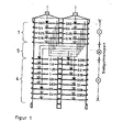
- FIG. 1 shows a cross section through the entire sieve stack of a sieve machine system developed on the basis of a multi-deck sieving machine according to DD 151 882 or EP 028 792, consisting of pre-sieve stack 1, return element 5 and post-sieve stack 4, the sieve stack being longitudinally divided in the middle.
- the entire stack of sieves is firmly clamped to a multi-deck sieving machine in a vibration-stable and dust-tight manner by means of steel cable bracing.
- the feed material is broken down into 5 grain groups:> 63 mm; 0.63 - 0.4 mm; 0.4-0.25mm; 0.25 - 0.16 mm and ⁇ 0.16 mm. This means that both halves of the sieve are covered with identical sieves.
- the grain groups are transported from the discharge side to the feed side opposite to the sieve excitation. It can be seen from FIG. 1 that 2 to 3 grit groups are combined with one another on the right and left half of the sieve.
- the mesh widths are 2 mm on the right half of the sieve; 1.6 mm; 1.25 mm; 1 mm; 0.8 mm; 0.63 mm; 0.5 mm and 0.4 mm and the mesh width 0.315 mm on the left half of the sieve; 0.25 mm; 0.2 mm; 0.16 mm; 0.125 mm; 0.1 mm; 0.08mm and 0.063mm.
- the black arrows indicate the transfer points of grain groups from the feedthroughs to the screen decks of the after-sieve stack 4.
- the screening machine system is basically the same as in the first, but the material to be screened is separated in the following order: pre-screening stacks, return elements, post-screening stacks.
- the grain size distribution density of the feed material can be matched very precisely to the partition surface assignment of the respective mesh sizes and relative free sieve surfaces.
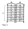
- FIG. 2 shows a screening machine system with a main screening stack 2 which, as in embodiment 1 is divided lengthways.
- the adaptation to the grain size distribution density of a feed is shown, which has high proportions below 0.1 mm.
- the mesh sizes 0.063 mm to 0.16 mm are placed on both sides to offer the screenings more screen area in the fine area.
- the fractions> 0.4 mm (right-hand side) and 0.4 - 0.16 mm (left-hand side) are fed back into the feed material. In this way, the feed material is enriched with certain grain sizes, but these are in the areas in which the screen area offered is not fully utilized.
- Screening aids in the form of rubber or wooden balls have proven to be effective after the installation of a sub-floor with coarse screen fabric to prevent the screen decks from going blind with fine mesh sizes.
- the sieve stack is firmly clamped to the vibration frame by means of clamping screws.
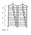
- FIG. 3 shows a screening machine system with several partial screen stacks 3.
- the feed material is broken down into four partial flows on each screen half by means of bushings in the front part of the screen decks.
- These partial flows are each fed to a partial sieve stack, which consists of two sieve decks with 0.4 mm and 0.16 mm mesh size and a blind deck.
- the sieve stack therefore consists of 8 partial sieve stacks with a total of 11 sieve and blind decks.
- This sieve stack is also firmly braced with the vibration frame to a multi-deck screening machine by means of steel cable tensioning, screening aids being provided in the underbody of the screening deck.
Landscapes
- Combined Means For Separation Of Solids (AREA)
- Threshing Machine Elements (AREA)
- Selective Calling Equipment (AREA)
- Breeding Of Plants And Reproduction By Means Of Culturing (AREA)
- Eye Examination Apparatus (AREA)
- Holo Graphy (AREA)
- Non-Silver Salt Photosensitive Materials And Non-Silver Salt Photography (AREA)
Abstract
Die Erfindung bezieht sich auf ein Siebmaschinensystem für eine Mehrdecksiebmaschine, ausgelegt nach dem Wurfsiebprinzip, zur Lösung unterschiedlicher Klassieraufgaben in einer geschlossenen Maschineneinheit. Das erfindungsgemäße Siebmaschinensystem besteht aus den Zonen: Vorsiebstapel, Hauptiebstapel, Teilsiebstapel, Nachsiebstapel und Rückführelement, die gegenseitig austauschbar und ersetzbar sind und zu Systemlösungen zusammensetzbar sind.The invention relates to a screening machine system for a multi-deck screening machine, designed according to the throwing screen principle, for solving different classification tasks in a closed machine unit. The screening machine system according to the invention consists of the zones: pre-screen stack, main screen stack, partial screen stack, post-screen stack and return element, which are mutually interchangeable and replaceable and can be assembled into system solutions.
Description
Die Erfindung bezieht sich auf ein Siebmeschinensystem für eine Mohrdecksiebmaschine, ausgelegt nach dem Wurfsiebprinzip, zur Lösung unterschiedlicher Klassieraufgaben, vorzugsweise mit Trennachnitten im Bereich von 5,0 mm bis 0,04 mm, in einer geschlossenen Maachineneinheit.The invention relates to a screening machine system for a moor deck screening machine, designed according to the throwing screening principle, for solving different classification tasks, preferably with separating cuts in the range from 5.0 mm to 0.04 mm, in a closed machine unit.
Siebmaschinen werden nach ihrer Funktionsweise grundsätzlich in Wurfsiebe und Planaiebe unterteilt. Bei den Wurfsieben erfolgt die Sieberregung in einer senkrechten Komponente zur Siebebene wurfartig. Plansiebe schwingen in der Siebebene. Nähere Ausführungen dazu enthält H. Schubert: Aufbereitung fester minerelisoher Rohstoffe, Bd. I, VEB Deutscher Verlag für Grundstoffindustrie, Leipzig, 3. Auflage. Als Wurfsieb ausgelegte Mehrdecksiebmaschinen sind bereite bekannt. Sie unterscheiden sich hauptsächlich in der oben beschriebenen Art der Sieberregung, weniger in der Zahl der zur VerfUgung stehenden Siebdecks. Allgemein werden Ein- bis höohstens Vierdecksiebe angeboten und verwendet, so daß bis zu 5 Korngrößenklassen gewonnen werden können. Die Begrenzung der Zahl der Siebdecks wird damit begründet, daß mit abnehmender Korngröße bzw. Maschenweite die Siebleietung zurückgeht und damit der Siebmaschinendurchsatz nach der Sieblelstung des feinsten Siebbelages eingestellt werden muß. Ein Vertreter ist dafür der als Plansieb ausgelegte Regula-Freischwinger der Firma J. Engelamann AG, BRD, für eine Klassierung von beispielsweise 8 Korngrößenklassen, bei dem die Siebdecke nicht übereinander angeordnet sind. In einem Rahmen können mehrere Siebebenen, untereinander getrennt,vertikal angeordnet werden. Der Nachteil dieser Siebmaschine besteht in einem großen Flächen- und Raumbedarf. Eine typische Mehrdecksiebmaschine nach dem Plansiebprinzip ist der Planaichter zur Klassierung von Mehl in verschiedene Qualitätsklassen. Er besteht aus einem Spannrahmen, in dem Kaatensiebe und Distanzkammern eingespannt sind. Je nach der Fließfähigkeit des Siebgutea wird der Siebstapel geneigt, um eine Siebgutbewegung von der Einlauf- zur Austragsseite zu erreichen. Durch das Plansiebprinzip ist nur eine begrenzte Produktgruppe ausreichend gut klassierbar. Weiterhin sind Vibrationsrundsiebe als Mehrdecksiebmaschinen bekannt, in denen die Bewegung von Plan- und Wurfsieb vereinigt ist. Ein Vertreter davon ist der Vibrationsseparator der Firma F.B.Lehmann Maschinenfabrik GmbH, BRD. Er führt dreidimensionale Siebbewegungen über 2 Schwungmassen und einen Federkranz aus und erzeugt bis 5 Korngrößenklassen in einer Maschine. Ein ähnlicher Maschinentyp ist die Taumelaiebmaschine, beispielsweise der Firma Allgaier-Werke GmbH, BRD, üblicherweise mit 3 Siebdecks und 4 Korngrößenklassen. Der Nachteil der Vibrationsrundsiebe ist ihre kleine verfügbare Siebfläche von maximal 5 - 6 m2 pro Siebdeck. Alle die genannten Mehrdecksiebmasohinen haben den gemeinsamen Nachteil, daß über eine zentrale Aufgabe das Siebgut aufgegeben wird und entsprechend seiner Korngrößenverteilungadichte und den aufgelegten Siebmeechenweiten eine Klassierung stattfindet, bei der die Siebflächenbelegung einzelner Siebdecks Über- oder unterbelastet wird und damit die Siebgüte bzw. die Trennschärfe des Klessierproduktes beeinträchtigt wird.Screening machines are basically divided into throwing screens and plane screens according to their mode of operation. In the case of the throwing sieves, sieve excitation takes place in a component perpendicular to the sieve plane. Flat sieves vibrate in the sieve plane. H. Schubert contains more detailed information on this: Processing of solid mineral raw materials, Vol. I, VEB German Publishing House for Basic Industry, Leipzig, 3rd edition. Multi-deck screening machines designed as throwing screens are already known. They differ mainly in the type of sieve excitation described above, less in the number of sieve decks available. In general, one to at most four-deck screens are offered and used, so that up to 5 grain size classes can be obtained. The limitation of the number of screen decks is justified by the fact that with decreasing grain size or mesh size the screen rent decreases and thus the screen machine throughput after the screen dissolving finest screen must be set. One representative is the Regula cantilever chair from J. Engelamann AG, FRG, designed as a flat screen, for a classification of, for example, 8 grain size classes, in which the screen cover is not arranged one above the other. Several sieve levels can be arranged vertically in a frame, separated from each other. The disadvantage of this screening machine is that it requires a large amount of space and space. A typical multi-deck sieving machine based on the plane sieve principle is the plan sifter for classifying flour into different quality classes. It consists of a stenter frame, in which cate screens and spacing chambers are clamped. Depending on the flowability of the material to be sieved, the sieve stack is inclined in order to achieve a movement of the material to be sieved from the inlet to the discharge side. Due to the layout screen principle, only a limited product group can be classified sufficiently well. Vibratory rotary screens are also known as multi-deck screening machines, in which the movement of plane and throwing screens is combined. A representative of this is the vibration separator from FBLehmann Maschinenfabrik GmbH, FRG. It performs three-dimensional sieving movements over 2 flywheels and a spring ring and generates up to 5 grain size classes in one machine. A similar machine type is the wobble screening machine, for example from Allgaier-Werke GmbH, FRG, usually with 3 screening decks and 4 grain size classes. The disadvantage of the vibratory rotary screens is their small available screen area of a maximum of 5 - 6 m 2 per screen deck. All the above-mentioned multi-deck screen machines have the common disadvantage that the screenings are given up via a central task and accordingly its grain size distribution density and the applied sieve mesh sizes are classified in such a way that the sieve surface occupancy of individual sieve decks is overloaded or underloaded and thus the sieve quality or the selectivity of the product is impaired.
In der Patentschrift DD 151 882 bzw. EP 0 028 792 wird eine als Wurfsieb ausgelegte Mehrdecksiebmaschine beschrieben, die mit besonderen konstruktiven Merkmalen, wie steiler Sieberregung zwischen 45° bis 85° (Wurfwinkel) und einem Rückfuhrelement ausgezeichnet ist. Damit sind neue Konstruktionselemente im Siebmaschinenbau eingeführt worden, durch die es gelingt, das Siebgut in einer Rückführung entgegen der Transportrichtung erneut zur Aufgabeseite zu fördern und bei einer Vielzahl von Korngrößenklassen eine größere Trennschärfe zu ermöglichen.Patent specification DD 151 882 or EP 0 028 792 describes a multi-deck screening machine designed as a throwing sieve, which is distinguished by special design features such as steep sieve excitation between 45 ° to 85 ° (throwing angle) and a return element. This means that new construction elements have been introduced in the construction of screening machines, through which the material to be screened can be conveyed back to the feed side in a return direction opposite to the direction of transport, and which enables a greater degree of selectivity for a large number of grain size classes.
Es ist aber mit der Entwicklung von Konstruktionselementen noch nicht gelungen, neue Siebmaschinensyateme auf ihrer Basis aufzubauen, mit denen unterschiedlichste Siebprobleme möglichnt in einer Maschineneinheit wirtschaftlich gelöst werden können. Das Wurfsiebprinzip in einer Mehrdecksiebmaschine stößt an Leistungsgrenzen, wenn, wie bereits vorher beschrieben, eine zu hohe oder zu niedrige Siebflächenbalegung auf einzelnen Siebdecka auftritt, die zu Verlusten in der SiebgUte bzw. der Trennschärfe des Klassierprozesses führt. Die Gewinnung einer Vielzahl von Korngrößenklassen, beispielsweise über 10 in einer Mehrdecksiebmasohine, führt bei Veränderungen in der Korngrößenverteilung eines Siebgutes zu Verlusten im Durohsatz und in der Siebgüte, d.h. die Siebmaschine ist nicht ausgelastet und bringt zusätzlich Qualitätsverluste mit sich.However, with the development of construction elements, it has not yet been possible to build new screening machine systems based on them, with which a wide variety of screening problems can be solved economically in one machine unit. The throwing sieve principle in a multi-deck screening machine reaches its performance limits if, as already described, too high or too low screening surface coverage occurs on individual screening decks, which leads to losses in the screening quality or the selectivity of the classification process. Obtaining a large number of grain size classes, for example more than 10 in a multi-deck sieve, leads to changes in the grain size distribution of a material to be sieved, resulting in losses in duro use and in sieving quality, i.e. the sieving machine is not fully utilized and also results in quality losses.
Die Erfindung hat die Aufgabe, ein Siebmaschinenaystem auf der Basis einer nach dem Wurfsiebprinzip arbeitenden Mehrdecksiobmaschine zu entwickeln, mit deren Hilfe Klassieraufgaben in einer einzelnen Masohineneinheit gelöst werden, wenn das Aufgabegut produktionsbedingt in seiner Kornzusammensetzung wechselt, wenn unterschiedliche Siebgüter mit unterschiedlicher Dichte oder Kornform zu klassieren sind oder wenn aus einem Aufgabegut ohne Rücksicht auf dessen Kornverteilung bedarfsgerechte Körnungen zu erzeugen sind. Es ist weiterhin Aufgabe der Erfindung, mit dem Siebmaschinensystem eine gleichmäßige Siebflächenbelegung unter Berücksichtigung der Kornsrößenverteilungsdichte des Aufgabegutes, der jeweiligen Maschenweite und der zugehörigen relativ freien Siebflüche zu erreichen. Diese Aufgabe wird erfindungsgemäß dadurch gelöst, daß der Siebstapel einer nach dem Wurfsiebprinzip ausgebildeten Mehrdecksiebmaschine aus den Zonen: Vorsiebstapel, Hauptsiebstapel, Teilsiebstapel, Nachsiebstapel und Rückführelement besteht, die gegenseitig austauschbar und ersetzbar sind und zu den Systemlösungen
- - Mehrdecksiebmaschine mit einem Vorsiebstapel, Rückführelement und Nachsiebstapel;
- - Mehrdecksiebmaschine mit Vorsiebstapel, Rückführelementen und Nacheiebstapeln;
- - Mehrdecksiebmaschine mit einem Hauptsiebstapel;
- - Mehrdeoksiebmaschine mit mehreren Teilsiebstapeln zusammensetzbar sind.
- - Multi-deck screening machine with a pre-screening stack, return element and post-screening stack;
- - Multi-deck screening machine with pre-screening stacks, return elements and post-screening stacks;
- - Multi-deck screening machine with a main screen stack;
- - Multiple deodorant screen machine can be assembled with several partial screen stacks.
Für dieses Siebmaschinensystem ist weiterhin erfindungswesentlich, daß, bis auf das Rückführelement, jede Zone mindestens aus einem Siebdeok und einem Blinddeck und im System einer Mehrdeoksiebmaschine mit einem Hauptsiebstapel dieser aus mindestens fünf Siebdecks und einem Blinddeok besteht, daß die Sieb- und Blinddecks längsgeteilt und in ihrem Rahmenprofil untereinander stapelbar und gegenseitig abgedichtet sind und daß diese beiden Deckerten an ihrer Einlauf- und Auslaufseite Durchführungen für das Siebgut enthalten, um damit eine Siebgutverteilung innerhalb der Siebmaschine sowie eine Abführung des Siebgutes aus der Siebmaschine zu gewährleisten. Im Fall des Systems mit einem Hauptsiebstapel sind auf mindestens einem Siebdeck beiderseits unterschiedliche Maschenweiten bzw. Siebgewebe aufgelegt.For this screening machine system, it is also essential to the invention that, apart from the return element, each zone consists of at least one screen deok and one blind deck, and in the system of a multi deok screening machine with a main screen stack of at least five Sieve decks and a blind deok exist that the sieve and blind decks are longitudinally divided and stackable and mutually sealed in their frame profile, and that these two decks contain feed-throughs for the material to be sieved on their inlet and outlet sides in order to thereby distribute the material to be sieved within the sieving machine and to remove it to ensure the material to be screened from the screening machine. In the case of the system with a main sieve stack, different mesh sizes or sieve fabrics are placed on both sides of at least one sieve deck.
Die Aufgabe des Rückführelements ist dabei die Förderung des Siebgutes entgegen der Förderrichtung für eine erneute Wiederholung des Siebvorganges zur Einlauf- bzw. Aufgabeseite innerhalb der Siebmaschine. Der Siebstapel, bestehend aus Siebdecks, Blinddecks und, je nach Wahl des Siebsystems, Rückführelementen, wird in einem Schwingungsrahmen mittels eines Stahlseiles oder Spannschrauben schwingungsstabil und staubdicht verspannt.The function of the return element is to convey the material to be screened against the direction of conveyance for a repeated repetition of the screening process to the inlet or feed side within the screening machine. The sieve stack, consisting of sieve decks, blind decks and, depending on the selection of the sieve system, feedback elements, is clamped in a vibration frame by means of a steel cable or tensioning screws in a vibration-stable and dust-tight manner.
Als erfindungswesentlich hat sich weiterhin erwiesen, daß die Siebdecks im Unterboden Siebhilfen enthalten. Bei dem Siebmaschinensystem Vorsiebatapel - Rückführelement - Nachsiebstapel wird im Vorsiebstapel das Aufgabegut in größere Kornkloesenbereiche (Körnungsgruppen) vorklsesiert, um nach der Rückführung im Nachsiebstapel entsprechend dem Klassierverhalten der Siebgüter und deren Korngrößenverteilungsdichte eine optimale Siebflächenbelegung zu erreichen. Mit der zusätzlichen Längsteilung der Siebdecks ist eine weitere Anpassung an die verschiedensten Siebaufgaben gegeben. Dieses Siebmaschinensystem gilt für die Erzeugung einer Vielzahl von Korngrößenklassen.It has also proven to be essential to the invention that the screen decks contain screening aids in the underbody. With the screening machine system pre-screening stack - return element - post-screening stack, the feed material is pre-sorted into larger grain bobbin areas (grit groups) in the pre-screening stack in order to achieve an optimal sieving area occupation after the return in the post-screening stack according to the classification behavior of the screenings and their grain size distribution density. With the additional longitudinal division of the screen decks, further adaptation to a wide variety of screening tasks is possible. This screening machine system applies to the production of a large number of grain size classes.
Bei dem Siebmaschinensystem mit mehreren Teilsiebstapeln sind parallel laufende gleiche Siebvorgänge mit dem Ziel der Erzeugung weniger Korngrößenklassen bei hohem Durchsatz in einer einzelnen Mehrdecksiebmaschine möglich. Bei dem Siebmaachinensystem mit einem Hauptsiebatapel, bestehend aus mindestens 5 Siebdecks und einem Blinddeck wird das Aufgabegut so über die einzelnen Siebdecks geführt, daß für bestimmte Fraktionen, die in dem Aufgabegut angereichert sind, mehr Siebfläche zur Verfügung steht. Auch hier erweist sich die Längsteilung der Siebdecks für eine Anpassung an die Korngrößenverteilungsdichte des Aufgabegutes als sehr positiv, da rechts- und linksseitig unterschiedliche Maschenweiten aufgelegt werden können. Mit dem vorgeschlagenen Siebmaschinensystem auf der Basis einer Mehrdecksiebmaschine können in einer einzelnen Maschineneinheit die aufgabegemäßen Stoffe in hoher Trennschärfe bei niedrigem Raumbedarf, niedrigen Invest- und Unterhaltungskosten und geringem Entstaubungsaufwand klassiert werden. Nachfolgend wird die Erfindung anhand von 4 Ausführungsbeispielen näher erläutert.In the screening machine system with several partial screening stacks, the same screening processes running in parallel are included the goal of producing fewer grain size classes with high throughput in a single multi-deck screening machine. In the sieve machine system with a main sieve stack consisting of at least 5 sieve decks and a blind deck, the feed material is guided over the individual sieve decks in such a way that for certain fractions which are enriched in the feed material, more sieve area is available. Here, too, the longitudinal division of the screen decks proves to be very positive for adaptation to the grain size distribution density of the feed material, since different mesh sizes can be applied on the right and left sides. With the proposed screening machine system based on a multi-deck screening machine, the task-related substances can be classified in a single machine unit with high selectivity with low space requirements, low investment and maintenance costs and low dedusting effort. The invention is explained in more detail below on the basis of 4 exemplary embodiments.
Figur 1 zeigt einen Querschnitt durch den gesamten Siebstapel eines auf der Basis einer Mehrdecksiebmaschine nach DD 151 882 bzw. EP 028 792 entwickelten Siebmaschinensystems, bestehend aus Voraiebstapel 1, Rückführelement 5 und Nachsiebstapel 4, wobei der Siebstapel in der Mitte längsgeteilt ist. Der gesamte Siebstapel wird durch eine Stahlseilverspannung schwingungsstabil und staubdicht im Schwingungsrahmen fest zu einer Mehrdecksiebmaschine verspannt. Im Vorsiebstapel 1, der aus 4 Siebdecks und 1 Blinddeck besteht, wird das Aufgabegut in 5 Körnungsgruppen zerlegt: > 63 mm; 0,63 - 0,4 mm; 0,4 - 0,25 mm; 0,25 - 0,16 mm und <0,16 mm. Damit sind beide Siebhälften mit gleiohen Siebmasohen belegt. Im Rückführelement 5 werden die Körnungogruppen von der Austregeseite zur Aufgaboseite entgegengesetzt der Sieberregung transportiert. Dabei ist aus der Figur 1 zu entnehmen, daß jeweils 2 bis 3 Körnungsgruppen auf der rechten bzw. linken Siebhälfte miteinander vereinigt werden. Im Nachsiebstapel 4 sind auf der rechten Siebhälfte die Manchenweiten 2 mm; 1,6 mm; 1,25 mm; 1 mm; 0,8 mm; 0,63 mm; 0,5 mm und 0,4 mm aufgelegt und auf der linken Siebhälfte die Maschenweiten 0,315 mm; 0,25 mm; 0,2 mm; 0,16 mm; 0,125 mm; 0,1 mm; 0,08 mm und 0,063 mm. Durch die schwarzen Pfeile werden die Überführungsstellen von Körnungsgruppen aus den Durchführungen auf die Siebdecks des Nachsiebstapels 4 gekennzeichnet. Mit der Fostlegung der Trennschnitte im Vorsiebstapel 1 und der Aufteilung der Körnungsgruppen im Nachsiebstapel 4 mit seiner zusätzlichen Unterteilung in eine rechte und eine linke Seite wird die gute Anpassung an sehr unterschiedliche Siebgüter unter Berücksichtigung der Korngrößenverteilungsdichte des Autgabegutes, der jeweiligen Maschenweite und der zugehörigen relativen freien Siebfläche sichtbar, wodurch die notwendige gleichmäßige Siebflächenbelegung erreicht wird.FIG. 1 shows a cross section through the entire sieve stack of a sieve machine system developed on the basis of a multi-deck sieving machine according to DD 151 882 or EP 028 792, consisting of
Beim zweiten Ausführungsweg ist das Siebmaschinensystem prinzipiell wie im ersten ausgeführt, jedoch erfolgt die Trennung des Siebgutes in der Reihenfolge: Vorsiebstapel, Rückführelemente, Nachsiebstapeln. Auch hier gelingt sehr genau eine Abstimmung der Korngrößenverteilungsdichte des Aufgabegutes auf die Trennflächenbelegung der jeweiligen Maschenweiten und relativen freien Siebflächen.In the second embodiment, the screening machine system is basically the same as in the first, but the material to be screened is separated in the following order: pre-screening stacks, return elements, post-screening stacks. Here, too, the grain size distribution density of the feed material can be matched very precisely to the partition surface assignment of the respective mesh sizes and relative free sieve surfaces.
Figur 2 zeigt ein Siebmaschinensystem mit einem Hnuptsiebstapel 2, der wie im Ausführungsbeispiel 1 längsgeteilt ist. Hier wird die Anpassung an die Korngrößenverteilungsdichte eines Aufgabegutes gezeigt, das hohe Anteile unter 0,1 mm aufweiat. Die Maschenweite 0,063 mm bis 0,16 mm sind beiderseits aufgelegt, um dem Siebgut im Feinbereich mehr Siebfläche anzubieten. Die Fraktionen >0,4 mm (rechtsseitig) und 0,4 - 0,16 mm (linksseitig) werden dem Aufgabegut wieder zugeführt. Auf diese Weise wird das Aufgabegut mit bestimmten Körnungen angereichert, diese liegen aber in den Bereichen, in denen die angebotene Siebfläche nicht ausgelastet ist. Als effektiv haben sich nach Anbringen eines Unterbodens mit grobem Siebgewebe Siebhilfen in Form von Gummi- oder Holzkugeln zur Verhinderung des Erblindens der Siebdecks mit feinen Maschenweiten erwiesen. Der Siebatapel wird mittels Spannschrauben fest mit dem Schwingungsrahmen verspannt.FIG. 2 shows a screening machine system with a
Figur 3 zeigt ein Siebmaschinensystem mit mehreren Teilsiebstapeln 3. Das Aufgabegut wird mittels Durchführungen im Vorderteil der Siebdecks in vier Teilströme auf jeder Siebhälfte zerlegt. Diese Teilströms werden je einem Teilsiebstapel zugeführt, der aus 2 Siebdecks mit 0,4 mm und 0,16 mm Maschenweite und einem Blinddeck besteht. Der Siebatapel besteht folglich aus 8 Teilsiebatapeln zu insgesamt 11 Sieb- und Blinddecks. Dieser Siebstapel wird ebenfalls mittels einer Stahlseilverspannung fest mit dem Schwingungsrahmen zu einer Mehrdecksiebmaschine verspannt, wobei Siebhilfen im Unterboden des Siebdecks vorgesehen wurden.FIG. 3 shows a screening machine system with several partial screen stacks 3. The feed material is broken down into four partial flows on each screen half by means of bushings in the front part of the screen decks. These partial flows are each fed to a partial sieve stack, which consists of two sieve decks with 0.4 mm and 0.16 mm mesh size and a blind deck. The sieve stack therefore consists of 8 partial sieve stacks with a total of 11 sieve and blind decks. This sieve stack is also firmly braced with the vibration frame to a multi-deck screening machine by means of steel cable tensioning, screening aids being provided in the underbody of the screening deck.
Claims (7)
zusammensetzbar sind.1. Screening machine system, designed as a multi-deck screening machine according to the throwing principle, with screen decks clamped in oscillating frames, blind decks and return elements as a screening stack and with a vibration exciter arranged on the screening stack, characterized in that the screening stack consists of the zones: pre-screening stack (1), main screening stack (2), Partial sieve stack (3), secondary sieve stack (4) and feedback element (5), which are mutually interchangeable and replaceable and to the system solutions
can be put together.
Priority Applications (1)
| Application Number | Priority Date | Filing Date | Title |
|---|---|---|---|
| AT86105946T ATE70743T1 (en) | 1985-09-23 | 1986-04-30 | SCREENING SYSTEM. |
Applications Claiming Priority (2)
| Application Number | Priority Date | Filing Date | Title |
|---|---|---|---|
| DD85280888A DD256227A3 (en) | 1985-09-23 | 1985-09-23 | type of screen |
| DD280888 | 1985-09-23 |
Publications (3)
| Publication Number | Publication Date |
|---|---|
| EP0216005A2 true EP0216005A2 (en) | 1987-04-01 |
| EP0216005A3 EP0216005A3 (en) | 1988-10-12 |
| EP0216005B1 EP0216005B1 (en) | 1991-12-27 |
Family
ID=5571487
Family Applications (1)
| Application Number | Title | Priority Date | Filing Date |
|---|---|---|---|
| EP86105946A Expired - Lifetime EP0216005B1 (en) | 1985-09-23 | 1986-04-30 | Screening machine |
Country Status (5)
| Country | Link |
|---|---|
| EP (1) | EP0216005B1 (en) |
| JP (1) | JPS6268575A (en) |
| AT (1) | ATE70743T1 (en) |
| DD (1) | DD256227A3 (en) |
| DE (1) | DE3683110D1 (en) |
Cited By (1)
| Publication number | Priority date | Publication date | Assignee | Title |
|---|---|---|---|---|
| US8844729B2 (en) | 2006-09-25 | 2014-09-30 | Basf Se | Method for grading water-absorbent polymer particles |
Families Citing this family (1)
| Publication number | Priority date | Publication date | Assignee | Title |
|---|---|---|---|---|
| GB2444996A (en) * | 2006-11-22 | 2008-06-25 | Toshiba Res Europ Ltd | Inter-Relay Interference Avoidance in a Wireless Communications Network |
Family Cites Families (2)
| Publication number | Priority date | Publication date | Assignee | Title |
|---|---|---|---|---|
| DD151882A1 (en) * | 1979-11-08 | 1981-11-11 | Dressler Ernst Heinrich | multi deck |
| JPS61138574A (en) * | 1984-12-11 | 1986-06-26 | 株式会社 サタケ | Spiral conveyor for vertical type selector |
-
1985
- 1985-09-23 DD DD85280888A patent/DD256227A3/en not_active IP Right Cessation
-
1986
- 1986-04-30 DE DE8686105946T patent/DE3683110D1/en not_active Expired - Lifetime
- 1986-04-30 EP EP86105946A patent/EP0216005B1/en not_active Expired - Lifetime
- 1986-04-30 AT AT86105946T patent/ATE70743T1/en not_active IP Right Cessation
- 1986-09-22 JP JP61222238A patent/JPS6268575A/en active Pending
Cited By (2)
| Publication number | Priority date | Publication date | Assignee | Title |
|---|---|---|---|---|
| US8844729B2 (en) | 2006-09-25 | 2014-09-30 | Basf Se | Method for grading water-absorbent polymer particles |
| EP2076338B2 (en) † | 2006-09-25 | 2022-01-26 | Basf Se | Method for grading water-absorbent polymer particles |
Also Published As
| Publication number | Publication date |
|---|---|
| EP0216005B1 (en) | 1991-12-27 |
| JPS6268575A (en) | 1987-03-28 |
| DD256227A3 (en) | 1988-05-04 |
| ATE70743T1 (en) | 1992-01-15 |
| EP0216005A3 (en) | 1988-10-12 |
| DE3683110D1 (en) | 1992-02-06 |
Similar Documents
| Publication | Publication Date | Title |
|---|---|---|
| DE69017835T2 (en) | Twin-screen grain classifier and method. | |
| EP0584302B1 (en) | Device for plansifter | |
| DE69418785T2 (en) | Sorting device for non-ferrous materials | |
| AT6073U1 (en) | multi deck | |
| WO1998036854A1 (en) | Frame for flat sifter and process for producing the same | |
| DE102009032689B3 (en) | Sieve machine e.g. vibration sieve machine, for classification or sorting of excavated material into individual components in industry, has sieving body provided with sieve, which exhibits rectangular base form | |
| EP1480763B1 (en) | Sifting device | |
| DE1196946B (en) | Sieving machine | |
| DE3741924A1 (en) | VIBRATION SCREENER | |
| EP0028792B1 (en) | Multi-deck screening machine | |
| EP0216005B1 (en) | Screening machine | |
| DE2923662C2 (en) | Vibrating screen, especially circular vibrating screen | |
| DE19517850C2 (en) | Screening machine for pre-sorting material mixtures | |
| DE102020125280B3 (en) | Vibrating screening machine | |
| DE3043497C2 (en) | Vibrating screening machine | |
| DE69119228T2 (en) | Method and device for screening granular materials | |
| DE602004011125T2 (en) | STRUCTURAL ARRANGEMENT FOR SWING FACILITIES | |
| EP0824972B1 (en) | Method for separating a mixture of solids | |
| EP0992293B1 (en) | Screen, more particularly wobbling screen | |
| DE102006020215A1 (en) | Fractionating paper fiber suspensions, to give fiber-enriched and fines-enriched fractions, by wet sieving to obtain long and short fiber fractions and further wet sieving short fiber fraction | |
| DE4012802A1 (en) | Operating system for multi-deck sieve - has superimposed vibrations to ensure sieving of lump-forming materials | |
| DE971791C (en) | Device for dewatering pulp suspensions | |
| EP0482566B1 (en) | Screen for separating materials of different weights | |
| DE19526841C1 (en) | Solids sepn. according to shape | |
| DE8910068U1 (en) | Multi-stage sieve |
Legal Events
| Date | Code | Title | Description |
|---|---|---|---|
| PUAI | Public reference made under article 153(3) epc to a published international application that has entered the european phase |
Free format text: ORIGINAL CODE: 0009012 |
|
| AK | Designated contracting states |
Kind code of ref document: A2 Designated state(s): AT BE CH DE GB LI SE |
|
| PUAL | Search report despatched |
Free format text: ORIGINAL CODE: 0009013 |
|
| AK | Designated contracting states |
Kind code of ref document: A3 Designated state(s): AT BE CH DE GB LI SE |
|
| 17P | Request for examination filed |
Effective date: 19890313 |
|
| 17Q | First examination report despatched |
Effective date: 19900216 |
|
| GRAA | (expected) grant |
Free format text: ORIGINAL CODE: 0009210 |
|
| AK | Designated contracting states |
Kind code of ref document: B1 Designated state(s): AT BE CH DE GB LI SE |
|
| REF | Corresponds to: |
Ref document number: 70743 Country of ref document: AT Date of ref document: 19920115 Kind code of ref document: T |
|
| REF | Corresponds to: |
Ref document number: 3683110 Country of ref document: DE Date of ref document: 19920206 |
|
| GBT | Gb: translation of ep patent filed (gb section 77(6)(a)/1977) | ||
| PLBE | No opposition filed within time limit |
Free format text: ORIGINAL CODE: 0009261 |
|
| STAA | Information on the status of an ep patent application or granted ep patent |
Free format text: STATUS: NO OPPOSITION FILED WITHIN TIME LIMIT |
|
| 26N | No opposition filed | ||
| PGFP | Annual fee paid to national office [announced via postgrant information from national office to epo] |
Ref country code: CH Payment date: 19930308 Year of fee payment: 8 |
|
| PGFP | Annual fee paid to national office [announced via postgrant information from national office to epo] |
Ref country code: SE Payment date: 19930309 Year of fee payment: 8 |
|
| PGFP | Annual fee paid to national office [announced via postgrant information from national office to epo] |
Ref country code: BE Payment date: 19930420 Year of fee payment: 8 |
|
| PGFP | Annual fee paid to national office [announced via postgrant information from national office to epo] |
Ref country code: GB Payment date: 19930422 Year of fee payment: 8 |
|
| PGFP | Annual fee paid to national office [announced via postgrant information from national office to epo] |
Ref country code: AT Payment date: 19930423 Year of fee payment: 8 |
|
| PGFP | Annual fee paid to national office [announced via postgrant information from national office to epo] |
Ref country code: DE Payment date: 19930629 Year of fee payment: 8 |
|
| PG25 | Lapsed in a contracting state [announced via postgrant information from national office to epo] |
Ref country code: LI Effective date: 19940430 Ref country code: GB Effective date: 19940430 Ref country code: CH Effective date: 19940430 Ref country code: BE Effective date: 19940430 Ref country code: AT Effective date: 19940430 |
|
| PG25 | Lapsed in a contracting state [announced via postgrant information from national office to epo] |
Ref country code: SE Effective date: 19940501 |
|
| BERE | Be: lapsed |
Owner name: AKADEMIE DER WISSENSCHAFTEN DER DDR Effective date: 19940430 |
|
| REG | Reference to a national code |
Ref country code: CH Ref legal event code: PL |
|
| PG25 | Lapsed in a contracting state [announced via postgrant information from national office to epo] |
Ref country code: DE Effective date: 19950103 |
|
| GBPC | Gb: european patent ceased through non-payment of renewal fee |
Effective date: 19940430 |
|
| EUG | Se: european patent has lapsed |
Ref document number: 86105946.7 Effective date: 19941210 |
|
| EUG | Se: european patent has lapsed |
Ref document number: 86105946.7 |