EP0215752A2 - Kolbenpumpe, insbesondere um Reifen, Matratzen, Sportausrüstungen usw. aufzupumpen - Google Patents
Kolbenpumpe, insbesondere um Reifen, Matratzen, Sportausrüstungen usw. aufzupumpen Download PDFInfo
- Publication number
- EP0215752A2 EP0215752A2 EP86830256A EP86830256A EP0215752A2 EP 0215752 A2 EP0215752 A2 EP 0215752A2 EP 86830256 A EP86830256 A EP 86830256A EP 86830256 A EP86830256 A EP 86830256A EP 0215752 A2 EP0215752 A2 EP 0215752A2
- Authority
- EP
- European Patent Office
- Prior art keywords
- piston
- cylinder
- chambers
- opening
- valve member
- Prior art date
- Legal status (The legal status is an assumption and is not a legal conclusion. Google has not performed a legal analysis and makes no representation as to the accuracy of the status listed.)
- Withdrawn
Links
Images
Classifications
-
- F—MECHANICAL ENGINEERING; LIGHTING; HEATING; WEAPONS; BLASTING
- F01—MACHINES OR ENGINES IN GENERAL; ENGINE PLANTS IN GENERAL; STEAM ENGINES
- F01L—CYCLICALLY OPERATING VALVES FOR MACHINES OR ENGINES
- F01L21/00—Use of working pistons or pistons-rods as fluid-distributing valves or as valve-supporting elements, e.g. in free-piston machines
- F01L21/02—Piston or piston-rod used as valve members
-
- F—MECHANICAL ENGINEERING; LIGHTING; HEATING; WEAPONS; BLASTING
- F04—POSITIVE - DISPLACEMENT MACHINES FOR LIQUIDS; PUMPS FOR LIQUIDS OR ELASTIC FLUIDS
- F04B—POSITIVE-DISPLACEMENT MACHINES FOR LIQUIDS; PUMPS
- F04B33/00—Pumps actuated by muscle power, e.g. for inflating
- F04B33/02—Pumps actuated by muscle power, e.g. for inflating with intermediate gearing
-
- F—MECHANICAL ENGINEERING; LIGHTING; HEATING; WEAPONS; BLASTING
- F04—POSITIVE - DISPLACEMENT MACHINES FOR LIQUIDS; PUMPS FOR LIQUIDS OR ELASTIC FLUIDS
- F04B—POSITIVE-DISPLACEMENT MACHINES FOR LIQUIDS; PUMPS
- F04B39/00—Component parts, details, or accessories, of pumps or pumping systems specially adapted for elastic fluids, not otherwise provided for in, or of interest apart from, groups F04B25/00 - F04B37/00
- F04B39/0005—Component parts, details, or accessories, of pumps or pumping systems specially adapted for elastic fluids, not otherwise provided for in, or of interest apart from, groups F04B25/00 - F04B37/00 adaptations of pistons
- F04B39/0016—Component parts, details, or accessories, of pumps or pumping systems specially adapted for elastic fluids, not otherwise provided for in, or of interest apart from, groups F04B25/00 - F04B37/00 adaptations of pistons with valve arranged in the piston
Definitions
- the present invention refers to piston pumps and relates particularly to a piston pump for pumping fluids, comprising:
- a pump of the above-specified type is known in which the rod comprises two co-axial ducts, intake and delivery respectively, and in which two one-way disc valves are mounted on each of the two faces of the piston, operating in opposite directions and communicating respectively with the intake duct and the delivery duct.
- the present invention has the object of providing a piston pump of the above-specified type, which is improved in terms of efficiency and convenience of use, and does not give rise to the drawbacks in use described above.
- this object is achieved by means of a piston pump of the type specified above, characterised in that it includes a further valve member associated with one of the two chambers and selectively openable so as to put the said one of the two chambers into free communication with the outside of the cylinder.
- the decrease in the volume of the corresponding pumping chamber causes only the discharge of the pumped fluid (typically air) from the cylinder and not the supply of the delivery duct. Under such conditions, the pump actually behaves as a single-action pump.
- the pumped fluid typically air
- the further valve member will be associated with the chamber which is in the upper position in use.
- the user will be able to actuate the further valve element so as to cause the pump to operate as a single-acting pump and perform the pumping action only when the piston is pushed downwardly towards the ground.
- the raising of the piston (which does not involve the performance of a pumping action) may be carried out easily without excessive effort.
- a piston pump preferably intended to be used for the inflation of tyres, mattresses, sports equipment, and the like is generally indicated 1.
- the pump 1 comprises, as component parts:
- the rod 5 has two internal ducts 8 and 9, intake and delivery respectively, which open into two corresponding inlet and outlet openings 10, 11 at the upper end of the rod 5.
- a pipe union is normally associated with the latter opening which enables the pump 1 to be connected to a tube or sleeve for connection to the inflatable article (tyre, mattress, item of sports equipment, etc) to be inflated.
- the opening 10 may also have a pipe union which it is possible to connect to a tube or sleeve ending at an inflatable item whose deflation it is desired to speed up.
- the intake and delivery ducts 8, 9 may be constructed in different ways, account being taken of the structure of the rod 5 which is normally cylindrical.
- the ducts 8 and 9 may be two ducts of semi-circular section placed side by side. It is also possible to adopt a coaxial arrangement, with an inner duct of circular section and an outer duct of annular section.
- the arrangement of the openings 10 and 11, which are shown side by side for convenience of representation, is adapted to the structure of ducts 8 and 9.
- the piston 4 is generally hollow and has internal septa or partitions which divide it into two volumes 12, 13 sealed from each other.
- the piston 9 divides the cylinder 1 into two chambers 14, 15 which are superposed in the normal arrangement of use of the pump 1.
- the intake volume 12 of piston 4 communicates with the lower chamber 15 of the cylinder 2 through an opening in which a one-way valve 16 with disc or discoidal shutter is interposed.
- the function of the valve 16 is to allow the flow of pumping fluid (normally air) from the volume 12 to the chamber 15 but to prevent flow in the opposite direction.
- the movement of the shutter of the valve 16 is controlled by the pressure gradient established between the volume 12 and the chamber 15 in such a manner that the valve 16 closes when the pressure in the chamber 15 exceeds the pressure in the volume 12 and opens when the pressure gradient is reversed.
- the volume 13 of the piston 4 communicates with the upper chamber 14 through an opening in which a one-way valve 17 is interposed and with the lower chamber 15 through a further opening in which a one-way valve 18 is interposed.
- the valves 17 and 18 also are of the disc-shutter type and are preferably fitted with a single common shutter 178 of cylindrical shape, one end of which acts as a shutter for the valve 17 and the opposite end of which acts as a shutter for valve 18.
- the valves 17 and 18 are mounted on the piston 4 in such a manner as to allow the pumping fluid to flow towards the delivery duct 9 from the chamber 14 or the chamber 15 in alternation, preventing flow in the opposite direction in each case.
- valves 17 and 18 The mounting arrangement of the valves 17 and 18 on the piston 4 is, so to speak, reversed with respect to the valve 16. This result is normally obtained by arranging the disc shutter of the valve 16 outside piston 4 and the common shutter 178 of the valves 17 and 18 inside the piston.
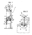
- a further valve with a disc or discoidal shutter is indicated 19 and is mounted on the cover or end 6 which closes cylinder 2 at its upper end.
- valve 19 is associated with an opening 20 which allows communication between the chamber 14 and the outside of the pump.
- a pin-shaped body, indicated 21 extends through the opening 20 and is movable between a first operating position, shown in full outline and indicated A in Figure 2, and a second operating position, shown in broken outline and indicated B in Figure 2.
- the pin 21 is slidably mounted within a tubular sleeve 22 held in a central position relative to the opening 20 by radial spokes, not clearly shown in the drawings.
- a disc shutter 24 similar in every respect to the shutters of the valves 16, 17 and 18.
- the movement of the shutter 24 is controlled by the pressure gradient established through the respective opening 20.
- the shutter 24 is moved away from the opening 20 so as to open it.
- the amplitude of the movement of the shutter 20 between the position of closure of the opening 20 and the position of disengagement from the opening 20 is chosen so that, when the pin 21 is pressed inwardly of the cylinder 2 towards position B, the shutter 24 is any case disengaged from the opening 20 so as always to keep it open.
- the shutter of the valve 16 is pushed into its closure position to interrupt the communication between the intake duct 8 and the chamber 15.
- the shutter 24 of the valve 19 moves into its open position, whereby air can flow freely into the chamber 14 from the outside.
- the shutter 178 is pushed into the position of opening of the valve 18 to put the chamber 15 (which acts at this time as a pumping chamber) into communication with the volume 13 and the delivery duct 9. At the same time, the shutter 178 closes the valve 17 to interrupt communication between the chamber 14 and the delivery duct 9.
- the pressure level in the latter thus tends to increase, while the pressure level in the chamber 15,whose dimensions increase, tends to decrease.
- the shutter of the valve 16 is brought into its open position, whereby the pumping fluid from the intake duct 8 can pass freely into the chamber 15.
- the shutter 24 of the valve 19 is pressed into its closure position to close the opening 20.
- the shutter 178 is pushed into the position of opening the valve 17, which puts the chamber 14 into communication between the chamber 15 and the delivery duct 9.
- valves 16, 17 and 18 take up the same positions of operation as described above.
- valve 19, which is in the open position during the downstroke of the piston 4 are also reproduced, so that the pump performs the normal pumping action.
- valves 16 and 18 are brought respectively to the open and closed positions (as in the case of double-acting operation), and the pumping fluid flows in through the intake duct 8 towards the chamber 15.
- the raising of the piston 4 does not therefore involve the considerable effort which would be required, however, if the pump were operating as a double-acting pump.
- the user has the means for selectively limiting the pumping action to only the downstroke of the piston 4 which, being performed with the user's weight bearing on the rod 5, is less tiring for the back muscles.
- the further valve member 19 enables the selective control of the intake of air into the chamber 14, without the need to provide a corresponding valve on the piston 4 for this purpose.
- the one-way valve 17 which selectively controls the communication between the chamber 14 and the delivery duct 9 is in fact mounted on the face of the piston 4 facing the chamber 14. In this way, a further advantage is obtained over the double-acting pumps of known type, deriving from the elimination of one of the valves mounted on the piston.
- a piston pump has thus been described which can be operated selectively in two modes or types of operation, it being switched selectively from use as a double-acting pump to use as a single-acting pump.
Landscapes
- Engineering & Computer Science (AREA)
- Mechanical Engineering (AREA)
- General Engineering & Computer Science (AREA)
- Reciprocating Pumps (AREA)
- Compressors, Vaccum Pumps And Other Relevant Systems (AREA)
Applications Claiming Priority (2)
| Application Number | Priority Date | Filing Date | Title |
|---|---|---|---|
| IT5382785U IT8553827V0 (it) | 1985-09-20 | 1985-09-20 | Pompa a stantuffo particolarmente per il gonfiaggio di gommoni materassini attrezzi sportivi e simili |
| IT5382785U | 1985-09-20 |
Publications (2)
| Publication Number | Publication Date |
|---|---|
| EP0215752A2 true EP0215752A2 (de) | 1987-03-25 |
| EP0215752A3 EP0215752A3 (de) | 1989-03-08 |
Family
ID=11285424
Family Applications (1)
| Application Number | Title | Priority Date | Filing Date |
|---|---|---|---|
| EP86830256A Withdrawn EP0215752A3 (de) | 1985-09-20 | 1986-09-17 | Kolbenpumpe, insbesondere um Reifen, Matratzen, Sportausrüstungen usw. aufzupumpen |
Country Status (2)
| Country | Link |
|---|---|
| EP (1) | EP0215752A3 (de) |
| IT (1) | IT8553827V0 (de) |
Cited By (4)
| Publication number | Priority date | Publication date | Assignee | Title |
|---|---|---|---|---|
| GB2190150B (en) * | 1986-04-04 | 1989-11-29 | Lucisano F & C Srs Snc | Hand-operated pump |
| AP505A (en) * | 1992-11-20 | 1996-07-12 | VAN NIEKERK Hendrik Cornelius | Pump. |
| CN103953525A (zh) * | 2014-04-21 | 2014-07-30 | 侯如升 | 一种防滑打气筒底座 |
| CN104196697A (zh) * | 2014-07-14 | 2014-12-10 | 格力休闲体育用品有限公司 | 双向手拉气筒活塞 |
Family Cites Families (3)
| Publication number | Priority date | Publication date | Assignee | Title |
|---|---|---|---|---|
| US1697734A (en) * | 1927-07-25 | 1929-01-01 | William Kuhrt | Air pump |
| DE1703474A1 (de) * | 1967-05-29 | 1972-02-03 | Stiga Verken Ab | Doppelwirkende Kolbenpumpe fuer gasfoermige oder fluessige Medien |
| DE2005339C3 (de) * | 1969-02-11 | 1978-06-01 | Ferdinando Mailand Castiglioni (Italien) | Handkolbenpumpe |
-
1985
- 1985-09-20 IT IT5382785U patent/IT8553827V0/it unknown
-
1986
- 1986-09-17 EP EP86830256A patent/EP0215752A3/de not_active Withdrawn
Cited By (4)
| Publication number | Priority date | Publication date | Assignee | Title |
|---|---|---|---|---|
| GB2190150B (en) * | 1986-04-04 | 1989-11-29 | Lucisano F & C Srs Snc | Hand-operated pump |
| AP505A (en) * | 1992-11-20 | 1996-07-12 | VAN NIEKERK Hendrik Cornelius | Pump. |
| CN103953525A (zh) * | 2014-04-21 | 2014-07-30 | 侯如升 | 一种防滑打气筒底座 |
| CN104196697A (zh) * | 2014-07-14 | 2014-12-10 | 格力休闲体育用品有限公司 | 双向手拉气筒活塞 |
Also Published As
| Publication number | Publication date |
|---|---|
| IT8553827V0 (it) | 1985-09-20 |
| EP0215752A3 (de) | 1989-03-08 |
Similar Documents
| Publication | Publication Date | Title |
|---|---|---|
| US5450924A (en) | Portable oil suction device | |
| US5860795A (en) | Method for underground-reservoir fluids production with pump drive contained within the wellbore | |
| US4008008A (en) | Pumps | |
| US1754975A (en) | Nonreturn valve | |
| EP0183360A1 (de) | Hydraulische Hebevorrichtung für einen Stuhl | |
| US5431229A (en) | Method and apparatus for utilizing the pressure of a fluid column generated by a pump to assist in reciprocating the pump plunger | |
| EP0215752A2 (de) | Kolbenpumpe, insbesondere um Reifen, Matratzen, Sportausrüstungen usw. aufzupumpen | |
| US5322101A (en) | Balloon stuffing device | |
| US5885061A (en) | Pneumatic pump | |
| US4842489A (en) | Hand-operated pump changeable from dual action to single action | |
| US20050053503A1 (en) | Anti gas-lock pumping system | |
| CA2310525C (en) | Pilot control valve for controlling a reciprocating pump | |
| US2990816A (en) | Pressure fluid operated pumping mechanism | |
| US3945774A (en) | Anchorable pack-off assembly | |
| US2262128A (en) | Double acting pump | |
| GB2100362A (en) | Submersible hydraulic bore and pressure or negative pressure is well pump | |
| US4221551A (en) | Sliding valve pump | |
| US4243361A (en) | Standing valve assembly for an oil well pump | |
| US2628565A (en) | Fluid operated reciprocating pump for drilled wells | |
| US2214343A (en) | Well pump | |
| US3470821A (en) | Double piston differential type pump | |
| US1120998A (en) | Pump-cylinder. | |
| US3838945A (en) | Pump | |
| US1771070A (en) | Pump | |
| US1721127A (en) | Pump |
Legal Events
| Date | Code | Title | Description |
|---|---|---|---|
| PUAI | Public reference made under article 153(3) epc to a published international application that has entered the european phase |
Free format text: ORIGINAL CODE: 0009012 |
|
| AK | Designated contracting states |
Kind code of ref document: A2 Designated state(s): AT BE CH DE FR GB IT LI LU NL SE |
|
| PUAL | Search report despatched |
Free format text: ORIGINAL CODE: 0009013 |
|
| AK | Designated contracting states |
Kind code of ref document: A3 Designated state(s): AT BE CH DE FR GB IT LI LU NL SE |
|
| STAA | Information on the status of an ep patent application or granted ep patent |
Free format text: STATUS: THE APPLICATION IS DEEMED TO BE WITHDRAWN |
|
| 18D | Application deemed to be withdrawn |
Effective date: 19890331 |
|
| RIN1 | Information on inventor provided before grant (corrected) |
Inventor name: STROPPIANA, FIORINDO |