EP0215587A2 - Kalibrierung von Unterteilen - Google Patents
Kalibrierung von Unterteilen Download PDFInfo
- Publication number
- EP0215587A2 EP0215587A2 EP86306484A EP86306484A EP0215587A2 EP 0215587 A2 EP0215587 A2 EP 0215587A2 EP 86306484 A EP86306484 A EP 86306484A EP 86306484 A EP86306484 A EP 86306484A EP 0215587 A2 EP0215587 A2 EP 0215587A2
- Authority
- EP
- European Patent Office
- Prior art keywords
- change
- actuating member
- component
- state
- switch
- Prior art date
- Legal status (The legal status is an assumption and is not a legal conclusion. Google has not performed a legal analysis and makes no representation as to the accuracy of the status listed.)
- Withdrawn
Links
Images
Classifications
-
- H—ELECTRICITY
- H01—ELECTRIC ELEMENTS
- H01H—ELECTRIC SWITCHES; RELAYS; SELECTORS; EMERGENCY PROTECTIVE DEVICES
- H01H11/00—Apparatus or processes specially adapted for the manufacture of electric switches
- H01H11/0062—Testing or measuring non-electrical properties of switches, e.g. contact velocity
-
- Y—GENERAL TAGGING OF NEW TECHNOLOGICAL DEVELOPMENTS; GENERAL TAGGING OF CROSS-SECTIONAL TECHNOLOGIES SPANNING OVER SEVERAL SECTIONS OF THE IPC; TECHNICAL SUBJECTS COVERED BY FORMER USPC CROSS-REFERENCE ART COLLECTIONS [XRACs] AND DIGESTS
- Y10—TECHNICAL SUBJECTS COVERED BY FORMER USPC
- Y10T—TECHNICAL SUBJECTS COVERED BY FORMER US CLASSIFICATION
- Y10T29/00—Metal working
- Y10T29/49—Method of mechanical manufacture
- Y10T29/49002—Electrical device making
- Y10T29/49105—Switch making
Definitions
- This invention relates to the calibration of mechanically moving components on an automatic production basis so as to ensure consistency of behaviour between one component and the next.
- the aim of the invention is therefore to devise a way of manufacturing switches, and possibly other devices actuated by a mechanical movement, so that each product has the same operating position (i.e. in the case of a micro-switch it operates at the same position of the button relative to the housing), yet without requiring expensive manual adjustment procedures or selection by tolerance bands.
- actuating member e.g. the button
- each product is taken in turn and actuated by progressive displacement of that member, whilst monitoring for the 'operate' instant, and then as soon as operation takes place the actuating member is gripped and cut, or otherwise deformed, so that the resulting actuating surface of that member is at a predetermined geometrical position in relation to the remainder, e.g. the housing, of the product.
- the switch In the case of a micro-switch actuated by a push button, for example, the switch is placed in a jig which automatically makes electrical contact with appropriate terminals of the switch, and then the button is depressed by a plunger; as soon as it snaps over, as detected by a circuit connected to the terminals, a jaw moves in laterally to clamp the button against a fixed jaw, and then the button is cut to length, for example by a saw or broach of which the cutting path bears a fixed relationship to the position occupied by the housing of the switch in the jig.
- this process can be made entirely automatic, including loading and unloading of the jig, and so it can be incorporated in existing production installations without requiring any additional labour, skilled or unskilled, and without slowing down production. Yet trials indicate that the invention will result in switches being produced to tolerances which are about one fifteenth of those accepted in the normal production process.
- the switch 1 is of basically well-known kind, such as that described in U.S. Patent Specification No. 3,965,316, although it could be of any similar kind, having an actuating button 2, movement of which inwards with respect to the housing 3 of the switch causing an internal moving contact, at a certain stage in that movement, to snap over suddenly from engagement with a contact connected to a terminal 4 to engagement with a contact connected to terminal 5.
- the moving contact is itself connected to terminal 6.
- the switch has holes 7 at predetermined standard positions to receive screws or studs by which it is mounted.
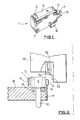
- the switch 1 is placed on its side and accurately located in a predetermined position in a fixture 8 ( Figure 2) by the engagement of pins 9 in the mounting holes 7.
- the fixture 8 may be part of an indexing or conveyor system designed for automatic loading and unloading, and with this in mind there is an ejecting pin 10 in the fixture.
- a fixed jaw or anvil 11 on the fixture lies immediately below one side face of the actuating button 2 of the switch, but without interfering with its movement.
- the terminals 6 and 4 or 5 of the switch (not shown in Figure 2) are in electrical contact with conductors (not shown).
- each switch is brought in turn from a loading station by the fixture and comes to rest adjacent a calibrating head 12, to be described, and in this position the conductors are connected to a control circuit.
- the head 12 descends to clamp the switch 1 to the fixture and to bring an anvil 13 in line with the button 2.
- the anvil 13 then advances to the left, engaging the button 2 and depressing it.
- the control detects that the switch has operated, it halts the anvil 13 and advances a sliding jaw 14 to clamp the button 2 against the fixed jaw 11.
- the anvil 13 retracts and a broach 15, guided in a slideway 16, passes across the button, cutting it off to the correct operating height.
- the broach and the vice jaws can be profiled to the radius normally present on top of the actuating button of a snap switch, such that this radius is maintained during the machining operation.
- the head 12 is retracted and fixture moves the switch to an unloading station where it is ejected.
- a broach is the easiest method of machining to length rapidly for actuation buttons moulded of plastics, but it will be understood that other methods may be used, e.g. a circular saw, handsaw, rotary milling cutter, or even a non-mechanical cutting method.
- the object is the same, to end up with that surface of the actuator which is to be engaged by an external force occupying a predetermined position in relation to the housing of the switch at the instant of change-over.
Landscapes
- Engineering & Computer Science (AREA)
- Manufacturing & Machinery (AREA)
- Manufacture Of Switches (AREA)
- Forging (AREA)
- Push-Button Switches (AREA)
Applications Claiming Priority (2)
| Application Number | Priority Date | Filing Date | Title |
|---|---|---|---|
| GB08520992A GB2179282B (en) | 1985-08-21 | 1985-08-21 | Calibrating components |
| GB8520992 | 1985-08-21 |
Publications (2)
| Publication Number | Publication Date |
|---|---|
| EP0215587A2 true EP0215587A2 (de) | 1987-03-25 |
| EP0215587A3 EP0215587A3 (de) | 1988-08-24 |
Family
ID=10584129
Family Applications (1)
| Application Number | Title | Priority Date | Filing Date |
|---|---|---|---|
| EP86306484A Withdrawn EP0215587A3 (de) | 1985-08-21 | 1986-08-21 | Kalibrierung von Unterteilen |
Country Status (3)
| Country | Link |
|---|---|
| US (1) | US4727644A (de) |
| EP (1) | EP0215587A3 (de) |
| GB (1) | GB2179282B (de) |
Families Citing this family (3)
| Publication number | Priority date | Publication date | Assignee | Title |
|---|---|---|---|---|
| AT387101B (de) * | 1986-12-18 | 1988-12-12 | Electrovac | Verfahren und einrichtung zur justierung eines thermischen schalters |
| US4796355A (en) * | 1987-09-15 | 1989-01-10 | B/K Patent Development, Inc. | Snap action devices and methods and apparatus for making same |
| US5007685A (en) * | 1989-01-17 | 1991-04-16 | Kennametal Inc. | Trenching tool assembly with dual indexing capability |
Family Cites Families (6)
| Publication number | Priority date | Publication date | Assignee | Title |
|---|---|---|---|---|
| US2358658A (en) * | 1942-06-26 | 1944-09-19 | Micro Switch Corp | Snap switch plunger construction |
| US2374986A (en) * | 1943-02-23 | 1945-05-01 | First Ind Corp | Electric switch construction |
| GB635161A (en) * | 1946-09-25 | 1950-04-05 | First Ind Corp | Improvements relating to the adjustment of spring mechanisms |
| DE1135126B (de) * | 1960-11-04 | 1962-08-23 | Erich H Kopp | Handschalter zum Steuern elektrisch oder mit Druckluft betriebener zahnaerztlicher Bohrmaschinen |
| SE359401B (de) * | 1971-12-28 | 1973-08-27 | Asea Ab | |
| US4463237A (en) * | 1983-04-13 | 1984-07-31 | Wico Corporation | Pushbutton assembly with integral bias means |
-
1985
- 1985-08-21 GB GB08520992A patent/GB2179282B/en not_active Expired
-
1986
- 1986-08-21 EP EP86306484A patent/EP0215587A3/de not_active Withdrawn
- 1986-08-21 US US06/898,675 patent/US4727644A/en not_active Expired - Fee Related
Also Published As
| Publication number | Publication date |
|---|---|
| GB8520992D0 (en) | 1985-09-25 |
| GB2179282A (en) | 1987-03-04 |
| GB2179282B (en) | 1989-02-15 |
| EP0215587A3 (de) | 1988-08-24 |
| US4727644A (en) | 1988-03-01 |
Similar Documents
| Publication | Publication Date | Title |
|---|---|---|
| EP0194022B1 (de) | Sicherheitseinrichtung für Robotergeräte | |
| CA1127775A (en) | Component inserting apparatus | |
| JPH0272576A (ja) | ワイヤ処理装置 | |
| US4979291A (en) | Apparatus and method of terminating a wire to a two part insulated terminal | |
| US4654952A (en) | Wire locater for electrical terminal crimping apparatus | |
| US3839776A (en) | Wire stripping and crimping apparatus and method | |
| US4727644A (en) | Calibrating components | |
| JPH01163932A (ja) | スナップ作動体及びそれを作成する為の方法及び装置 | |
| JP6360118B2 (ja) | 剥離装置及び剥離ステーション | |
| JPS6226156B2 (de) | ||
| JPS57146500A (en) | Controlling device for small-sized press | |
| WO2008152000A1 (en) | Process and device for compaction-welding | |
| US4980967A (en) | Apparatus for press-installing wires | |
| US3775579A (en) | Method and apparatus for repairing printed circuits | |
| US4356619A (en) | Cut and clinch head assembly | |
| EP0145216B1 (de) | Maschine und Verfahren zur Kabelbaumherstellung und Drahtsortierkamm dafür | |
| KR101012451B1 (ko) | 인히비터 스위치 및 그 제조 방법 | |
| KR20110092032A (ko) | 금속봉 가공 장치 | |
| US4856180A (en) | Method of terminating winding leads | |
| KR100380801B1 (ko) | 압접커넥터의 수취장치 및 이를 구비한 자동압접기 | |
| CN211856825U (zh) | 一种自动开距测试设备 | |
| JPH08138825A (ja) | 皮剥圧着機における起動装置 | |
| JPH08290223A (ja) | パンチプレス機の金型追従確認方法 | |
| CN108777457B (zh) | 一种电线绝缘层剥离设备 | |
| CN217877802U (zh) | 一种断路器参数测试设备 |
Legal Events
| Date | Code | Title | Description |
|---|---|---|---|
| PUAI | Public reference made under article 153(3) epc to a published international application that has entered the european phase |
Free format text: ORIGINAL CODE: 0009012 |
|
| AK | Designated contracting states |
Kind code of ref document: A2 Designated state(s): CH DE FR GB LI |
|
| PUAL | Search report despatched |
Free format text: ORIGINAL CODE: 0009013 |
|
| AK | Designated contracting states |
Kind code of ref document: A3 Designated state(s): CH DE FR GB LI |
|
| 17P | Request for examination filed |
Effective date: 19890127 |
|
| STAA | Information on the status of an ep patent application or granted ep patent |
Free format text: STATUS: THE APPLICATION HAS BEEN WITHDRAWN |
|
| 18W | Application withdrawn |
Withdrawal date: 19900608 |
|
| RIN1 | Information on inventor provided before grant (corrected) |
Inventor name: CORFIELD, JOHN COURTNEY |