EP0215450B1 - Rotor für Elektro-Kleinmotoren - Google Patents
Rotor für Elektro-Kleinmotoren Download PDFInfo
- Publication number
- EP0215450B1 EP0215450B1 EP86112621A EP86112621A EP0215450B1 EP 0215450 B1 EP0215450 B1 EP 0215450B1 EP 86112621 A EP86112621 A EP 86112621A EP 86112621 A EP86112621 A EP 86112621A EP 0215450 B1 EP0215450 B1 EP 0215450B1
- Authority
- EP
- European Patent Office
- Prior art keywords
- rotor
- carrier part
- ring magnet
- pinion
- recesses
- Prior art date
- Legal status (The legal status is an assumption and is not a legal conclusion. Google has not performed a legal analysis and makes no representation as to the accuracy of the status listed.)
- Expired - Lifetime
Links
Images
Classifications
-
- H—ELECTRICITY
- H02—GENERATION; CONVERSION OR DISTRIBUTION OF ELECTRIC POWER
- H02K—DYNAMO-ELECTRIC MACHINES
- H02K1/00—Details of the magnetic circuit
- H02K1/06—Details of the magnetic circuit characterised by the shape, form or construction
- H02K1/22—Rotating parts of the magnetic circuit
- H02K1/27—Rotor cores with permanent magnets
- H02K1/2706—Inner rotors
- H02K1/272—Inner rotors the magnetisation axis of the magnets being perpendicular to the rotor axis
- H02K1/2726—Inner rotors the magnetisation axis of the magnets being perpendicular to the rotor axis the rotor consisting of a single magnet or two or more axially juxtaposed single magnets
- H02K1/2733—Annular magnets
-
- H—ELECTRICITY
- H02—GENERATION; CONVERSION OR DISTRIBUTION OF ELECTRIC POWER
- H02K—DYNAMO-ELECTRIC MACHINES
- H02K1/00—Details of the magnetic circuit
- H02K1/06—Details of the magnetic circuit characterised by the shape, form or construction
- H02K1/22—Rotating parts of the magnetic circuit
- H02K1/28—Means for mounting or fastening rotating magnetic parts on to, or to, the rotor structures
Definitions
- the invention relates to a rotor for small electric motors with a ring magnet made of permanent magnetic material with magnetized magnetic poles and a carrier part made of plastic, which is glued to the ring magnet and connects it to an output pinion on the rotor center axis.
- a rotor for small electric motors with a ring magnet made of permanent magnetic material with magnetized magnetic poles and a carrier part made of plastic, which is glued to the ring magnet and connects it to an output pinion on the rotor center axis.
- Such an adhesive bond is durable as long as the coefficient of expansion of the magnetic material and the plastic of the carrier plate are approximately the same at higher temperatures and when cooling after the injection molding of the carrier part.
- the previous design of carrier part and ring magnet is no longer possible because of the different expansion coefficients of the two materials. It would tear the plastic carrier part from the ring magnet after cooling from the spraying process.
- the carrier part has recesses, such that between the driven pinion and there is no radially continuous material connection to the ring magnet.
- the carrier part has a resilient behavior to a limited extent and can therefore compensate for different material expansions of the carrier part and ring magnet without particularly stressing the adhesive points.
- the recesses are designed as annular slots which are arranged concentrically on the support part and offset in the direction of rotation of the rotor.
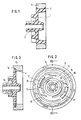
- a carrier part 1 is made of plastic in one piece with an output pinion 2 made of a thermoplastic.
- This carrier part is glued along the line 4 in the region of its circumferential line with an annular permanent magnet 3 made of barium ferrite material. This adhesive bond is sufficient with approximately the same coefficient of expansion of Ring magnet and carrier part at different temperatures.
- FIGS. 2 and 3 show the design of a rotor according to the invention, in which the bonding of the carrier part and the ring magnet in the case of temperature changes no longer leads to excessive stress on the bonding of the two components and thus to a partial tearing of the carrier part from the ring magnet. Such a partial tearing would impair the concentricity of the rotor and lead to noise during running, in the worst case to failure of the motor.
- FIGS. 2 and 3 denotes the carrier part made of a thermoplastic, which is produced in one piece with an output pinion 12.
- a ring magnet 13 made of permanent magnetic material is provided on its circumference with magnetized magnetic poles, 12 north and south poles each. This ring magnet 13 is glued to the carrier part 11 along the line 14.
- the design is such that the carrier part is completely surrounded by adhesive in the region of its outer circumference and does not abut or rest on the ring magnet at any point.
- annular slots 15 and 16 are made on different concentric circles to the rotor center axis. These circular slits overlap each other in the radial direction, so that, seen from the rotor center axis, there is no continuous material connection to the ring magnet.
Landscapes
- Engineering & Computer Science (AREA)
- Power Engineering (AREA)
- Permanent Field Magnets Of Synchronous Machinery (AREA)
Description
- Die Erfindung bezieht sich auf einen Rotor für Elektro-Kleinmotoren mit einem Ringmagnet aus permanentmagnetischem Material mit aufmagnetisierten Magnetpolen und einem Trägerteil aus Kunststoff, welches mit dem Ringmagnet verklebt ist und diesen mit einem Abtriebsritzel auf der Rotormittelachse verbindet. Siehe DE-U-6947050. Elektro-Kleinmotoren mit einem Rotor der eingangs genannten Art bringt die Anmelderin seit Jahren in großen Stückzahlen auf den Markt. Bei diesen Rotoren, siehe Fig. 1 der Zeichnung, ist das Trägerteil aus Kunststoff mit dem Ringmagneten an dessen Innenumfang über die volle Breite verklebt. Eine derartige Verklebung ist haltbar, solange der Ausdehnungskoeffizient des Magnetmaterials und des Kunststoffs der Trägeroplatte bei höheren Temperaturen sowie beim Abkühlen nach dem Spritzvorgang des Trägerteils in etwa gleich sind. Bei der Verwendung eines neuen Magnetmaterials aus Sinterkeramik ist jedoch die bisherige Ausbildung von Trägerteil und Ringmagnet wegen der unterschiedlichen Ausdehnungskoeffizienten beider Materialien nicht mehr möglich. Es käme zum Reißen des Kunststoffträgerteils vom Ringmagnet nach dem Abkühlen vom Spritzvorgang.
- Es ist Aufgabe der Erfindung, eine Ausgestaltung des Rotors aufzuzeigen, bei welcher die unterschiedlichen Ausdehnungskoeffizienten der Materialien von Trägerteil und Ringmagnet keinen Einfluß auf die Klebeverbindung zwischen beiden Bauteilen hat.
- Gemäß der Erfindung wird daher vorgeschlagen, daß das Trägerteil Aussparungen aufweist, derart, daß zwischen dem Abtriebsritzel und dem Ringmagnet keine radial durchgängige Materialverbindung besteht.
- Durch diese Ausbildung erhält das Trägerteil in sich in begrenztem Maße ein federndes Verhalten und kann somit ohne besondere Beanspruchung der Klebestellen unterschiedliche Materialausdehnungen von Trägerteil und Ringmagnet ausgleichen.
- In bevorzugter Weiterbildung der Erfindung ist vorgesehen, daß die Aussparungen als kreisringförmige Schlitze ausgebildet sind, welche konzentrisch und in Drehrichtung des Rotors gegeneinander versetzt auf dem Trägerteil angebracht sind.
- Noch weitere Ausbildungen der Erfindung sind in den Unteransprüchen erläutert.
- Im folgenden soll die Erfindung anhand der Zeichnung an einem Ausführungsbeispiel erläutert werden.
-
- Fig. 1
- einen Rotor im Schnitt entsprechend dem Stand der Technik,
- Fig. 2
- einen Rotor gemäß der Erfindung in Draufsicht,
- Fig. 3
- einen Rotor nach Fig. 2 im Schnitt entlang der Schnittlinie III-III.
- Bei dem bekannten Rotor ist ein Trägerteil 1 aus Kunststoff einstückig mit einem Abtriebsritzel 2 aus einem thermoplastischen Kunststoff hergestellt. Dieses Trägerteil ist im Bereich seiner Umfangslinie mit einem ringförmigen Permanentmagneten 3 aus Bariumferrit-Material entlang der Linie 4 verklebt. Diese Klebeverbindung ist ausreichend bei etwa gleichem Ausdehnungskoeffizienten von Ringmagnet und Trägerteil bei verschiedenen Temperaturen.
- In den Figuren 2 und 3 ist die Ausgestaltung eines Rotors entsprechend der Erfindung dargestellt, bei welcher die Verklebung von Trägerteil und Ringmagnet bei Temperaturänderungen nicht mehr zu einer übermäßigen Beanspruchung der Verklebung beider Bauteile und damit zu einem partiellen Abreißen des Trägerteils von dem Ringmagneten führt. Ein solches partielles Abreißen würde den Rundlauf des Rotors beeinträchtigen und zu einer Geräuschentwicklung beim Lauf, im ungünstigsten Falle zu einem Ausfall des Motors führen.
- Mit 11 ist in den Figuren 2 und 3 das Trägerteil aus einem thermoplastischen Kunststoff bezeichnet, welches einstückig mit einem Abtriebsritzel 12 hergestellt wird. Ein Ringmagnet 13 aus permanentmagnetischem Material ist an seinem Umfang mit aufmagnetisierten Magnetpolen, je 12 Nord- und Südpolen, versehen. Dieser Ringmagnet 13 ist entlang der Linie 14 mit dem Trägerteil 11 verklebt. Die Ausbildung ist dabei so getroffen, daß das Trägerteil im Bereich seines Außenumfanges voll mit Klebstoff umgeben ist und an keiner Stelle an dem Ringmagneten an- oder aufliegt. In dem Trägerteil 11 sind kreisringförmige Schlitze 15 und 16 auf verschiedenen konzentrischen Kreisen zur Rotormittelachse angebracht. Diese kreisringförmigen Schlitze überdecken einander in radialer Richtung, so daß von der Rotormittelachse aus gesehen keine durchgängige Materialverbindung zu dem Ringmagneten besteht.
- Es ist im Sinne der Erfindung natürlich auch möglich, die Aussparungen in geometrisch anderer Art auszugestalten. Wesentlich dabei ist nur, daß die Aussparungen ein ausreichendes federndes Verhalten des Trägerteils 11 ermöglichen und daß dieses federnde Verhalten nicht durch durchgängige, radiale Materialstege zwischen Abtriebsritzel und Ringmagnet gestört wird.
- Mit 17 sind Nocken bezeichnet, welche im Zusammenwirken mit einem nicht dargestellten Hebel eine Rücklaufsperre bilden. Mit 18 sind schließlich Schlitze im Trägerteil 11 bezeichnet, welche sich beim Klebevorgang mit Klebstoff füllen und eine bessere Verbindung zwischen Trägerteil 11 und Ringmagneten gewährleisten.
Claims (4)
- Rotor für Elektro-Kleinmotoren mit einem Ringmagnet (13) aus permanentmagnetischem Material mit aufmagnetisierten Magnetpolen (12) und einem Trägerteil (11) aus Kunststoff, welches mit dem Ringmagnet (13) verklebt ist und diesen mit einem Abtriebsritzel (12) auf der Rotormittelachse verbindet,
dadurch gekennzeichnet,
daß das Trägerteil (11) Aussparungen (15, 16) aufweist, derart, daß zwischen dem Abtriebsritzel (12) und dem Ringmagnet (13) keine radial durchgängige Materialverbindung besteht. - Rotor nach Anspruch 1,
dadurch gekennzeichnet,
daß die Aussparungen (15, 16) als kreisringförmige Schlitze ausgebildet sind, welche konzentrisch und in Drehrichtung des Rotors gegeneinander versetzt auf dem Trägerteil (11) angebracht sind. - Rotor nach Anspruch 1 oder 2,
dadurch gekennzeichnet,
daß das Trägerteil (11) an seinem Umfang im Bereich der Verklebung (14) mit dem Ringmagneten (13) radiale Ausnehmungen (18) aufweist. - Rotor nach Anspruch 1,
dadurch gekennzeichnet,
daß Trägerteil (11 ) und Abtriebsritzel (12) einstückig aus thermoplastischem Kunststoff hergestellt sind.
Applications Claiming Priority (2)
| Application Number | Priority Date | Filing Date | Title |
|---|---|---|---|
| DE8526565U | 1985-09-17 | ||
| DE8526565U DE8526565U1 (de) | 1985-09-17 | 1985-09-17 |
Publications (3)
| Publication Number | Publication Date |
|---|---|
| EP0215450A2 EP0215450A2 (de) | 1987-03-25 |
| EP0215450A3 EP0215450A3 (en) | 1988-03-30 |
| EP0215450B1 true EP0215450B1 (de) | 1991-04-10 |
Family
ID=6785350
Family Applications (1)
| Application Number | Title | Priority Date | Filing Date |
|---|---|---|---|
| EP86112621A Expired - Lifetime EP0215450B1 (de) | 1985-09-17 | 1986-09-12 | Rotor für Elektro-Kleinmotoren |
Country Status (4)
| Country | Link |
|---|---|
| EP (1) | EP0215450B1 (de) |
| DE (2) | DE8526565U1 (de) |
| HK (1) | HK97891A (de) |
| SG (1) | SG94191G (de) |
Families Citing this family (4)
| Publication number | Priority date | Publication date | Assignee | Title |
|---|---|---|---|---|
| JPH0638414A (ja) * | 1992-07-14 | 1994-02-10 | Daido Steel Co Ltd | リング状磁石をそなえたロータ |
| JP2001327105A (ja) * | 2000-05-17 | 2001-11-22 | Fujitsu General Ltd | 電動機の回転子およびその製造方法 |
| DE102007029738A1 (de) * | 2007-06-27 | 2009-01-08 | Robert Bosch Gmbh | Rotor für einen Elektromotor und Elektrowerkzeugmaschine mit einem Elektromotor und einem Rotor |
| WO2017133784A1 (en) * | 2016-02-05 | 2017-08-10 | Arcelik Anonim Sirketi | Interior permanent-magnet rotor of a brushless motor |
Family Cites Families (3)
| Publication number | Priority date | Publication date | Assignee | Title |
|---|---|---|---|---|
| DE6947050U (de) * | 1969-12-04 | 1970-05-06 | Diehl Fa | Permanentmagnetischer rotor. |
| US4472650A (en) * | 1982-02-11 | 1984-09-18 | Advolotkin Nikolai P | Rotor of high-speed electric machine |
| AT376849B (de) * | 1982-09-15 | 1985-01-10 | Philips Nv | Elektromotor |
-
1985
- 1985-09-17 DE DE8526565U patent/DE8526565U1/de not_active Expired
-
1986
- 1986-09-12 DE DE8686112621T patent/DE3678654D1/de not_active Expired - Fee Related
- 1986-09-12 EP EP86112621A patent/EP0215450B1/de not_active Expired - Lifetime
-
1991
- 1991-11-07 SG SG941/91A patent/SG94191G/en unknown
- 1991-12-05 HK HK978/91A patent/HK97891A/xx not_active IP Right Cessation
Also Published As
| Publication number | Publication date |
|---|---|
| SG94191G (en) | 1991-12-13 |
| DE3678654D1 (de) | 1991-05-16 |
| EP0215450A3 (en) | 1988-03-30 |
| EP0215450A2 (de) | 1987-03-25 |
| HK97891A (en) | 1991-12-13 |
| DE8526565U1 (de) | 1987-01-22 |
Similar Documents
| Publication | Publication Date | Title |
|---|---|---|
| DE2556631C2 (de) | Elektrische Motorpumpe | |
| EP0980081B1 (de) | Hochgefülltes Kunststoffteil | |
| DE2053262B2 (de) | Wechselspannungsgenerator zur Drehzahlmessung, insbesondere für eine Blockierschutzeinrichtung einer Fahrzeugbremsanlage | |
| EP1855372B1 (de) | Glockenankerspule | |
| DE102004017507A1 (de) | Rotoranordnung für eine elektrische Maschine | |
| DE2653799C3 (de) | Triggerimpulsgenerator zum Erzeugen zeitlich beabstandeter Zündsteuersignale, sowie Gerät und Verfahren zur Magnetisierung des Generators | |
| EP0812050B1 (de) | Elektromotor | |
| DE3502899C2 (de) | ||
| EP0215450B1 (de) | Rotor für Elektro-Kleinmotoren | |
| EP0902880A1 (de) | Magnetring | |
| EP0190297B1 (de) | Axial kompakter direktantriebsmotor | |
| DE3308946C2 (de) | ||
| DE3044576A1 (de) | Rotoranordnung, insbesondere fuer schrittschaltmotoren | |
| DE2360214A1 (de) | Elektrischer mikromotor mit schrittweiser drehung | |
| DE2848259A1 (de) | Schwingspulenmotor | |
| DE19800570B4 (de) | Gebläse mit einem Lüfterrad | |
| EP0307663B1 (de) | Kollektormotor zum Antrieb von Hausgeräten, insbesondere Waschmaschinen | |
| EP2048769B1 (de) | Reluktanzmotor | |
| DE3031273A1 (de) | Elektromagnetische vorrichtung. | |
| DE1907137A1 (de) | Polarisierter Synchron-Kleinstmotor | |
| DE3628961C1 (en) | Model rail-mounted vehicle | |
| DE102016101437A1 (de) | Rotor für einen Elektromotor eines elektrischen Verdichters | |
| AT311484B (de) | Wechselspannungsgenerator zur Drehzahlmessung, insbesondere für eine Blockierschutzeinrichtung einer Fahrzeugbremsanlage | |
| DE2934183A1 (de) | Elektromotor mit einem flachen luftspalt | |
| DE187740T1 (de) | Einphasiger motor mit einem magnetisierten laeufer. |
Legal Events
| Date | Code | Title | Description |
|---|---|---|---|
| PUAI | Public reference made under article 153(3) epc to a published international application that has entered the european phase |
Free format text: ORIGINAL CODE: 0009012 |
|
| AK | Designated contracting states |
Kind code of ref document: A2 Designated state(s): DE FR GB IT |
|
| PUAL | Search report despatched |
Free format text: ORIGINAL CODE: 0009013 |
|
| AK | Designated contracting states |
Kind code of ref document: A3 Designated state(s): DE FR GB IT |
|
| 17P | Request for examination filed |
Effective date: 19880216 |
|
| 17Q | First examination report despatched |
Effective date: 19900921 |
|
| GRAA | (expected) grant |
Free format text: ORIGINAL CODE: 0009210 |
|
| AK | Designated contracting states |
Kind code of ref document: B1 Designated state(s): DE FR GB IT |
|
| REF | Corresponds to: |
Ref document number: 3678654 Country of ref document: DE Date of ref document: 19910516 |
|
| ITF | It: translation for a ep patent filed |
Owner name: STUDIO JAUMANN |
|
| ET | Fr: translation filed | ||
| GBT | Gb: translation of ep patent filed (gb section 77(6)(a)/1977) | ||
| PLBE | No opposition filed within time limit |
Free format text: ORIGINAL CODE: 0009261 |
|
| STAA | Information on the status of an ep patent application or granted ep patent |
Free format text: STATUS: NO OPPOSITION FILED WITHIN TIME LIMIT |
|
| 26N | No opposition filed | ||
| PGFP | Annual fee paid to national office [announced via postgrant information from national office to epo] |
Ref country code: GB Payment date: 19970908 Year of fee payment: 12 |
|
| PGFP | Annual fee paid to national office [announced via postgrant information from national office to epo] |
Ref country code: FR Payment date: 19970929 Year of fee payment: 12 |
|
| PGFP | Annual fee paid to national office [announced via postgrant information from national office to epo] |
Ref country code: DE Payment date: 19971118 Year of fee payment: 12 |
|
| PG25 | Lapsed in a contracting state [announced via postgrant information from national office to epo] |
Ref country code: GB Free format text: LAPSE BECAUSE OF NON-PAYMENT OF DUE FEES Effective date: 19980912 |
|
| GBPC | Gb: european patent ceased through non-payment of renewal fee |
Effective date: 19980912 |
|
| PG25 | Lapsed in a contracting state [announced via postgrant information from national office to epo] |
Ref country code: FR Free format text: LAPSE BECAUSE OF NON-PAYMENT OF DUE FEES Effective date: 19990531 |
|
| PG25 | Lapsed in a contracting state [announced via postgrant information from national office to epo] |
Ref country code: DE Free format text: LAPSE BECAUSE OF NON-PAYMENT OF DUE FEES Effective date: 19990701 |
|
| REG | Reference to a national code |
Ref country code: FR Ref legal event code: ST |
|
| PG25 | Lapsed in a contracting state [announced via postgrant information from national office to epo] |
Ref country code: IT Free format text: LAPSE BECAUSE OF NON-PAYMENT OF DUE FEES;WARNING: LAPSES OF ITALIAN PATENTS WITH EFFECTIVE DATE BEFORE 2007 MAY HAVE OCCURRED AT ANY TIME BEFORE 2007. THE CORRECT EFFECTIVE DATE MAY BE DIFFERENT FROM THE ONE RECORDED. Effective date: 20050912 |