EP0215411B1 - Automatisches Steuerungssystem der Gemischzusammensetzung im Leerlauf eines Brennkraftmotors mit einem elektronischen Kraftstoffeinspritzungssystem ausgerüstet - Google Patents
Automatisches Steuerungssystem der Gemischzusammensetzung im Leerlauf eines Brennkraftmotors mit einem elektronischen Kraftstoffeinspritzungssystem ausgerüstet Download PDFInfo
- Publication number
- EP0215411B1 EP0215411B1 EP86112395A EP86112395A EP0215411B1 EP 0215411 B1 EP0215411 B1 EP 0215411B1 EP 86112395 A EP86112395 A EP 86112395A EP 86112395 A EP86112395 A EP 86112395A EP 0215411 B1 EP0215411 B1 EP 0215411B1
- Authority
- EP
- European Patent Office
- Prior art keywords
- engine
- air
- speed
- rotation
- fact
- Prior art date
- Legal status (The legal status is an assumption and is not a legal conclusion. Google has not performed a legal analysis and makes no representation as to the accuracy of the status listed.)
- Expired
Links
- 239000000446 fuel Substances 0.000 title claims description 33
- 239000000203 mixture Substances 0.000 title claims description 27
- 238000002347 injection Methods 0.000 title claims description 15
- 239000007924 injection Substances 0.000 title claims description 15
- 230000000737 periodic effect Effects 0.000 claims description 14
- 102100025477 GTP-binding protein Rit1 Human genes 0.000 claims description 6
- 102100027778 GTP-binding protein Rit2 Human genes 0.000 claims description 6
- 101000574654 Homo sapiens GTP-binding protein Rit1 Proteins 0.000 claims description 6
- 101000725879 Homo sapiens GTP-binding protein Rit2 Proteins 0.000 claims description 6
- 238000002485 combustion reaction Methods 0.000 claims description 4
- 239000000498 cooling water Substances 0.000 claims description 3
- 230000000694 effects Effects 0.000 claims description 3
- 230000033228 biological regulation Effects 0.000 claims description 2
- 230000004913 activation Effects 0.000 claims 1
- 230000006698 induction Effects 0.000 description 6
- 101100204393 Arabidopsis thaliana SUMO2 gene Proteins 0.000 description 4
- 101150112492 SUM-1 gene Proteins 0.000 description 4
- 101150096255 SUMO1 gene Proteins 0.000 description 4
- 101100311460 Schizosaccharomyces pombe (strain 972 / ATCC 24843) sum2 gene Proteins 0.000 description 4
- 230000006870 function Effects 0.000 description 4
- 238000006073 displacement reaction Methods 0.000 description 3
- 238000013507 mapping Methods 0.000 description 3
- 238000001514 detection method Methods 0.000 description 2
- 238000009826 distribution Methods 0.000 description 2
- 238000005259 measurement Methods 0.000 description 2
- 238000011144 upstream manufacturing Methods 0.000 description 2
- -1 CNTCC1 Proteins 0.000 description 1
- 230000032683 aging Effects 0.000 description 1
- 230000006835 compression Effects 0.000 description 1
- 238000007906 compression Methods 0.000 description 1
- 238000011217 control strategy Methods 0.000 description 1
- 238000001816 cooling Methods 0.000 description 1
- 238000012937 correction Methods 0.000 description 1
- 230000015654 memory Effects 0.000 description 1
- 238000000034 method Methods 0.000 description 1
- 238000012986 modification Methods 0.000 description 1
- 230000004048 modification Effects 0.000 description 1
- 230000003252 repetitive effect Effects 0.000 description 1
- XLYOFNOQVPJJNP-UHFFFAOYSA-N water Substances O XLYOFNOQVPJJNP-UHFFFAOYSA-N 0.000 description 1
Images
Classifications
-
- F—MECHANICAL ENGINEERING; LIGHTING; HEATING; WEAPONS; BLASTING
- F02—COMBUSTION ENGINES; HOT-GAS OR COMBUSTION-PRODUCT ENGINE PLANTS
- F02D—CONTROLLING COMBUSTION ENGINES
- F02D43/00—Conjoint electrical control of two or more functions, e.g. ignition, fuel-air mixture, recirculation, supercharging or exhaust-gas treatment
-
- F—MECHANICAL ENGINEERING; LIGHTING; HEATING; WEAPONS; BLASTING
- F02—COMBUSTION ENGINES; HOT-GAS OR COMBUSTION-PRODUCT ENGINE PLANTS
- F02D—CONTROLLING COMBUSTION ENGINES
- F02D41/00—Electrical control of supply of combustible mixture or its constituents
- F02D41/02—Circuit arrangements for generating control signals
- F02D41/14—Introducing closed-loop corrections
- F02D41/1401—Introducing closed-loop corrections characterised by the control or regulation method
- F02D41/1408—Dithering techniques
Definitions
- the present invention relates to an automatic system for control of the mixture strength supplied in slow-running conditions to a heat engine having an electronic fuel injection system, in particular a sequential and phased system, and including a valve for supply of supplementary air in adjustable quantities, generally disposed to divide a duct connecting zones upstream and downstream of the butterfly valve controlled by the accelerator.
- drift of the petrol/air mixture strength with which a heat engine is supplied is a rather typical phenomenon so much so that periodic adjustment has to be made to the supply system both in new systems and during its lifetime, following ageing of the engine and drift of its components.
- Such drift of the mixture strength is particularly unwanted in the case of electronic injection systems which due to their better operation necessitate very precise general control strategies of operation of the engine, in that there exists an electronic central control unit which, in dependence on signals which it receives from various sensors (principally sensors detecting the speed of rotation and phases of the engine, and sensors detecting the pressure and temperature of the inducted air) determines for example the density of the air in the manifold and the speed of rotation of the engine, from which, in dependence on the desired mixture strength it calculates through an interpolation on respective memorised mappings a phase and duration of injection of the fuel at the injectors as well as the ignition advance.
- the said calculating means include counter means having two predetermined count windows in which the speed of rotation of the engine is detected, and means calculating the difference between the mean speeds in the said count windows and means adjusting the fuel injection amount according to said difference, and delay means delaying by a delay window the first count window after a change in the air quantity.
- the object of the present invention is that of providing a performed automatic control system for controlling the fuel mixture strength supplied particularly in slow running conditions, so as to maintain it in the desired tolerance range.
- an automatic control system adjusting the strength of the fuel mixture supplied, in slow running conditions, to an internal combustion engine having an electronic fuel injection system and comprising first means periodically varying a quantity of supplementary air supplied to the engine and detecting the consequent variation in the speed of the said engine, the said first means including means causing, by a supplementary air supply means, a periodic increase and decrease in the quantity of the said air about a mean value, and means calculating the corresponding variation in the speed of rotation of the engine as a direct consequence of the said increase and decrease in the supplementary air, and detecting if the said increase or decrease of air corresponds to an increase or decrease of the said speed of rotation or vice versa, the said calculating means include counter means having two predetermined count windows in which the speed of rotation of the engine is detected, and means calculating the difference between the mean speeds in the said count windows and means adjusting the fuel injection amount according to said difference, and delay means delaying by a delay window the first count window after a change in the air quantity, characterised by the delay window having
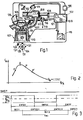
- an electronic injection system for a heat engine 101 conveniently a four-cylinder engine which is only partially shown in section.
- This system includes an electronic central control unit 102 including, in a substantially known way, a microprocessor 121 and registers in which there are memorised mappings relating to different operating conditions of the engine 101, as well as various counters and random access memory registers (RAM).
- a microprocessor 121 and registers in which there are memorised mappings relating to different operating conditions of the engine 101, as well as various counters and random access memory registers (RAM).
- RAM random access memory registers
- This central control unit 102 receives signals from:
- This electronic central control unit 102 is connected to an electrical supply battery 115 and to earth, and, in dependence on the signals from the said sensors, the speed of rotation of the engine and the density of the air are utilised to determine the quantity of fuel in dependence on the desired mixture strength.
- This central control unit 102 therefore controls the duration of opening of the electro-injectors 116 disposed in the manifold 107 close to the induction valve of each respective cylinder, to meter the quantity of fuel provided to the different cylinders of the engine 101 and to control the phasing of the injection to determine the commencement of fuel delivery with respect to the phases (induction, compression, expansion, exhaust) of the engine 101.
- Each electro-injector 116 is supplied with fuel through a pressure regulator 117 sensitive to the pressure in the induction manifold 107 and having a fuel inlet duct 118 for fuel coming from a pump (not illustrated), and a return duct 119 leading to a reservoir (not illustrated).
- This electronic central control unit 102 is moreover connected to a unit 120 for control of the ignition pulses which are provided to the various cylinders through the distributor 126, and controls the valve 114 for controlling the supply of supplementary air in a manner which will be described in more detail hereinbelow, according to the characteristics of the present invention, the principle of operation of which is summarised with reference to Figure 2 which is a graph on which are plotted, along the abscissa, the values of the mixture strength, that is to say the ratio of the quantity of fuel injected to the quantity of air supplied, whilst along the ordinate are plotted the values of engine torque which are proportional to the speed of rotation of the engine.
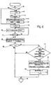
- the programme of the electronic injection system controlled by the microprocessor 121 starts each cycle at a stage 10 at which it is detected whether this is the first time this part of the programme for automatic control of the fuel mixture strength in slow running conditions is being performed: in the positive case the programme passed to stage 11 at which the index i is set to 0, and the programme then passes to a stage 12 at which the periodic supply of the quantity of supplementary air Q A is controlled about a mean value via the electromagnetic valve 114, and inverted at each period CNTCC determined by a counter of the central control unit 102 which is started at a predetermined value and decremented by signals SMOT coming, as can be seen in Figure 3, from the sensor 103 at each 90 ° of rotation of the engine crankshaft 125 ( Figure 1); upon zeroing of this counter CNTCC the control signal to the valve 114 is modified so as to invert the sign of the variation of quantity of additional air with respect to the mean-value, and the initial value of the counter is renewed for the decremental count which determines the new period CNT
- This period CNTCC, and the variation Q A of the additional air, equal to about 4% of the air supplied through the butterfly valve 112 in the slow running conditions, is such as to cause variations in the drive torque which are distinguishable from perturbations which can arise in the engine due to poor stability of the speed of rotation due to other causes.
- This period CNTCC, and the variation Q A of the additional air, equal to about 4% of the air supplied through the butterfly valve 112 in the slow running conditions, is such as to cause variations in the drive torque which are distinguishable from perturbations which can arise in the engine due to poor stability of the speed of rotation due to other causes.
- stage 13 determines via one or more counters the count of respective successive periods, illustrated in Figure 3 and indicated with RIT1, CNTCC1, RIT2, CNTCC2, CNTCC1,...Such periods are determined by the decremental count down to zero of a respective counter starting from a predetermined value, and for which there are provided as clock signals the same signal SMOT from the sensor 103 also provided to the counter for determining the period CNTCC as already described.
- the periods CNTCC1 and CNTCC2 have the function of determining the detection window through which the perturbations of the speed of rotation caused by the introduction of supplementary air Q A with the respective increase and decrease with respect to the mean value are determined, whilst the period RIT1 has the function of determining an adequate detection delay with respect to the commencement of the modification of the additional air to take account of the intrinsic delay of the supply and distribution system of the engine, whilst the period RIT2 has the function of taking account of this intrinsic delay in the variations in the sign of the additional air Q A with respect to the mean values.
- the period RIT1 is equal to about half the duration of the period CNTCC
- the period RIT2 is of substantially negligible duration
- the periods CNTCC1 and CNTCC2 are of substantially the same duration, equal to that of the period CNTCC of application, with constant sign, of the quantity Q of the additional air.
- stage 14 which calculates the memories indicated respectively SUM1 and SUM2 the sum of the time intervals between the various signals SMOT in the respective acquisition windows CNTCC1 and CNTCC2 corresponding to the mean speed of rotation in these windows.
- stage 15 is a stage 16 at which is calculated, in a register DIFFSUM, the difference between the values in the registers SUM1 and SUM2, that is to say the difference between the mean speeds of rotation in the windows CNTCC1 and CNTCC2 are detected; it must also be noted that since these windows can have different basic durations determined by a different count of signals SMOT, the value calculated in the register SUM1 and SUM2 at stage 14 can be altered to normalise it and make it refer to the same signal count SMOT in the two windows.
- stage 16 there is a stage 17 which detects if the count window of period CNTCC2 is concluded, that is to say if the associated counter has reached zero: in the negative case it returns to stage 16, whilst in the positive case it passes to a stage 18 which puts the value SUMMOD into an associated register equal to the previously memorised value (SUMMOD) to which is added the value DIFFSUM determined at stage 16; at stage 18 the registers SUM1 and SUM2 are then returned to zero.
- stage 17 which detects if the count window of period CNTCC2 is concluded, that is to say if the associated counter has reached zero: in the negative case it returns to stage 16, whilst in the positive case it passes to a stage 18 which puts the value SUMMOD into an associated register equal to the previously memorised value (SUMMOD) to which is added the value DIFFSUM determined at stage 16; at stage 18 the registers SUM1 and SUM2 are then returned to zero.
- SUMMOD previously memorised value
- the programme then leads to a stage 20 which determines if the index i is equal to N (for example 20) to detect if this modulation cycle of additional air and measurement of the variation of the speed of rotation of the engine 101 indicated Tmi ( Figure 3) has been repeated for a sufficient number of times, established by N.
- N for example 20
- stage 21 which detects if the temperature of the engine cooling water detected by the sensor 110 is greater than a predetermined value (T i ), if the speed of rotation of the engine is greater than a predetermined threshold value (RPMO), if the butterfly valve 112 (FARF) is in the minimum position (FARFMIN) and if the value (SUMMOD) of the difference in the speed of rotation between the positive and negative increments of the additional air via the valve 114, repeated for the predetermined number of cycles N is, in absolute value, greater than a threshold value So, which is indicative of a displacement of the speed of rotation of the engine, and therefore of the mixture strength, at slow running of the engine, greater than the admissible range of variation.
- T i a predetermined value
- RPMO predetermined threshold value
- FARFMIN butterfly valve 112
- SUMMOD value of the difference in the speed of rotation between the positive and negative increments of the additional air via the valve 114, repeated for the predetermined number of cycles N is, in absolute value, greater than a threshold
- stage 22 which evaluates if the value of the parameter SUMMOD is positive or negative; in the first case this is indicative of a displacement from the point P ( Figure 2) towards the point P", that is to say in the section of the. curve to the right of the point A, so that it is necessary to reduce the quantity of fuel injected to bring the point P" back towards the point P, and therefore the additional regulation time for disablement of the injector 116 is calculated in an incremented manner, that is to say equal to:
- stage 22 From the stage 22 the programme then passes to a stage 23 which puts the value SUMMOD in the respective registers equal to zero, and likewise zeros the index i to enable successive cycles of calculation of this automatic control system of the slow running mixture strength. After the stage 23 there is then a stage 25 which controls the subsequent operation of the programme through the microcomputer 121 for actuation of sequential and phased controls supplied to the electro injectors 116.
- the programme passes directly to this stage 25 in the case of negative conditions established at stage 20, that is to say if the repetitive cycles of modulation of the additional air and measurement of the variation of the speed of rotation of the engine have not been performed for the total desired number N of cycles, or in the case of negative conditions established by the stage 21, that is to say, if the temperature of the cooling water of the engine is relatively low, if the speed of rotation is low, if the butterfly valve 112 is not in its minimum position, or if the variation of the speed of rotation (SUMMOD) does not exceed the predetermined threshold value So, that is to say, if the variation of the mixture strength has not passed out of the desired range, which implies that the operating point is around the initially established point P of Figure 2.
Landscapes
- Engineering & Computer Science (AREA)
- Chemical & Material Sciences (AREA)
- Combustion & Propulsion (AREA)
- Mechanical Engineering (AREA)
- General Engineering & Computer Science (AREA)
- Electrical Control Of Air Or Fuel Supplied To Internal-Combustion Engine (AREA)
Claims (9)
daß das Verzögerungsfenster (RIT1) etwa die halbe Dauer der periodischen Veränderungen (CNTCC) der Zusatzluft aufweist und daß die Zählfenster (CNTCC1, CNTCC2) eine Dauer der gleichen Größenordnung aufweisen, die im wesentlichen gleich der (CNTCC) der periodischen Veränderungen in der Zusatzluft ist.
daß die Einrichtung für die Zufuhr von Zusatzluft ein elektromagnetisch gesteuertes Ventil (114) aufweist, das parallel zu einer Klappe (112) angeordnet ist, die durch das Gaspedal (113) gesteuert wird.
Applications Claiming Priority (2)
| Application Number | Priority Date | Filing Date | Title |
|---|---|---|---|
| IT67801/85A IT1182558B (it) | 1985-09-20 | 1985-09-20 | Sistema di controllo automatico in condizioni di regime di rotazione minimo del tipo della miscela combustibile adotta ad un motore endotermico comorendente un sistema di iniezione elettronica |
| IT6780185 | 1985-09-20 |
Publications (3)
| Publication Number | Publication Date |
|---|---|
| EP0215411A2 EP0215411A2 (de) | 1987-03-25 |
| EP0215411A3 EP0215411A3 (en) | 1987-11-04 |
| EP0215411B1 true EP0215411B1 (de) | 1990-02-07 |
Family
ID=11305393
Family Applications (1)
| Application Number | Title | Priority Date | Filing Date |
|---|---|---|---|
| EP86112395A Expired EP0215411B1 (de) | 1985-09-20 | 1986-09-08 | Automatisches Steuerungssystem der Gemischzusammensetzung im Leerlauf eines Brennkraftmotors mit einem elektronischen Kraftstoffeinspritzungssystem ausgerüstet |
Country Status (6)
| Country | Link |
|---|---|
| US (1) | US4847771A (de) |
| EP (1) | EP0215411B1 (de) |
| BR (1) | BR8604595A (de) |
| DE (1) | DE3668945D1 (de) |
| ES (1) | ES2002183A6 (de) |
| IT (1) | IT1182558B (de) |
Families Citing this family (11)
| Publication number | Priority date | Publication date | Assignee | Title |
|---|---|---|---|---|
| USRE40150E1 (en) | 1994-04-25 | 2008-03-11 | Matsushita Electric Industrial Co., Ltd. | Fiber optic module |
| US5546281A (en) | 1995-01-13 | 1996-08-13 | Methode Electronics, Inc. | Removable optoelectronic transceiver module with potting box |
| US5717533A (en) | 1995-01-13 | 1998-02-10 | Methode Electronics Inc. | Removable optoelectronic module |
| US6220878B1 (en) | 1995-10-04 | 2001-04-24 | Methode Electronics, Inc. | Optoelectronic module with grounding means |
| FR2739141B1 (fr) * | 1995-09-27 | 1997-12-05 | Siemens Automotive Sa | Procede de determination de la richesse optimale d'un melange air / carburant alimentant un moteur a combustion interne et dispositif correspondant |
| US5937826A (en) * | 1998-03-02 | 1999-08-17 | Cummins Engine Company, Inc. | Apparatus for controlling a fuel system of an internal combustion engine |
| US6203333B1 (en) | 1998-04-22 | 2001-03-20 | Stratos Lightwave, Inc. | High speed interface converter module |
| US6179627B1 (en) | 1998-04-22 | 2001-01-30 | Stratos Lightwave, Inc. | High speed interface converter module |
| US6220873B1 (en) | 1999-08-10 | 2001-04-24 | Stratos Lightwave, Inc. | Modified contact traces for interface converter |
| US6725147B2 (en) * | 2001-10-31 | 2004-04-20 | International Engine Intellectual Property Company, Llc | System and method for predicting quantity of injected fuel and adaptation to engine control system |
| AT516532B1 (de) * | 2014-11-24 | 2019-10-15 | Innio Jenbacher Gmbh & Co Og | Verfahren zum Starten einer mit einem Brennstoff-Luft-Gemisch betriebenen Brennkraftmaschine |
Family Cites Families (25)
| Publication number | Priority date | Publication date | Assignee | Title |
|---|---|---|---|---|
| FR2180182A5 (de) * | 1972-04-12 | 1973-11-23 | Sopromi Soc Proc Modern Inject | |
| DE2507055C2 (de) * | 1975-02-19 | 1984-11-22 | Robert Bosch Gmbh, 7000 Stuttgart | Verfahren (Optimierungsverfahren) und Vorrichtung zur Regelung einer Brennkraftmaschine |
| US3960320A (en) * | 1975-04-30 | 1976-06-01 | Forney Engineering Company | Combustion optimizer |
| DE2847021A1 (de) * | 1978-10-28 | 1980-05-14 | Bosch Gmbh Robert | Vorrichtung zur regelung von betriebskenngroessen einer brennkraftmaschine auf optimale werte |
| JPS5578138A (en) * | 1978-12-06 | 1980-06-12 | Nissan Motor Co Ltd | Idling speed control for internal combustion engine |
| JPS55160132A (en) * | 1979-05-31 | 1980-12-12 | Nissan Motor Co Ltd | Revolution controller of internal combustion engine |
| JPS5644431A (en) * | 1979-09-14 | 1981-04-23 | Nippon Denso Co Ltd | Method of controlling revolution speed of engine |
| JPS5751934A (en) * | 1980-09-16 | 1982-03-27 | Toyota Motor Corp | Idling revolution speed controller in internal combustion engine |
| JPS5759040A (en) * | 1980-09-26 | 1982-04-09 | Toyota Motor Corp | Intake air flow controlling process in internal combustion engine |
| JPS5770953A (en) * | 1980-10-22 | 1982-05-01 | Nippon Denso Co Ltd | Ignition timing control method |
| JPS57124051A (en) * | 1981-01-26 | 1982-08-02 | Nippon Denso Co Ltd | Optimum control method of internal combustion engine |
| JPS57203845A (en) * | 1981-06-08 | 1982-12-14 | Nippon Denso Co Ltd | Most suitable control device for internal-combustion engine |
| JPS58124041A (ja) * | 1982-01-19 | 1983-07-23 | Nippon Denso Co Ltd | 車両用空燃比制御装置 |
| JPS58176469A (ja) * | 1982-04-12 | 1983-10-15 | Nippon Soken Inc | 内燃機関の制御装置 |
| JPS58190530A (ja) * | 1982-04-20 | 1983-11-07 | Honda Motor Co Ltd | 内燃エンジンのアイドル回転数フィ−ドバック制御方法 |
| US4586473A (en) * | 1982-07-27 | 1986-05-06 | Equipements Automobiles Marshall | Method for the self-adaptive control of the angle of ignition advance of a thermal engine having positive ignition |
| DE3336028C3 (de) * | 1983-10-04 | 1997-04-03 | Bosch Gmbh Robert | Einrichtung zur Beeinflussung von Steuergrößen einer Brennkraftmaschine |
| US4703430A (en) * | 1983-11-21 | 1987-10-27 | Hitachi, Ltd. | Method controlling air-fuel ratio |
| DE3347664C2 (de) * | 1983-12-31 | 1987-01-29 | Dr. C. Otto & Co Gmbh, 4630 Bochum | Düsenblech-Konstruktion für Unterbrenner-Koksöfen |
| JPS6181546A (ja) * | 1984-09-28 | 1986-04-25 | Honda Motor Co Ltd | 内燃エンジンのアイドル回転数フイ−ドバツク制御方法 |
| JPH0612089B2 (ja) * | 1984-10-15 | 1994-02-16 | 本田技研工業株式会社 | 内燃エンジンのアイドル回転数フィードバック制御方法 |
| US4690121A (en) * | 1985-02-16 | 1987-09-01 | Honda Giken Kogyo Kabushiki Kaisha | Air intake side secondary air supply system for an internal combustion engine with a duty ratio control operation |
| JP2542568B2 (ja) * | 1985-04-02 | 1996-10-09 | 三菱電機株式会社 | 内燃機関の回転数制御装置 |
| JPH0647962B2 (ja) * | 1985-07-09 | 1994-06-22 | 日本電装株式会社 | 内燃機関のアイドル回転数制御装置 |
| JP2679970B2 (ja) * | 1985-10-21 | 1997-11-19 | 株式会社日立製作所 | アイドル回転速度制御装置 |
-
1985
- 1985-09-20 IT IT67801/85A patent/IT1182558B/it active
-
1986
- 1986-09-08 EP EP86112395A patent/EP0215411B1/de not_active Expired
- 1986-09-08 DE DE8686112395T patent/DE3668945D1/de not_active Expired - Lifetime
- 1986-09-12 US US06/907,309 patent/US4847771A/en not_active Expired - Fee Related
- 1986-09-19 ES ES8602047A patent/ES2002183A6/es not_active Expired
- 1986-09-19 BR BR8604595A patent/BR8604595A/pt not_active IP Right Cessation
Also Published As
| Publication number | Publication date |
|---|---|
| BR8604595A (pt) | 1987-05-26 |
| EP0215411A3 (en) | 1987-11-04 |
| DE3668945D1 (de) | 1990-03-15 |
| US4847771A (en) | 1989-07-11 |
| IT8567801A0 (it) | 1985-09-20 |
| EP0215411A2 (de) | 1987-03-25 |
| IT1182558B (it) | 1987-10-05 |
| ES2002183A6 (es) | 1988-07-16 |
Similar Documents
| Publication | Publication Date | Title |
|---|---|---|
| US4403584A (en) | Method and apparatus for optimum control for internal combustion engines | |
| US4676215A (en) | Method and apparatus for controlling the operating characteristic quantities of an internal combustion engine | |
| US6223730B1 (en) | Fuel injection control system of internal combustion engine | |
| US4886030A (en) | Method of and system for controlling fuel injection rate in an internal combustion engine | |
| US4561401A (en) | Air-fuel ratio control system | |
| US4442812A (en) | Method and apparatus for controlling internal combustion engines | |
| US5586537A (en) | Fuel property detecting apparatus for internal combustion engines | |
| US4448162A (en) | Optimum control for internal combustion engines | |
| US5806497A (en) | Method of and apparatus for controlling fuel injection of internal combustion engine | |
| US6644274B2 (en) | Apparatus for detecting a condition of burning in an internal combustion engine | |
| EP0215411B1 (de) | Automatisches Steuerungssystem der Gemischzusammensetzung im Leerlauf eines Brennkraftmotors mit einem elektronischen Kraftstoffeinspritzungssystem ausgerüstet | |
| JPH0823332B2 (ja) | 内燃機関の制御装置 | |
| US4674459A (en) | Apparatus for metering an air-fuel mixture to an internal combustion engine | |
| US4448171A (en) | Method and apparatus for optimum control of internal combustion engines | |
| US4457282A (en) | Electronic control for fuel injection | |
| US4475505A (en) | System for controlling idling rpm by synchronous control of supplementary air | |
| US5003955A (en) | Method of controlling air-fuel ratio | |
| US4800860A (en) | Fuel injection control system for internal combustion engine with precisely engine load dependent fuel injection amount adjustment feature | |
| US4977876A (en) | Fuel injection control system for internal combustion engine with fuel cut-off control at high engine speed range suppressive of recovery shock upon fuels resumption | |
| US4563994A (en) | Fuel injection control apparatus | |
| EP0215412B1 (de) | System zum Korrigieren der Kraftstoffeinspritzungsdauer, in Abhängigkeit von der Höhe für einen Brennkraftmotor mit einem elektronischen Einspritzungssystem | |
| EP0534506B1 (de) | System zur Steuerung des Luft/Kraftstoff-Verhältnisses für Brennkraftmotoren mit Steuerung der asynchronen Kraftstoffzuführung | |
| US4721086A (en) | System for controlling fuel injectors to open asynchronously with respect to the phases of a heat engine | |
| US4850326A (en) | Apparatus for learning and controlling air/fuel ratio in internal combustion engine | |
| US4787358A (en) | Fuel supply control system for an engine |
Legal Events
| Date | Code | Title | Description |
|---|---|---|---|
| PUAI | Public reference made under article 153(3) epc to a published international application that has entered the european phase |
Free format text: ORIGINAL CODE: 0009012 |
|
| AK | Designated contracting states |
Kind code of ref document: A2 Designated state(s): DE FR GB NL SE |
|
| PUAL | Search report despatched |
Free format text: ORIGINAL CODE: 0009013 |
|
| AK | Designated contracting states |
Kind code of ref document: A3 Designated state(s): DE FR GB NL SE |
|
| 17P | Request for examination filed |
Effective date: 19880429 |
|
| RAP1 | Party data changed (applicant data changed or rights of an application transferred) |
Owner name: WEBER S.R.L. |
|
| 17Q | First examination report despatched |
Effective date: 19880912 |
|
| GRAA | (expected) grant |
Free format text: ORIGINAL CODE: 0009210 |
|
| AK | Designated contracting states |
Kind code of ref document: B1 Designated state(s): DE FR GB NL SE |
|
| ET | Fr: translation filed | ||
| REF | Corresponds to: |
Ref document number: 3668945 Country of ref document: DE Date of ref document: 19900315 |
|
| PGFP | Annual fee paid to national office [announced via postgrant information from national office to epo] |
Ref country code: SE Payment date: 19900809 Year of fee payment: 5 |
|
| PGFP | Annual fee paid to national office [announced via postgrant information from national office to epo] |
Ref country code: NL Payment date: 19900930 Year of fee payment: 5 |
|
| PLBE | No opposition filed within time limit |
Free format text: ORIGINAL CODE: 0009261 |
|
| STAA | Information on the status of an ep patent application or granted ep patent |
Free format text: STATUS: NO OPPOSITION FILED WITHIN TIME LIMIT |
|
| 26N | No opposition filed | ||
| PG25 | Lapsed in a contracting state [announced via postgrant information from national office to epo] |
Ref country code: SE Effective date: 19910909 |
|
| PG25 | Lapsed in a contracting state [announced via postgrant information from national office to epo] |
Ref country code: NL Effective date: 19920401 |
|
| NLV4 | Nl: lapsed or anulled due to non-payment of the annual fee | ||
| EUG | Se: european patent has lapsed |
Ref document number: 86112395.8 Effective date: 19920408 |
|
| PGFP | Annual fee paid to national office [announced via postgrant information from national office to epo] |
Ref country code: FR Payment date: 20000829 Year of fee payment: 15 |
|
| PGFP | Annual fee paid to national office [announced via postgrant information from national office to epo] |
Ref country code: GB Payment date: 20000906 Year of fee payment: 15 |
|
| PGFP | Annual fee paid to national office [announced via postgrant information from national office to epo] |
Ref country code: DE Payment date: 20001128 Year of fee payment: 15 |
|
| PG25 | Lapsed in a contracting state [announced via postgrant information from national office to epo] |
Ref country code: GB Free format text: LAPSE BECAUSE OF NON-PAYMENT OF DUE FEES Effective date: 20010908 |
|
| GBPC | Gb: european patent ceased through non-payment of renewal fee |
Effective date: 20010908 |
|
| PG25 | Lapsed in a contracting state [announced via postgrant information from national office to epo] |
Ref country code: DE Free format text: LAPSE BECAUSE OF NON-PAYMENT OF DUE FEES Effective date: 20020501 |
|
| PG25 | Lapsed in a contracting state [announced via postgrant information from national office to epo] |
Ref country code: FR Free format text: LAPSE BECAUSE OF NON-PAYMENT OF DUE FEES Effective date: 20020531 |
|
| REG | Reference to a national code |
Ref country code: FR Ref legal event code: ST |