EP0215340A2 - Dispositif pour le transport de cahiers délivrés par une presse rotative - Google Patents
Dispositif pour le transport de cahiers délivrés par une presse rotative Download PDFInfo
- Publication number
- EP0215340A2 EP0215340A2 EP86111754A EP86111754A EP0215340A2 EP 0215340 A2 EP0215340 A2 EP 0215340A2 EP 86111754 A EP86111754 A EP 86111754A EP 86111754 A EP86111754 A EP 86111754A EP 0215340 A2 EP0215340 A2 EP 0215340A2
- Authority
- EP
- European Patent Office
- Prior art keywords
- helicoidal
- rollers
- path
- signatures
- conveying
- Prior art date
- Legal status (The legal status is an assumption and is not a legal conclusion. Google has not performed a legal analysis and makes no representation as to the accuracy of the status listed.)
- Withdrawn
Links
Images

Classifications
-
- B—PERFORMING OPERATIONS; TRANSPORTING
- B65—CONVEYING; PACKING; STORING; HANDLING THIN OR FILAMENTARY MATERIAL
- B65G—TRANSPORT OR STORAGE DEVICES, e.g. CONVEYORS FOR LOADING OR TIPPING, SHOP CONVEYOR SYSTEMS OR PNEUMATIC TUBE CONVEYORS
- B65G21/00—Supporting or protective framework or housings for endless load-carriers or traction elements of belt or chain conveyors
- B65G21/16—Supporting or protective framework or housings for endless load-carriers or traction elements of belt or chain conveyors for conveyors having endless load-carriers movable in curved paths
- B65G21/18—Supporting or protective framework or housings for endless load-carriers or traction elements of belt or chain conveyors for conveyors having endless load-carriers movable in curved paths in three-dimensionally curved paths
-
- B—PERFORMING OPERATIONS; TRANSPORTING
- B65—CONVEYING; PACKING; STORING; HANDLING THIN OR FILAMENTARY MATERIAL
- B65G—TRANSPORT OR STORAGE DEVICES, e.g. CONVEYORS FOR LOADING OR TIPPING, SHOP CONVEYOR SYSTEMS OR PNEUMATIC TUBE CONVEYORS
- B65G13/00—Roller-ways
- B65G13/11—Roller frames
-
- B—PERFORMING OPERATIONS; TRANSPORTING
- B65—CONVEYING; PACKING; STORING; HANDLING THIN OR FILAMENTARY MATERIAL
- B65G—TRANSPORT OR STORAGE DEVICES, e.g. CONVEYORS FOR LOADING OR TIPPING, SHOP CONVEYOR SYSTEMS OR PNEUMATIC TUBE CONVEYORS
- B65G2207/00—Indexing codes relating to constructional details, configuration and additional features of a handling device, e.g. Conveyors
- B65G2207/24—Helical or spiral conveying path
Definitions
- This invention relates to a device for conveying the signatures delivered by a rotary press.
- the signatures delivered by rotary presses as a continuous stream of overlapping units are normally conveyed, by means of a suitable device, towards different locations where said signatures undergo specific handling , e.g. stacking stations, distribution stations, and the like.
- Soundproofing, flameproofing, and safety regulations (such as those relating to the use of toluene, which is known to be harmful to health) require that the rotary presses be located in special facilities at some distance - up to 100 metres - from the rooms in which the signatures are gathered, stacked and handled, such distance depending, furthermore, on the shape and structure of the printing works' stores or buildings.
- these conveyors are normally designed as overhead units. Depending on the structure of the building or on the layout of the various handling stations, these conveyors develop along paths which often run across several floors of one and the same building, e.g. in modern buildings, one branch of said conveyors may be so designed as to lead directly to the area where the goods are loaded onto the distribution vehicles, generally at roadway level.
- These conventional conveyors consist, essentially, of a feeder unit moving along a guide bar and supporting a number of grippers (i.e. sprung clamping devices). Each gripper is designed to carry a signature.
- a further object of this invention is to provide a conveyor with rather limited overall dimensions even where rotary presses with two or more delivery ends are employed, as reduced size offers considerable advantages in terms of a more efficient use of the area available within the printing works.
- a conveying device comprising at least one vertical section developing along a spiral or helicoidal path, the signatures being conveyed as a continuous stream of overlapping units along said path.
- This design offers a considerable advantage in that it enables the signatures to dry thoroughly during conveyance without the use of grippers, which would lead to the damaging effects described earlier herein.
- the twisting vertical section designed to convey the signatures comprises a supporting column supplied with an outer jacket, said jacket carrying a number of adjacent feeder rollers, defining said spiral path, and with an internal axial shaft designed to drive said rollers, some shaft-driving units and transmission devices being interposed between said drive shaft and said feeder rollers.
- the design developed in accordance with this invention offers several advantages, including the following: - by defining the vertical conveyance section as a helicoidal path, namely a sequence of superelevated or parabolic curves, the scaled stream of signatures is carried continuously along the helicoidal path without forming any gaps in the stream itself - a defect commonly referred to as "splitting", namely a shift resulting in the formation of gaps in a stream of scaled signatures conveyed along a plane curve (e.g.
- a plan view of the device readily shows that the helicoidal path is circular in shape; this means that the tangential lines defining the rectilinear sections leading to and from the helicoidal path may be designed at will and in accordance with one's specific requirements, - two or more helicoidal paths may be fitted, like multi-start screws, onto one and the same column; this means that a single column may be used to carry several streams of signatures simultaneously delivered by the rotary press, - limited overall dimensions, - modular construction both of the column, which is achieved by employing as many modular column sectors as may be required at any given time, and of the conveying unit as a whole - that is, the conveyor track may be raised or lowered to meet specific requirements by simply using a column constructed to the same design, - the signatures are conveyed without suffering any damage whatsoever, as no pressure is exerted on them, - the ink
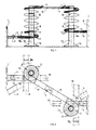
- number 1 refers to a rotary press, or a folding machine, featuring a conventional outlet section 2 delivering a stream 3 of signatures 4, in the form of newspapers, magazines, and the like, arranged in the conventional overlapping or scaled configuration.
- the inlet section of, e.g., a stacker 6 is indicated at 5.
- the conveying device according to the invention is marked, on the whole, with number 7, said device being placed between said outlet section 2 and inlet section 5.
- the conveyor consists, essentially, of an upward section 8, a downward section 9, and an intervening section 10.
- the vertical sections or tracks 8 and 9 follow a helicoidal path which, in this particular instance, is defined by a number of adjacent feeder rollers 11, on which the scaled stream 3 is conveyed, said stream of signatures running from outlet 2 to inlet 5 while retaining a scaled configuration.
- the two vertical sections 8 and 9 are structurally similar.
- Each vertical section comprises, essentially, a supporting column 12 provided with an outer jacket 13 carrying a number of the aforementioned feeder rollers 11.
- Jacket 13 houses an axial drive shaft 14, designed to operate said feeder rollers 11 by means of suitable transmission gears, which will be described in detail hereinafter.
- the shaft 14 is driven by a geared motor 15.
- the lower end of the shaft 14 is supported by the bedplate 16 of said column.
- the projecting rollers 11 are suitably supported by jacket 13, for instance by means of one or more conventional rolling bearings, and are cone-shaped. Said feeder rollers 11 are arranged side-by-side with one another so as to define a helicoidal path of the desired pitch, e.g. 40 cms.
- the driving units placed between the drive shaft 14 and said feeder rollers 11 comprise, in this particular example, a number of disks 17 integrally fitted onto the shaft 14, e.g. by means of keys (not shown in the figures), and evenly spaced out thereon.
- Each of said disks 17 is designed to engage a wheel 18 placed at the end of a small oscillating shaft 19, which is in turn supported by the jacket 13 of the column 12, its other end 20 projecting therefrom.
- Said oscillatory connection which may be effected by means of conventional rolling bearings, is schematically indicated at 21.
- each small shaft 19 is provided with a belt 22, the development of which is particularly apparent from the sectional view shown in Fig. 4.
- a whole group of feeder rollers 11 (four, in this specific illustration) may be driven in the same direction of rotation.
- the adjacent group of four feeder rollers is driven by the adjacent disk 17 and so on.
- This subdivision of the rollers into groups of four is desirably effected in order to ensure that, in the event of failure in any one belt 22, conveyance may be effectively carried on by the relevant four rollers 11 which, having been made idle, would be driven by the stream 3 of scaled signatures itself.
- An outer toeboard, marked 23, running all along the edge of the helicoidal path is desirably provided for safety purposes.
- Numbers 24 and 25 refer to the bevel gearing used in order to transmit the motion of the drive shaft 14 to the intervening section 10 and to the inlet section 8a of the column 8, thereby operating both.
- the required force of engagement, or friction, between each wheel 18 and the relevant disk 17 is provided by the tension of the respective belt 22 as well as by the weight itself of the inner portion of the relevant shaft 19, resulting in the effective operation of the thereto connected feeder rollers 11.
- the individual feeder rollers 11 may be advantageously designed with a slightly upward raking axis, so as to define the helicoidal route as a continuous parabolic curve, the extent of such inclination depending on the type of signatures that are to be conveyed most frequently.
- the vertical conveyance device may be used to solve virtually any problem which may arise in connection with the transfer of a stream of signatures from one plane to another, whether higher or lower; for modular construction offers the opportunity to employ the device in any printing facility whatsoever, regardless of shape or structure, without calling for adaptation or conversion works.
- the device proves extremely flexible also as regards the location of the vertical paths, as these may be connected by means of an intervening section running in any desired direction.
- the dotted lines shown in Fig. 2 refer to a number of different options defining just as many inlets to one and the same path, developing around column 8.
- the flexibility of this design is further evidenced by the fact that the inlet and outlet sections of the helicoidal path may be set at any desired height of the column, as shown in Fig. 1, depending on the specific requirements.
- the overhead conveyance unit may feature one or more columns, depending on the specific requirements of the user, overhead conveyance being effected in accordance with the same undelying principle.
- the helicoidal-path columns may consist of a number of modular sectors. As noted earlier, one and the same column may carry two or more helicoidal paths, this means that a considerable amount of space may be saved where two or more signature-conveying paths are employed.
- roller track may be replaced with a helicoidal path comprising conventional link chains equipped with supporting plates. While these chains require greater care in terms of expansion compensation, they are effective in conveying the scaled signature steam evenly.
- the drive shaft must be replaced by conveying chains and the helicoidal path must be defined by rails, slidingly supporting said conveying chains.
- Structural alterations involving, for instance, the replacement of the conical rollers with conventional depressed or parallel-ring ones, or the cantilever roller support, or the replacement of the disks 17 of the wheels 18 with suitable gears, and so on, can be effected without difficulty by technically skilled personnel.
- rollers and the other driving units may be manufactured in any desired size and with any given material. It is readily apparent that any combination of said vertical helicoidal path with other printing presses or equipment for purposes which may be considered similar or related to the ones set out hereinabove should fall within the scope of this invention.
Applications Claiming Priority (2)
| Application Number | Priority Date | Filing Date | Title |
|---|---|---|---|
| IT2215585 | 1985-09-13 | ||
| IT22155/85A IT1185918B (it) | 1985-09-13 | 1985-09-13 | Dispositivo di trasporto di segnatura provenienti dalla rotativa |
Publications (2)
| Publication Number | Publication Date |
|---|---|
| EP0215340A2 true EP0215340A2 (fr) | 1987-03-25 |
| EP0215340A3 EP0215340A3 (fr) | 1988-06-08 |
Family
ID=11192317
Family Applications (1)
| Application Number | Title | Priority Date | Filing Date |
|---|---|---|---|
| EP86111754A Withdrawn EP0215340A3 (fr) | 1985-09-13 | 1986-08-25 | Dispositif pour le transport de cahiers délivrés par une presse rotative |
Country Status (2)
| Country | Link |
|---|---|
| EP (1) | EP0215340A3 (fr) |
| IT (1) | IT1185918B (fr) |
Cited By (11)
| Publication number | Priority date | Publication date | Assignee | Title |
|---|---|---|---|---|
| DE3638608A1 (de) * | 1986-11-12 | 1988-06-01 | Phb Weserhuette Ag | Verfahren und vorrichtung zum be- und entladen, insbesondere von stueckgut |
| EP0558151A1 (fr) * | 1992-02-26 | 1993-09-01 | Tetra Laval Food Koppens B.V. | Four |
| US5447223A (en) * | 1994-03-24 | 1995-09-05 | Sony Electronics, Inc. | Method and apparatus for a vertical flow material working system |
| EP1044901A1 (fr) * | 1999-04-16 | 2000-10-18 | Alcatel | Dispositif et procédé pour transporter verticalement des articles |
| EP2511211A3 (fr) * | 2011-04-14 | 2013-03-06 | Ferag AG | Croisement entre deux voies de transport conçues pour le transport à plat de produits plats |
| CN105346953A (zh) * | 2015-11-30 | 2016-02-24 | 四川德阳市年丰食品有限公司 | 一种具有传输稳固性功能的食品输送机构 |
| CN105346936A (zh) * | 2015-11-30 | 2016-02-24 | 四川德阳市年丰食品有限公司 | 提醒操作人员状态的空间输送机构 |
| CN105346937A (zh) * | 2015-11-30 | 2016-02-24 | 四川德阳市年丰食品有限公司 | 提高传输效率的食品输送系统 |
| CN105858041A (zh) * | 2016-05-09 | 2016-08-17 | 西安合力汽车配件有限公司 | 一种生产线用工装流转系统 |
| EP3205218B1 (fr) | 2016-02-12 | 2019-01-30 | Hauni Maschinenbau GmbH | Dispositif de transport d'un flux massique d'article sous forme de tige et son utilisation |
| CN109516052A (zh) * | 2018-12-25 | 2019-03-26 | 昆山新宁物流有限公司 | 一种具有螺旋升降装置的物流仓储系统 |
Citations (5)
| Publication number | Priority date | Publication date | Assignee | Title |
|---|---|---|---|---|
| FR2164836A1 (fr) * | 1971-12-22 | 1973-08-03 | Greer Ind Inc | |
| GB1389364A (en) * | 1972-10-27 | 1975-04-03 | Mathews Conveyor Co Ltd | Spiral column for endless chain conveyor |
| FR2272930A1 (fr) * | 1974-05-28 | 1975-12-26 | Ferag Ag | |
| GB1512346A (en) * | 1975-05-20 | 1978-06-01 | Ferag Ag | Apparatus for evening an imbricated stream of printed products |
| FR2530590A1 (fr) * | 1982-05-07 | 1984-01-27 | Validex Sa | Convoyeur helicoidal a rouleaux coniques entraines par courroie |
-
1985
- 1985-09-13 IT IT22155/85A patent/IT1185918B/it active
-
1986
- 1986-08-25 EP EP86111754A patent/EP0215340A3/fr not_active Withdrawn
Patent Citations (5)
| Publication number | Priority date | Publication date | Assignee | Title |
|---|---|---|---|---|
| FR2164836A1 (fr) * | 1971-12-22 | 1973-08-03 | Greer Ind Inc | |
| GB1389364A (en) * | 1972-10-27 | 1975-04-03 | Mathews Conveyor Co Ltd | Spiral column for endless chain conveyor |
| FR2272930A1 (fr) * | 1974-05-28 | 1975-12-26 | Ferag Ag | |
| GB1512346A (en) * | 1975-05-20 | 1978-06-01 | Ferag Ag | Apparatus for evening an imbricated stream of printed products |
| FR2530590A1 (fr) * | 1982-05-07 | 1984-01-27 | Validex Sa | Convoyeur helicoidal a rouleaux coniques entraines par courroie |
Cited By (12)
| Publication number | Priority date | Publication date | Assignee | Title |
|---|---|---|---|---|
| DE3638608A1 (de) * | 1986-11-12 | 1988-06-01 | Phb Weserhuette Ag | Verfahren und vorrichtung zum be- und entladen, insbesondere von stueckgut |
| EP0558151A1 (fr) * | 1992-02-26 | 1993-09-01 | Tetra Laval Food Koppens B.V. | Four |
| US5329916A (en) * | 1992-02-26 | 1994-07-19 | Koppens Machinefabriek B.V. | Oven |
| US5447223A (en) * | 1994-03-24 | 1995-09-05 | Sony Electronics, Inc. | Method and apparatus for a vertical flow material working system |
| EP1044901A1 (fr) * | 1999-04-16 | 2000-10-18 | Alcatel | Dispositif et procédé pour transporter verticalement des articles |
| EP2511211A3 (fr) * | 2011-04-14 | 2013-03-06 | Ferag AG | Croisement entre deux voies de transport conçues pour le transport à plat de produits plats |
| CN105346953A (zh) * | 2015-11-30 | 2016-02-24 | 四川德阳市年丰食品有限公司 | 一种具有传输稳固性功能的食品输送机构 |
| CN105346936A (zh) * | 2015-11-30 | 2016-02-24 | 四川德阳市年丰食品有限公司 | 提醒操作人员状态的空间输送机构 |
| CN105346937A (zh) * | 2015-11-30 | 2016-02-24 | 四川德阳市年丰食品有限公司 | 提高传输效率的食品输送系统 |
| EP3205218B1 (fr) | 2016-02-12 | 2019-01-30 | Hauni Maschinenbau GmbH | Dispositif de transport d'un flux massique d'article sous forme de tige et son utilisation |
| CN105858041A (zh) * | 2016-05-09 | 2016-08-17 | 西安合力汽车配件有限公司 | 一种生产线用工装流转系统 |
| CN109516052A (zh) * | 2018-12-25 | 2019-03-26 | 昆山新宁物流有限公司 | 一种具有螺旋升降装置的物流仓储系统 |
Also Published As
| Publication number | Publication date |
|---|---|
| IT1185918B (it) | 1987-11-18 |
| EP0215340A3 (fr) | 1988-06-08 |
| IT8522155A0 (it) | 1985-09-13 |
Similar Documents
| Publication | Publication Date | Title |
|---|---|---|
| EP0215340A2 (fr) | Dispositif pour le transport de cahiers délivrés par une presse rotative | |
| CA1317324C (fr) | Dispositif permettant d'empiler des objets plats disposes en lots | |
| US5423657A (en) | Prefeeder for stacked sheets of paperboard products | |
| CA1332432C (fr) | Dispositif pour la reprise de feuilles imprimees pliees | |
| CA1274555A (fr) | Methode et appareil de collecte d'imprimes plies, particulierement des signatures ou des feuilles | |
| EP0056924B1 (fr) | Procédé et dispositif pour manipuler une succession de feuilles à empiler | |
| AU626715B2 (en) | Process and apparatus for the further processing of stacked, preferably folded printing products | |
| US5018618A (en) | Device for temporarily storing a succession of newspapers | |
| US4079644A (en) | Double downstacker with side-shifting conveyor | |
| JPH03172268A (ja) | 枚葉紙送り装置 | |
| CN101360672A (zh) | 平版印刷机用排纸装置 | |
| US3877564A (en) | Installation for conveying printed products arriving in an overlapping formation | |
| US4169413A (en) | Belt press with separable web-handling and belt-supporting assemblies | |
| US4741487A (en) | Apparatus for winding a continuously arriving imbricated formation of flexible flat structures into a wound product package | |
| US5273515A (en) | Transporting arrangement for transferring of transversely folded printed products to third fold | |
| EP0608103A1 (fr) | Système de transport à poussoirs pour cartons en machines d'emballage | |
| US4477066A (en) | Apparatus for separating overlapped sheets of folded products | |
| US3053376A (en) | Conveyor apparatus | |
| AU778235B2 (en) | Installation for the processing of piece goods | |
| EP1581450B1 (fr) | Procede pour convoyeur et convoyeur | |
| DE3720812C2 (de) | Leiteinrichtung in Auslegern von Bogendruckmaschinen | |
| US4068838A (en) | Conveyor and three-roller sheet deflector for sheet distributor | |
| GB2076375A (en) | Apparatus for separating folded or bound multi-sheet printed products from a stack of such products | |
| US4524961A (en) | Paper discharge apparatus for use in paper folders of rotary presses | |
| JPH085179Y2 (ja) | 刷本区分装置 |
Legal Events
| Date | Code | Title | Description |
|---|---|---|---|
| PUAI | Public reference made under article 153(3) epc to a published international application that has entered the european phase |
Free format text: ORIGINAL CODE: 0009012 |
|
| AK | Designated contracting states |
Kind code of ref document: A2 Designated state(s): AT CH DE FR GB IT LI NL SE |
|
| PUAL | Search report despatched |
Free format text: ORIGINAL CODE: 0009013 |
|
| AK | Designated contracting states |
Kind code of ref document: A3 Designated state(s): AT CH DE FR GB IT LI NL SE |
|
| RHK1 | Main classification (correction) |
Ipc: B65H 29/66 |
|
| 17P | Request for examination filed |
Effective date: 19880912 |
|
| 17Q | First examination report despatched |
Effective date: 19900511 |
|
| STAA | Information on the status of an ep patent application or granted ep patent |
Free format text: STATUS: THE APPLICATION HAS BEEN WITHDRAWN |
|
| 18W | Application withdrawn |
Withdrawal date: 19901006 |
|
| R18W | Application withdrawn (corrected) |
Effective date: 19901006 |
|
| RIN1 | Information on inventor provided before grant (corrected) |
Inventor name: REBECCHI, LORENZO |