EP0215331B1 - Glass bulb for a fire sprinkler or other thermally activated system - Google Patents
Glass bulb for a fire sprinkler or other thermally activated system Download PDFInfo
- Publication number
- EP0215331B1 EP0215331B1 EP86111609A EP86111609A EP0215331B1 EP 0215331 B1 EP0215331 B1 EP 0215331B1 EP 86111609 A EP86111609 A EP 86111609A EP 86111609 A EP86111609 A EP 86111609A EP 0215331 B1 EP0215331 B1 EP 0215331B1
- Authority
- EP
- European Patent Office
- Prior art keywords
- glass bulb
- shaft
- diameter
- glass
- bulb according
- Prior art date
- Legal status (The legal status is an assumption and is not a legal conclusion. Google has not performed a legal analysis and makes no representation as to the accuracy of the status listed.)
- Expired
Links
Images
Classifications
-
- A—HUMAN NECESSITIES
- A62—LIFE-SAVING; FIRE-FIGHTING
- A62C—FIRE-FIGHTING
- A62C37/00—Control of fire-fighting equipment
- A62C37/08—Control of fire-fighting equipment comprising an outlet device containing a sensor, or itself being the sensor, i.e. self-contained sprinklers
- A62C37/10—Releasing means, e.g. electrically released
- A62C37/11—Releasing means, e.g. electrically released heat-sensitive
- A62C37/14—Releasing means, e.g. electrically released heat-sensitive with frangible vessels
Definitions
- the invention relates to a glass bulb according to the preamble of claim 1.
- Such a glass bulb usually consists of a barrel or barrel-shaped shaft of various lengths, often with cranking in the wall or extensions towards the center, which together with the expanding liquid, or explosive liquid for short, forms the actual thermally active part.
- the shaft is delimited at both ends by flat, conical or curved, essentially thermally inactive ends, which form the supports for the abutment of the sprinkler.
- One of the ends usually has a filler neck through which the explosive liquid is filled and which is then closed.
- the glass bulb must be able to absorb a certain permanent load, depending on the type of valve construction or the triggering device, so that the sprinkler remains securely closed for many decades and is always kept ready.
- Known glass bulbs that meet the corresponding approval requirements have a diameter between 8 and 12 mm with wall thicknesses of 1 to 1.5 mm and a total length of 20 to 30 mm. Such relatively thick glass bulbs lead to long triggering times because of their unfavorable conditions from the heat-absorbing surface to the heating volume. In this regard, a spherical glass bulb has the worst possible shape.
- the requirements for the glass pistons for sprinklers for automatic fire extinguishing systems and, analogously, for other thermal triggering devices are that increasingly shorter triggering times are required, down to a power of ten. If at the same time the requirement not to significantly change the sprinklers even in their tried-and-tested design is to be met, the fatigue strength of the glass pistons must not decrease under axial load.
- the invention is based on the object of providing a glass bulb of the type mentioned at the outset which responds quickly to the new requirements without any significant loss of strength and durability. is destroyed in the event of fire and can be produced economically.
- Both ends of the glass bulb are preferably enlarged in diameter compared to the shaft in such a way that all shear and tensile stresses which are unfavorable for glass and also the surface pressures occurring on the relatively large contact surfaces which are also made possible thereby remain below critical values.
- the forces absorbed by the supports are transmitted in the base or ends thickened like a base, distributed and introduced axially as free as possible from all bending and shear stresses into the shaft designed as a tapered column. Since the strength of glass against compressive stress is about twenty times greater than that of tensile stress, and due to the described design of the glass bulb according to the invention pure compressive stresses occur in the stem, the particularly thin and slim, specifically heavy-duty shape of the stem is only made possible.
- transition sections between the or the thickenings and the shaft are provided, the introduction and catenary of the forces in this critical area are carried out particularly advantageously, avoiding voltage peaks.
- the transition sections can be shaped differently and are intended to ensure a gradual and smooth transfer of the forces into the thin shaft.
- the thickening at one end or the thickening at both ends can be approximately spherical in the area of the bearing surfaces in order to form a joint together with the abutment, so that even with occasional unavoidable lateral displacement of the two Abutment bending stresses in the thin shaft can be avoided.
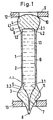
- the glass piston B shown greatly enlarged in the drawing, is suitable for use in a sprinkler S, the abutments of which are designated 12 and 13.
- the glass bulb B has a thin, thermally highly active shaft 1 with a sealed chamber 1.1, in which the explosive liquid 2 is located. A small bubble 2.1 is shown in the explosive liquid.
- the two ends which are generally designated 3 and 4, are thickened like a bead compared to the thin shaft 1 and they absorb unfavorable shear and tensile stresses.
- the end 3 shown in the drawing below carries a filler neck 7 which is closed at 8.
- Transition sections 5 and 6 between the shaft 1 and the ends 3 and 4 are evenly grooved by outer transition lines 3.1 and 4.1, which ensures a favorable introduction of force into the thin shaft 1 without unfavorable stress peaks, so that pure compressive stresses occur in this area.
- the chamber 1.1 has a cylindrical section 1.2 with rounded corners in the area of the upper end 4 and an inner transition line 1.3 in the area of the lower end 3.
- the corresponding geometric design of the transition sections 5 and 6 between the thin shaft 1 and the ends 3 and 4 results in reinforcement sections 3.2 and 4.2, the shape and smooth contour of which can be clearly seen in the drawing.
- the thin and slim glass bulb in the area of the bearing surfaces 10, 11 has a relatively large diameter in relation to the shaft 1, larger areas are available in this area for the force absorption, so that the surface pressures do not become too great.
- the spherical sections of the supports 10, 11 together with the abutments 12, 13 form joints which avoid bending stresses on the shaft.
- the distance between the contact surfaces 10, 11 was approximately 20 mm.
- the length of the thin, thermally active shaft 1 was approximately 15 mm, its outer diameter was approximately 3 mm and the wall thickness was approximately 0.4 mm.
- the outer diameter of the bead-like ends 3, 4 was approximately 4 mm.
- the triggering times of the glass bulb described were more than five times shorter compared to conventional glass bulb with a diameter of 8 to 10 mm, with approximately the same strength.
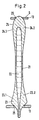
- Fig. 2 The embodiment shown in Fig. 2 is very similar to that of Fig. 1.
- the transition sections between the ends 23 and 24 and the shaft 21 are much more elongated and the transition lines 23.1 and 24.1 and the reinforcements 23.2 and 24.2 run correspondingly differently.
- the chamber 22 is also shaped accordingly, as becomes clear when viewing FIG. 2.
- the regions of the ends 23 and 24 which abut the abutments 12 and 13 of the sprinkler S or are in engagement therewith are denoted by 25 and 26, respectively.
- the gradual increase in the diameter and the wall thickness in the region of the ends of the glass bulb ensures a correspondingly favorable introduction of force and distribution.
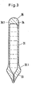
- FIG. 3 differs essentially from that according to FIG. 1 in that only the end 33, which has the filler neck 7, has an enlarged diameter.
- the formation of the end 33 with the transition line 33.1 corresponds to the end 3 with the transition line 3.1 of the embodiment according to FIG. 1.
- the upper end 34 does not have an enlarged diameter.
- the transition from the shaft 31 takes place through the transition line 34.1 shown without a larger diameter to form the seating area 35.
Description
Die Erfindung betrifft einen Glaskolben nach dem Oberbegriff des Patentanspruches 1.The invention relates to a glass bulb according to the preamble of claim 1.
In Sprinklem, dem Hauptanwendungsgebiet für Glaskolben, halten diese als thermisch aktives Auslöseglied ein Ventil geschlossen. Sie sind in der Regel axial zwischen zwei Widerlagern des Sprinklers eingespannt, von denen das eine die Kräfte des Ventils überträgt. Im Brandfalle zerspringt der Glaskolben und gibt die Ventilöffnung und damit das Löschmedium, vorzugsweise Wasser, frei.In Sprinklem, the main area of application for glass pistons, these keep a valve closed as a thermally active trigger element. They are usually clamped axially between two abutments of the sprinkler, one of which transmits the forces of the valve. In the event of a fire, the glass bulb bursts and releases the valve opening and thus the extinguishing medium, preferably water.
Ein solcher Glaskolben besteht normalerweise aus einem walzen- oder tonnenförmigen Schaft unterschiedlichster Länge, häufig mit Kröpfungen in der Wand oder Eweiterungen zur Mitte hin, der zusammen mit der sich ausdehnenden Flüssigkeit, kurz Sprengflüssigkeit genannt, den eigentlichen thermischen aktiven Teil bildet. Der Schaft wird an beiden Enden durch flache, kegelige oder gewölbte, im wesentlichen thermisch inaktive Enden begrenzt, die die Auflager für die Widerlager des Sprinklers bilden. Eines der Enden hat gewöhnlich einen Füllstutzen, durch den die Sprengflüssigkeit eingefüllt wird und der danach verschlossen wird.Such a glass bulb usually consists of a barrel or barrel-shaped shaft of various lengths, often with cranking in the wall or extensions towards the center, which together with the expanding liquid, or explosive liquid for short, forms the actual thermally active part. The shaft is delimited at both ends by flat, conical or curved, essentially thermally inactive ends, which form the supports for the abutment of the sprinkler. One of the ends usually has a filler neck through which the explosive liquid is filled and which is then closed.
Der Glaskolben muß eine bestimmte, von der Art der Ventilkonstruktion oder der Auslöseeinrichtung abhängige Dauerlast aufnehmen können, damit der Sprinkler über viele Jahrzehnte sicher geschlossen bleibt und dabei ständig in Bereitschaft gehalten wird.The glass bulb must be able to absorb a certain permanent load, depending on the type of valve construction or the triggering device, so that the sprinkler remains securely closed for many decades and is always kept ready.
Bekannte Glaskolben, die die entsprechenden Zulassungsanforderungen erfüllen, haben einen Durchmesser zwischen 8 und 12 mm bei Wandstärken von 1 bis 1, 5 mm und eine Baulänge von insgesamt 20 bis 30 mm. Derartige relativ dicke Glaskolben führen wegen ihrer ungünstigen Verhältnisse von wärmeaufnehmender Oberfläche zu aufheizendem Volumen zu langen Auslösezeiten. Ein Kugelförmiger Glaskolben hat diesbezüglich die denkbar ungünstigste Form.Known glass bulbs that meet the corresponding approval requirements have a diameter between 8 and 12 mm with wall thicknesses of 1 to 1.5 mm and a total length of 20 to 30 mm. Such relatively thick glass bulbs lead to long triggering times because of their unfavorable conditions from the heat-absorbing surface to the heating volume. In this regard, a spherical glass bulb has the worst possible shape.
Die Anforderungen an die Glaskolben für Sprinkler für automatische Feuerlöschanlagen und analog für andere thermische Auslöseeinrichtungen gehen dahin, daß zunehmend sehr viel kürzere Auslösezeiten und zwar bis fast zu einer Zehnerpotenz niedriger gefordert werden. Soll gleichzeitig die Forderung, die Sprinkler selbst in ihrer bewährten Konstruktion nicht wesentlich zu ändern, erfüllt werden, darf die Dauerfestigkeit der Glaskolben bei axialer Belastung grundsätzlich nicht abnehmen.The requirements for the glass pistons for sprinklers for automatic fire extinguishing systems and, analogously, for other thermal triggering devices are that increasingly shorter triggering times are required, down to a power of ten. If at the same time the requirement not to significantly change the sprinklers even in their tried-and-tested design is to be met, the fatigue strength of the glass pistons must not decrease under axial load.
Ein Vorschlag, diesen Forderungen gerecht zu werden, besteht darin, das Volumen der Sprengflüssigkeit in dem Glaskolben durch Verdrängungskörper zu verkleinern, ohne daß der Glaskörper in seinen Abmessungen und damit hinsichtlich seiner Festigkeitseigenschaften verändert wird (DE-A 3 220124).One proposal to meet these requirements is to reduce the volume of the explosive liquid in the glass bulb by means of displacement bodies without the glass body being changed in its dimensions and thus in terms of its strength properties (DE-A 3 220124).
Es ist auch schon versucht worden, die Auslösezeiten dadurch zu verringern, daß man den Durchmesser des Glaskolbens insgesamt verkleinert hat, so daß das Verhältnis von Oberfläche zum Volumen der Sprengflüssigkeit günstiger wurde.Attempts have also been made to reduce the triggering times by reducing the diameter of the glass bulb overall, so that the ratio of surface area to volume of the explosive fluid has become more favorable.
Diese Versuche führten aber zu einer nicht akzeptablen Verringerung der Festigkeit.However, these attempts resulted in an unacceptable reduction in strength.
Der Erfindung liegt nun die Aufgabe zugrunde, einen Glaskolben der eingangs genannten Art zu schaffen, der ohne wesentliche Einbuße an seine Festigkeit und an seine Dauerbelastbarkeit den neuen Anforderungen entsprechend schnell anspricht, d.h. im Brandfalle zerstört wird und wirtschaftlich hergestellt werden kann.The invention is based on the object of providing a glass bulb of the type mentioned at the outset which responds quickly to the new requirements without any significant loss of strength and durability. is destroyed in the event of fire and can be produced economically.
Diese Aufgabe wird grundsätzlich durch das Kennzeichen des Anspruches 1 gelöst, wobei in vorteilhafter Weise beide Enden einen äußeren Durchmesser aufweisen, wie in Anspruch 2 angegeben.This object is basically achieved by the characterizing part of claim 1, both ends advantageously having an outer diameter, as stated in
Um die gestellten technischen Anforderungen zu erfüllen sind Anwendungsfälle mit nur einem einen größeren Durchmesser aufweisenden Ende denkbar, das dann den Füllstutzen trägt, in dem häufig die, dieses Ende zusätzlich schwächende Füllkapillare liegt.In order to meet the technical requirements, applications are conceivable with only one end having a larger diameter, which then carries the filler neck, in which the filling capillary, which additionally weakens this end, is often located.
Durch die Wahl eines besonders dünnen Schaftes, dem eigentlich thermisch aktiven Teil des Glaskolbens, wird ein günstiges Verhältnis zwischen der Oberfläche und dem Volumen des Schaftes und damit auch der Sprengflüssigkeit erreicht. Relativ zur Durchmesserverringerung wird dadurch sogar eine überproportionale Verkürzung der Auslösezeit erzielt.By choosing a particularly thin shaft, the actually thermally active part of the glass bulb, a favorable ratio between the surface and the volume of the shaft and thus also the explosive liquid is achieved. Relative to the reduction in diameter, this results in a disproportionate reduction in the tripping time.
Die mit einer Verminderung des Durchmessers des Schaftes einhergehende an sich unvermeidbare Herabsetzung der Festigkeit des Glaskolbens wird durch seine erfindungsgemäß besondere Gestaltung unter konsequenter Ausnutzung der Materialeigenschaften des Werkstoffes Glas aufgefangen.The inherently unavoidable reduction in the strength of the glass bulb associated with a reduction in the diameter of the shaft is compensated for by its special design according to the invention with consistent use of the material properties of the material glass.
Vorzugsweise beide Enden des Glaskolbens sind gegenüber dem Schaft solcherart in ihren Durchmessern vergrößert, daß dort alle für Glas ungünstigen Scher- und Zugspannungen und auch die an den dadurch ebenfalls ermöglichten relativ großen Auflageflächen auftretenden Flächenpressungen unterhalb kritischer Werte bleiben.Both ends of the glass bulb are preferably enlarged in diameter compared to the shaft in such a way that all shear and tensile stresses which are unfavorable for glass and also the surface pressures occurring on the relatively large contact surfaces which are also made possible thereby remain below critical values.
Die von den Auflagern aufgenommenen Kräfte werden in dem oder den sockelartig verdickten Enden übertragen, verteilt und frei von allen Biege-und Scherspannungen möglichst gleichmäßig axial in den als verjüngte Säule ausgebildeten Schaft eingeleitet. Da die Festigkeit von Glas gegenüber Druckbeanspruchung etwa zwanzigmal größer ist als bei Zugbeanspruchung, und durch die beschriebene erfindungsgemäße Gestaltung des Glaskolbens im Bereich des Schaftes reine Druckspannungen auftreten, wird die besonders dünne und schlanke spezifisch hochbelastbare Form des Schaftes erst ermöglicht.The forces absorbed by the supports are transmitted in the base or ends thickened like a base, distributed and introduced axially as free as possible from all bending and shear stresses into the shaft designed as a tapered column. Since the strength of glass against compressive stress is about twenty times greater than that of tensile stress, and due to the described design of the glass bulb according to the invention pure compressive stresses occur in the stem, the particularly thin and slim, specifically heavy-duty shape of the stem is only made possible.
Bei der bei Versuchen schrittweise durchgeführten Verringerung des Durchmessers des Glaskolbens wurden in dem den Füllstutzen tragenden Ende des Glaskolbens zuerst kritische Festigkeitswerte überschritten. Wenn nur eine mäßige Verkürzung der Auslösezeit angestrebt wird oder gewisse Einbußen der Festigkeit hingenommen werden, genügt bis zu bestimmten Grenzen, wenn nur das den Füllstutzen tragende Ende des Glaskolbens einen größeren Durchmesser als der Schaft aufweist. Dies bringt schon große Vorteile.When the diameter of the glass bulb was gradually reduced in tests, critical strength values were first exceeded in the end of the glass bulb carrying the filler neck. If only a moderate reduction in the triggering time is desired or a certain loss in strength is accepted, it is sufficient to a certain extent if only the end of the glass bulb carrying the filler neck has a larger diameter than the shaft. This already has great advantages.
Dadurch, daß, wie in Anspruch 4 angegeben, sogenannte Übergangsabschnitte zwischen der oder den Verdickungen und dem Schaft vorgesehen sind, erfolgt die Ein- und Oberleitung der Kräfte in diesem kritischen Bereich besonders günstig unter Vermeidung von Spannungsspitzen. Die Übergangsabschnitte können unterschiedlich geformt sein und sollen für einen allmählichen und weichen Übergang der Kräfte in den dünnen Schaft sorgen.In that, as stated in claim 4, so-called transition sections between the or the thickenings and the shaft are provided, the introduction and catenary of the forces in this critical area are carried out particularly advantageously, avoiding voltage peaks. The transition sections can be shaped differently and are intended to ensure a gradual and smooth transfer of the forces into the thin shaft.
In vorteilhafter Weise kann die Verdickung an einem Ende oder können die Verdickungen an beiden Enden wie in Anspruch 5 angegeben, im Bereich der Auflageflächen annähernd kugelförmig sein, um zusammen mit dem Widerlager ein Gelenk zu bilden, so daß auch bei gelegentlich unvermeidlicher seitlicher Verschiebung der beiden Widerlager Biegebeanspruchungen in dem dünnen Schaft vermieden werden.Advantageously, the thickening at one end or the thickening at both ends can be approximately spherical in the area of the bearing surfaces in order to form a joint together with the abutment, so that even with occasional unavoidable lateral displacement of the two Abutment bending stresses in the thin shaft can be avoided.
In Anspruch 6 ist eine Ausführungsform unter Schutz gestellt, die sich bei praktischen Versuchen bewährt hat.In
Im folgenden wird die Erfindung unter Hinweis auf die Zeichnung anhand dreier Ausführungsformen näher erläutert.The invention is explained in more detail below with reference to the drawing using three embodiments.
Es zeigt:
- Fig. 1 einen schematischen Schnitt, stark vergrößert, durch eine Ausführungsform eines Glaskolbens nach der Erfindung;
- Fig. 2 einen der Fig. 1 entsprechenden Schnitt durch eine andere Ausführungsform; und
- Fig. 3 eine den Fig. 1 und 2 entsprechenden Schnitt durch noch eine andere Ausführungsform eines Glaskolbens nach der Erfindung.
- 1 shows a schematic section, greatly enlarged, through an embodiment of a glass bulb according to the invention.
- FIG. 2 shows a section corresponding to FIG. 1 through another embodiment; and
- 3 shows a section corresponding to FIGS. 1 and 2 through yet another embodiment of a glass bulb according to the invention.
Der in der Zeichnung stark vergrößert dargestellte Glaskolben B ist zum Einsatz in einen Sprinkler S geeignet, dessen Widerlager mit 12 und 13 bezeichnet sind. Der Glaskolben B weist einen dünnen, thermisch hochaktiven Schaft 1 mit einer dichten Kammer 1.1 auf, in der sich die Sprengflüssigkeit 2 befindet. In der Sprengflüssigkeit ist ein kleines Bläschen 2.1 dargestellt.The glass piston B, shown greatly enlarged in the drawing, is suitable for use in a sprinkler S, the abutments of which are designated 12 and 13. The glass bulb B has a thin, thermally highly active shaft 1 with a sealed chamber 1.1, in which the
Die beiden Enden, die grundsätzlich mit 3 und 4 bezeichnet sind, sind gegenüber dem dünnen Schaft 1 wulstartig verdickt und sie fangen ungünstige Scher- und Zugspannungen auf. Das in der Zeichnung unten dargestellte Ende 3 trägt einen Füllstutzen 7, der bei 8 verschlossen ist.The two ends, which are generally designated 3 and 4, are thickened like a bead compared to the thin shaft 1 and they absorb unfavorable shear and tensile stresses. The
Übergangsabschnitte 5 und 6 zwischen dem Schaft 1 und den Enden 3 und 4 sind durch äußere Übergangslinien 3.1 und 4.1 gleichmäßig gekehlt, wodurch für eine günstige Krafteinleitung in den dünnen Schaft 1 ohne ungünstige Spannungsspitzen gesorgt wird, so daß in diesem Bereich reine Druckspannungen auftreten.
Die Kammer 1.1 weist im Bereich des oberen Endes 4 einen zylindrischen Abschnitt 1.2 mit abgerundeten Ecken und im Bereich des unteren Endes 3 eine innere Übergangslinie 1.3 auf. Durch die entsprechende geometrische Gestaltung der Übergangsabschnitte 5 und 6 zwischen dem dünnen Schaft 1 und den Enden 3 und 4 entstehen Verstärkungsabschnitte 3.2 und 4.2, deren Gestalt und glatter Konturenverlauf der Zeichnung deutlich zu entnehmen ist.The chamber 1.1 has a cylindrical section 1.2 with rounded corners in the area of the upper end 4 and an inner transition line 1.3 in the area of the
Dadurch, daß der dünne und schlanke Glaskolben im Bereich der Auflageflächen 10, 11 einen im Verhältnis zum Schaft 1 relativ großen Durchmesser aufweist, stehen in diesem Bereich größere Flächen zur Kraftaufnahme zur Verfügung, so daß die Flächenpressungen nicht zu groß werden. Außerdem bilden die kugelförmigen Abschnitte der Auflager 10, 11 zusammen mit den Widerlagern 12, 13 Gelenke, die Biegebeanspruchungen des Schaftes vermeiden.Because the thin and slim glass bulb in the area of the
Bei einem ausgeführten Beispiel mit einer Gesamtlänge des Glaskolbens von ca. 25 mm betrug der Abstand zwischen den Auflageflächen 10, 11 ca. 20 mm. Die Länge des dünnen, thermisch aktiven Schaftes 1 betrug ca. 15 mm, sein Außendurchmesser knapp 3 mm und die Wandstärke etwa 0, 4 mm. Der Außendurchmesser der wulstartig verdickten Enden 3, 4 lag bei ca. 4 mm.In an example carried out with a total length of the glass bulb of approximately 25 mm, the distance between the
Ein Glaskolben in üblicher Weise geformt, ohne die erfindungsgemäß beschriebene Gestaltung mit verdickten Enden, erreichte bei gleichem Durchmesser von ca. 3 mm bei axialer Belastung ein Viertel der Festigkeit bezogen auf den Querschnitt im Schaft.A glass bulb shaped in the usual way, without the design with thickened ends described according to the invention, achieved a quarter of the strength in relation to the cross section in the shaft with the same diameter of about 3 mm under axial load.
Die Auslösezeiten des beschriebenen Glaskolbens waren mehr als fünfmal kürzer im Vergleich zu herkömmlichen Glaskolben mit einem Durchmesser von 8 bis 10 mm, bei etwa gleicher Festigkeit.The triggering times of the glass bulb described were more than five times shorter compared to conventional glass bulb with a diameter of 8 to 10 mm, with approximately the same strength.
Es wurden bereits erfolgreiche Versuche mit noch dünneren, schnelleren und dennoch festen Glaskolben der erfindungsgemäß beschriebenen Art mit weniger als 2 mm Durchmesser des Schaftes durchgeführt.Successful tests have already been carried out with even thinner, faster, yet firm glass bulbs of the type described according to the invention with less than 2 mm diameter of the shaft.
Die in Fig. 2 dargestellte Ausführungsform ist derjenigen nach Fig. 1 sehr ähnlich. Die Übergangsabschnitte zwischen den Enden 23 und 24 und dem Schaft 21 sind sehr viel langgestreckter und entsprechend anders verlaufen die Übergangslinien 23.1 und 24.1 bzw. die Verstärkungen 23.2 und 24.2. Auch die Kammer 22 ist entsprechend geformt, wie beim Betrachten der Fig. 2 deutlich wird. Die Bereiche der Enden 23 und 24, die an den Widerlagern 12 und 13 des Sprinklers S anliegen bzw. mit diesen im Eingriff stehen, sind mit 25 bzw. 26 bezeichnet.The embodiment shown in Fig. 2 is very similar to that of Fig. 1. The transition sections between the
Ebenso wie bei der Ausführungsform nach Fig. 1 sorgt die allmähliche Zunahme des Durchmessers und der Wandstärke im Bereich der Enden des Glaskolbens für eine entsprechend günstige Krafteinleitung und Verteilung.As in the embodiment according to FIG. 1, the gradual increase in the diameter and the wall thickness in the region of the ends of the glass bulb ensures a correspondingly favorable introduction of force and distribution.
Die in Fig. 3 dargestellte Ausführungsform unterscheidet sich dadurch im wesentlichen von derjenigen nach Fig. 1, daß lediglich das Ende 33, das den Füllstutzen 7 aufweist, einen erweiterten Durchmesser hat. Die Ausbildung des Endes 33 mit der Übergangslinie 33.1 entspricht dem Ende 3 mit der Übergangslinie 3.1 der Ausführungsform nach Fig. 1.The embodiment shown in FIG. 3 differs essentially from that according to FIG. 1 in that only the
Das oben liegende Ende 34 hat keinen erweiterten Durchmesser. Der Übergang von dem Schaft 31 erfolgt durch die dargestellte Übergangslinie 34.1 ohne größeren Durchmesser zur Ausbildung des Sitzbereiches 35.The
Claims (6)
Priority Applications (1)
| Application Number | Priority Date | Filing Date | Title |
|---|---|---|---|
| AT86111609T ATE47321T1 (en) | 1985-09-09 | 1986-08-22 | PISTON FOR SPRINKLER FOR FIRE EXTINGUISHING SYSTEMS OR OTHER THERMAL TRIGGERING DEVICES. |
Applications Claiming Priority (4)
| Application Number | Priority Date | Filing Date | Title |
|---|---|---|---|
| DE3532042 | 1985-09-09 | ||
| DE3532042 | 1985-09-09 | ||
| DE19863601203 DE3601203A1 (en) | 1985-09-09 | 1986-01-17 | GLASS BOTTLES FOR SPRINKLERS FOR FIRE EXTINGUISHING SYSTEMS OR OTHER THERMAL RELEASE DEVICES |
| DE3601203 | 1986-01-17 |
Publications (2)
| Publication Number | Publication Date |
|---|---|
| EP0215331A1 EP0215331A1 (en) | 1987-03-25 |
| EP0215331B1 true EP0215331B1 (en) | 1989-10-18 |
Family
ID=25835778
Family Applications (1)
| Application Number | Title | Priority Date | Filing Date |
|---|---|---|---|
| EP86111609A Expired EP0215331B1 (en) | 1985-09-09 | 1986-08-22 | Glass bulb for a fire sprinkler or other thermally activated system |
Country Status (3)
| Country | Link |
|---|---|
| EP (1) | EP0215331B1 (en) |
| AU (1) | AU583649B2 (en) |
| DE (2) | DE3601203A1 (en) |
Cited By (1)
| Publication number | Priority date | Publication date | Assignee | Title |
|---|---|---|---|---|
| DE202010013607U1 (en) | 2010-09-27 | 2011-12-28 | Job Lizenz Gmbh & Co. Kg | Thermal release element for a thermally controlled switching element |
Families Citing this family (16)
| Publication number | Priority date | Publication date | Assignee | Title |
|---|---|---|---|---|
| US4739835A (en) * | 1986-06-23 | 1988-04-26 | Central Sprinkler Corp. | Quick response glass bulb sprinkler |
| NZ220118A (en) * | 1987-04-28 | 1990-10-26 | David John Picton | Pipeline fluid over temperature protection fitting |
| DE3808384C2 (en) * | 1987-07-06 | 1990-03-22 | Total Feuerschutz Gmbh | Trigger link for thermal and / or electrical triggering of a fire protection system |
| US4898246A (en) * | 1987-07-06 | 1990-02-06 | Total Walther Feuerschutz Gmbh | Quick release valve for sprinkler head |
| DE3822696A1 (en) * | 1988-03-12 | 1990-01-11 | Total Feuerschutz Gmbh | Release member |
| DE3819749A1 (en) * | 1988-06-10 | 1989-12-14 | Verband Der Sachversicherer Ev | THERMAL RELEASE DEVICE FOR SPRINKLERS FOR FIXED FIRE EXTINGUISHING SYSTEMS |
| DE3844696C2 (en) * | 1988-07-05 | 1992-01-23 | Total Walther Feuerschutz Gmbh, 5000 Koeln, De | Triggering element for sprinkler installations |
| DE3940453C1 (en) * | 1989-12-07 | 1991-01-31 | Total Walther Feuerschutz Gmbh, 5000 Koeln, De | |
| GB2239394B (en) * | 1989-12-27 | 1994-04-20 | Total Feuerschutz Gmbh | A triggering element for a fire protection element |
| US5829532A (en) | 1997-03-07 | 1998-11-03 | Central Sprinkler Corporation | Low pressure, early suppression fast response sprinklers |
| DE10219079B4 (en) * | 2002-04-29 | 2004-06-03 | Minimax Gmbh | Process for making glass ampoules |
| DE202009007987U1 (en) | 2009-06-05 | 2010-10-28 | Job Lizenz Gmbh & Co. Kg | Thermal release element for sprinklers, valves or the like. |
| DE202011050661U1 (en) | 2011-07-07 | 2011-09-09 | Job Lizenz Gmbh & Co. Kg | Thermal release element for sprinklers, valves or the like |
| DE202013102312U1 (en) | 2013-05-28 | 2014-08-29 | Job Lizenz Gmbh & Co. Kg | Thermal release element |
| DE202015103950U1 (en) | 2015-07-28 | 2016-11-02 | Job Lizenz Gmbh & Co. Kg | Thermal release element |
| DE202017103682U1 (en) | 2017-06-21 | 2018-09-24 | Job Lizenz Gmbh & Co. Kg | Thermal release element |
Family Cites Families (2)
| Publication number | Priority date | Publication date | Assignee | Title |
|---|---|---|---|---|
| GB409569A (en) * | 1933-09-12 | 1934-05-03 | Willis Kennedy Hodgman Jr | Improvements in or relating to frangible struts adapted to be burst on expansion of a fluid contained therein, such as are used in fireextinguishing apparatus |
| DE3220124A1 (en) * | 1982-05-28 | 1983-12-01 | Walther & Cie AG, 5000 Köln | RELEASE MEMBER FOR A SPRINKLER |
-
1986
- 1986-01-17 DE DE19863601203 patent/DE3601203A1/en not_active Withdrawn
- 1986-08-20 AU AU61633/86A patent/AU583649B2/en not_active Expired
- 1986-08-22 DE DE8686111609T patent/DE3666353D1/en not_active Expired
- 1986-08-22 EP EP86111609A patent/EP0215331B1/en not_active Expired
Cited By (2)
| Publication number | Priority date | Publication date | Assignee | Title |
|---|---|---|---|---|
| DE202010013607U1 (en) | 2010-09-27 | 2011-12-28 | Job Lizenz Gmbh & Co. Kg | Thermal release element for a thermally controlled switching element |
| EP2433677A2 (en) | 2010-09-27 | 2012-03-28 | Job Lizenz GmbH & Co. KG | Thermal release element for a thermally controlled switch element |
Also Published As
| Publication number | Publication date |
|---|---|
| AU583649B2 (en) | 1989-05-04 |
| DE3601203A1 (en) | 1987-03-19 |
| DE3666353D1 (en) | 1989-11-23 |
| EP0215331A1 (en) | 1987-03-25 |
| AU6163386A (en) | 1987-03-12 |
Similar Documents
| Publication | Publication Date | Title |
|---|---|---|
| EP0215331B1 (en) | Glass bulb for a fire sprinkler or other thermally activated system | |
| CH652966A5 (en) | METHOD FOR PRODUCING A PACKAGING CONTAINER AND TUBE-CONTAINER CONTAINED THEREFORE. | |
| DE2832607A1 (en) | ELASTIC DOUBLE RING SEAL | |
| DE1916578A1 (en) | Steering linkages for motor vehicles | |
| EP1042147B1 (en) | Nozzle element for an automobile windshield washer system | |
| DE2211129A1 (en) | Process for the production of pipes from compound material | |
| DE3312702C2 (en) | ||
| DE3141416C2 (en) | Device for fastening a cover on a housing, in particular a valve housing | |
| DE3806162A1 (en) | FLANGE CONNECTION | |
| CH669827A5 (en) | ||
| DE2221511A1 (en) | Gate valve | |
| DE3802580A1 (en) | POT WAREHOUSES FOR CONSTRUCTIONS LIKE BRIDGES AND THE LIKE | |
| DE738364C (en) | Elastic bearing to absorb tensile, compressive and thrust forces | |
| DE1292952C2 (en) | BALL JOINT | |
| DE4319054A1 (en) | Plastic retaining means, in particular for roof fastenings | |
| DE2834403A1 (en) | PRINT STORAGE | |
| DE2415774A1 (en) | MATRIX FOR THE PRODUCTION OF BARS OR WIRE FROM COMPOSITE MATERIAL WITH A NON-ROUND CROSS SECTION | |
| DE3825916A1 (en) | RING SEAL | |
| DE19948848C1 (en) | Nozzle brick for injecting flushing gas into molten metal in a metallurgical vessel has a gas entry opening located at least partially outside the pitch circle of a biasing spring of a non-return valve within a gas supply pipe | |
| DE886983C (en) | Elastic joint and support device | |
| CH526066A (en) | Pressure line connection with pressure line nipple, counterpart and union nut | |
| CH636933A5 (en) | Device for attaching an element to a pipe | |
| DE2006109B2 (en) | Metal tube frames for bed frames, table frames or the like, in particular for frames for motor vehicle seats | |
| DE954322C (en) | Set of flanged gutter profiles, preferably for the expansion of the sliding bend | |
| DE1960922U (en) | BALL JOINT. |
Legal Events
| Date | Code | Title | Description |
|---|---|---|---|
| PUAI | Public reference made under article 153(3) epc to a published international application that has entered the european phase |
Free format text: ORIGINAL CODE: 0009012 |
|
| AK | Designated contracting states |
Kind code of ref document: A1 Designated state(s): AT BE CH DE FR GB IT LI LU NL SE |
|
| 17P | Request for examination filed |
Effective date: 19870423 |
|
| 17Q | First examination report despatched |
Effective date: 19880810 |
|
| GRAA | (expected) grant |
Free format text: ORIGINAL CODE: 0009210 |
|
| AK | Designated contracting states |
Kind code of ref document: B1 Designated state(s): AT BE CH DE FR GB IT LI LU NL SE |
|
| PG25 | Lapsed in a contracting state [announced via postgrant information from national office to epo] |
Ref country code: BE Effective date: 19891018 Ref country code: NL Effective date: 19891018 Ref country code: SE Effective date: 19891018 |
|
| REF | Corresponds to: |
Ref document number: 47321 Country of ref document: AT Date of ref document: 19891115 Kind code of ref document: T |
|
| ITF | It: translation for a ep patent filed |
Owner name: BARZANO' E ZANARDO MILANO S.P.A. |
|
| REF | Corresponds to: |
Ref document number: 3666353 Country of ref document: DE Date of ref document: 19891123 |
|
| GBT | Gb: translation of ep patent filed (gb section 77(6)(a)/1977) | ||
| ET | Fr: translation filed | ||
| NLV1 | Nl: lapsed or annulled due to failure to fulfill the requirements of art. 29p and 29m of the patents act | ||
| PLBE | No opposition filed within time limit |
Free format text: ORIGINAL CODE: 0009261 |
|
| STAA | Information on the status of an ep patent application or granted ep patent |
Free format text: STATUS: NO OPPOSITION FILED WITHIN TIME LIMIT |
|
| PG25 | Lapsed in a contracting state [announced via postgrant information from national office to epo] |
Ref country code: AT Effective date: 19900822 |
|
| PG25 | Lapsed in a contracting state [announced via postgrant information from national office to epo] |
Ref country code: LU Free format text: LAPSE BECAUSE OF NON-PAYMENT OF DUE FEES Effective date: 19900831 |
|
| 26N | No opposition filed | ||
| ITTA | It: last paid annual fee | ||
| REG | Reference to a national code |
Ref country code: GB Ref legal event code: IF02 |
|
| PGFP | Annual fee paid to national office [announced via postgrant information from national office to epo] |
Ref country code: DE Payment date: 20050705 Year of fee payment: 20 |
|
| PGFP | Annual fee paid to national office [announced via postgrant information from national office to epo] |
Ref country code: GB Payment date: 20050808 Year of fee payment: 20 |
|
| PGFP | Annual fee paid to national office [announced via postgrant information from national office to epo] |
Ref country code: FR Payment date: 20050819 Year of fee payment: 20 |
|
| PGFP | Annual fee paid to national office [announced via postgrant information from national office to epo] |
Ref country code: CH Payment date: 20050824 Year of fee payment: 20 |
|
| PGFP | Annual fee paid to national office [announced via postgrant information from national office to epo] |
Ref country code: IT Payment date: 20050826 Year of fee payment: 20 |
|
| PG25 | Lapsed in a contracting state [announced via postgrant information from national office to epo] |
Ref country code: GB Free format text: LAPSE BECAUSE OF EXPIRATION OF PROTECTION Effective date: 20060821 |
|
| REG | Reference to a national code |
Ref country code: GB Ref legal event code: PE20 |
|
| REG | Reference to a national code |
Ref country code: CH Ref legal event code: PL |