EP0214822A2 - Montage de dispositifs soniques - Google Patents
Montage de dispositifs soniques Download PDFInfo
- Publication number
- EP0214822A2 EP0214822A2 EP86306703A EP86306703A EP0214822A2 EP 0214822 A2 EP0214822 A2 EP 0214822A2 EP 86306703 A EP86306703 A EP 86306703A EP 86306703 A EP86306703 A EP 86306703A EP 0214822 A2 EP0214822 A2 EP 0214822A2
- Authority
- EP
- European Patent Office
- Prior art keywords
- devices
- sonic
- plastics material
- array
- block
- Prior art date
- Legal status (The legal status is an assumption and is not a legal conclusion. Google has not performed a legal analysis and makes no representation as to the accuracy of the status listed.)
- Withdrawn
Links
Images
Classifications
-
- G—PHYSICS
- G10—MUSICAL INSTRUMENTS; ACOUSTICS
- G10K—SOUND-PRODUCING DEVICES; METHODS OR DEVICES FOR PROTECTING AGAINST, OR FOR DAMPING, NOISE OR OTHER ACOUSTIC WAVES IN GENERAL; ACOUSTICS NOT OTHERWISE PROVIDED FOR
- G10K11/00—Methods or devices for transmitting, conducting or directing sound in general; Methods or devices for protecting against, or for damping, noise or other acoustic waves in general
- G10K11/004—Mounting transducers, e.g. provided with mechanical moving or orienting device
Definitions
- This invention relates to the mounting of sonic devices by which term is meant a transducer for the transmission and/or reception of sound energy.
- An object of the present invention therefore is to provide ways of mounting and locating one sonic device, or a number of sonic devices, e.g. to form an array, without having a complex supporting construction, but at the same time providing for optimum performance of each device once mounted and located.
- At least one sonic device is mounted and located in a block of acoustically-opaque foamed plastics materials, with the sensitive head or heads left uncovered by the plastics material.
- the foamed plastics material used for the formation of the block may vary according to requirements, but it may specifically be BIBBITHANE ISOFOAM 510 prepared and cured in accordance with the manufacturers' instructions.
- the foamed plastics material may have closed cells which are filled with gas generated during foaming. This feature is found to improve the mechanical decoupling of one sonic device from each other device of the array, by virtue of the gas within the foam itself, which makes the material acoustically opaque.
- the, or each, sonic device is located within a mould, preferably by its sensitive- head, and a body of foamed plastics material is moulded around it.
- each sonic device Whilst it is envisaged that in most cases an array of sonic devices will be located within a single block of foamed plastics material, in certain circumstances, it may be appropriate for each sonic device to be located in an individual foamed plastics block, and for such blocks then to be assembled into an array.
- the block with its sonic device or devices is preferably mounted in a sealed casing to protect it against sea water, for example.
- a space between a wall of the casing and the heads of the devices may be filled with an acoustic coupling material.
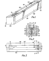
- Figure 1 illustrates a typical moulding tool 10 employed with the present invention and having a base 10A, end walls 10B and 10C, and side walls 10D and 10 E , the latter having a recess 10F between them and defining a ledge 10G (see Figure 2) which forms the top of the mould.
- a single longitudinal cavity 10H is formed within which an array of sonic devices 11 can be located, the array comprising two longitudinal rows of spaced devices.
- the location of the sonic devices within the mould is accurately carried out firstly by locating the sensitive heads 24 of the devices in locating recesses 10J of the base 10A. Thereafter, and before the remainder of the mould 10B, C, D, E, G is assembled, appropriate wiring of the devices takes place.
- Each sonic device is coated with an appropriate releasing agent in order that the foamed plastics material to be moulded will not stick to it, since this would affect the vibration of the device.
- Each pair of pins 12 is connected to one of a series of horizontal bars 14 (one is shown in Figure 3), each of which, in turn, is connected to a pair of further supports 16 projecting upwardly therefrom.
- the sonic devices are accurately located and secured wtihin the mould cavity 10H prior to a moulding operation, during which foamed plastics ' material is either poured, or injected, into the cavity via one or more injecting sprues or holes 18 formed in the ledge 10G as shown in Figure 3.
- the choice of foam e.g. BIBBITHANE ISOFOAM 510, is such that the injection, and curing can take place at room temperature. During curing, the holes 18 may be sealed. If the foamed plastics material requires heat- curing this can- be carried out in an oven.
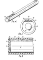
- the resulting foam block 22 is shown diagrammatically in Figure 4. It provides a lightweight structure in which all of the array of sonic devices are effectively encapsulated, although, as shown in Figure 4, the element heads 24 of the array of devices are left proud of the block and uncovered by the foam.
- the foam moulding operation is such that the foam is formed with closed cells containing gas generated during moulding.
- the resulting closed gas-filled cavity foam is rigid enough to provide an effective mounting for the devices, and to give protection against shocks.
- the gas-filled foam has acoustic opacity to prevent acoustic coupling between devices.
- the end walls 10B and 10C are preferably provided with circular recesses (not shown) so that the end product has integral disc-like protuberances 20.
- the resultant block of foamed plastics material with the array of sonic devices embedded therein is now mounted in the manner shown in Figures 5 and 6 in a casing 30 of acrylic material.
- the casing comprises a longitudinal tube having end caps 32 of the form shown in Figure 6.
- This space 34 is filled with an acoustic coupling medium 35, which may, for example, be a semi-liquid, petroleum jelly, lanolin, silicon oil, a melted solid, or a rubber.
- the choice of medium depends on the intended use of the completed array. Thus, it may have a similar acoustic refractive index to that of the sea water within which it is intended to operate.
- the end caps 32 locate the protuberances 20 of the foamed plastics material in order to provide secure location for the array within the casing 30. Between the end caps 32 and the tube of the casing suitable O-ring seals 36 are provided so that there is a sealed casing between the foam of the block 22 and the sea water in which it is to operate.
Applications Claiming Priority (2)
| Application Number | Priority Date | Filing Date | Title |
|---|---|---|---|
| GB08521950A GB2180120A (en) | 1985-09-04 | 1985-09-04 | Mounting transducers |
| GB8521950 | 1985-09-04 |
Publications (2)
| Publication Number | Publication Date |
|---|---|
| EP0214822A2 true EP0214822A2 (fr) | 1987-03-18 |
| EP0214822A3 EP0214822A3 (fr) | 1988-08-24 |
Family
ID=10584699
Family Applications (1)
| Application Number | Title | Priority Date | Filing Date |
|---|---|---|---|
| EP86306703A Withdrawn EP0214822A3 (fr) | 1985-09-04 | 1986-08-29 | Montage de dispositifs soniques |
Country Status (2)
| Country | Link |
|---|---|
| EP (1) | EP0214822A3 (fr) |
| GB (1) | GB2180120A (fr) |
Cited By (1)
| Publication number | Priority date | Publication date | Assignee | Title |
|---|---|---|---|---|
| EP1250592A1 (fr) * | 2000-01-24 | 2002-10-23 | Litton Systems, Inc. | Procede de mise au point et de fabrication de module de detecteur acoustique |
Families Citing this family (1)
| Publication number | Priority date | Publication date | Assignee | Title |
|---|---|---|---|---|
| DE102016103787A1 (de) * | 2016-03-03 | 2017-09-07 | Atlas Elektronik Gmbh | System für eine Sonareinrichtung sowie Unterwasserfahrzeug und Verfahren damit |
Citations (6)
| Publication number | Priority date | Publication date | Assignee | Title |
|---|---|---|---|---|
| DE1042436B (de) * | 1951-10-08 | 1958-10-30 | Bendix Aviat Corp | Sende-Empfangs-Geraet fuer Unterwasserschallzeichen |
| FR1452111A (fr) * | 1965-06-30 | 1966-02-25 | Westinghouse Electric Corp | Transducteur de sonar |
| US3484741A (en) * | 1968-03-27 | 1969-12-16 | Us Navy | Shock wave sensor |
| JPS5234763A (en) * | 1975-09-12 | 1977-03-16 | Oki Electric Ind Co Ltd | Process for the fabrication of a compound type device for transmitting and re ceiving waves |
| GB2015296A (en) * | 1978-02-22 | 1979-09-05 | Fischer & Porter Co | Ultrasonic transponder |
| GB1552381A (en) * | 1977-04-26 | 1979-09-12 | Graseby Instruments Ltd | Encapsulation process |
Family Cites Families (3)
| Publication number | Priority date | Publication date | Assignee | Title |
|---|---|---|---|---|
| AT265384B (de) * | 1966-06-17 | 1968-10-10 | Akg Akustische Kino Geraete | Schallempfänger mit einem oder mehreren Einzelmikrophonen |
| US3862377A (en) * | 1973-05-29 | 1975-01-21 | Electro Voice | Floor wave microphone stand |
| CA1200308A (fr) * | 1983-11-23 | 1986-02-04 | Peter Fatovic | Microphone directionnel |
-
1985
- 1985-09-04 GB GB08521950A patent/GB2180120A/en not_active Withdrawn
-
1986
- 1986-08-29 EP EP86306703A patent/EP0214822A3/fr not_active Withdrawn
Patent Citations (6)
| Publication number | Priority date | Publication date | Assignee | Title |
|---|---|---|---|---|
| DE1042436B (de) * | 1951-10-08 | 1958-10-30 | Bendix Aviat Corp | Sende-Empfangs-Geraet fuer Unterwasserschallzeichen |
| FR1452111A (fr) * | 1965-06-30 | 1966-02-25 | Westinghouse Electric Corp | Transducteur de sonar |
| US3484741A (en) * | 1968-03-27 | 1969-12-16 | Us Navy | Shock wave sensor |
| JPS5234763A (en) * | 1975-09-12 | 1977-03-16 | Oki Electric Ind Co Ltd | Process for the fabrication of a compound type device for transmitting and re ceiving waves |
| GB1552381A (en) * | 1977-04-26 | 1979-09-12 | Graseby Instruments Ltd | Encapsulation process |
| GB2015296A (en) * | 1978-02-22 | 1979-09-05 | Fischer & Porter Co | Ultrasonic transponder |
Cited By (2)
| Publication number | Priority date | Publication date | Assignee | Title |
|---|---|---|---|---|
| EP1250592A1 (fr) * | 2000-01-24 | 2002-10-23 | Litton Systems, Inc. | Procede de mise au point et de fabrication de module de detecteur acoustique |
| EP1250592A4 (fr) * | 2000-01-24 | 2003-03-26 | Litton Systems Inc | Procede de mise au point et de fabrication de module de detecteur acoustique |
Also Published As
| Publication number | Publication date |
|---|---|
| EP0214822A3 (fr) | 1988-08-24 |
| GB2180120A (en) | 1987-03-18 |
Similar Documents
| Publication | Publication Date | Title |
|---|---|---|
| US4300218A (en) | Free flooding hydrophone mounting | |
| US4922470A (en) | Barrel stave projector | |
| US5130953A (en) | Submersible electro-acoustic transducer | |
| US4689777A (en) | Filled hydrophone mounts | |
| US4731763A (en) | Sonar antenna for use as the head of an underwater device, and method for manufacturing the same | |
| US3353150A (en) | Foam-filled transducer | |
| EP0214822A2 (fr) | Montage de dispositifs soniques | |
| US5642332A (en) | Acoustic transducer | |
| US4920523A (en) | Hydrophone mount | |
| US6275448B1 (en) | Pressure-compensated acceleration-insensitive hydrophone | |
| US3266011A (en) | Hydrophone | |
| US3932834A (en) | Seismic transducer assembly for marshy terrains | |
| US4862428A (en) | Distributed array hydrophone | |
| US3263209A (en) | Pressure compensated hydrophone | |
| US6314811B1 (en) | Acoustic sensor module design and fabrication process | |
| US3706967A (en) | Underwater acoustic projector | |
| JPH1051880A (ja) | 水中聴音器とその製造方法 | |
| US3601789A (en) | Deep-submergence acoustic array stave | |
| JP2674566B2 (ja) | 円筒型送受波器およびその製造方法 | |
| JPH0227670Y2 (fr) | ||
| JP5546978B2 (ja) | 水中用送受波器及びその製造方法 | |
| US6778470B1 (en) | Mountable syntactic foam sensor housing | |
| JPH07222285A (ja) | 超音波プローブ | |
| JPH0227500Y2 (fr) | ||
| CN117991270A (zh) | 测距装置及测距装置制造方法 |
Legal Events
| Date | Code | Title | Description |
|---|---|---|---|
| PUAI | Public reference made under article 153(3) epc to a published international application that has entered the european phase |
Free format text: ORIGINAL CODE: 0009012 |
|
| AK | Designated contracting states |
Kind code of ref document: A2 Designated state(s): DE FR GB IT NL |
|
| PUAL | Search report despatched |
Free format text: ORIGINAL CODE: 0009013 |
|
| AK | Designated contracting states |
Kind code of ref document: A3 Designated state(s): DE FR GB IT NL |
|
| STAA | Information on the status of an ep patent application or granted ep patent |
Free format text: STATUS: THE APPLICATION IS DEEMED TO BE WITHDRAWN |
|
| 18D | Application deemed to be withdrawn |
Effective date: 19890225 |
|
| RIN1 | Information on inventor provided before grant (corrected) |
Inventor name: HODGINS, DIANA MARGARET Inventor name: COBB, ANTHONY RICHARD |