EP0213624A2 - Structure d'un avant-corps pour véhicules utilitaires, particulièrement pour autocars - Google Patents
Structure d'un avant-corps pour véhicules utilitaires, particulièrement pour autocars Download PDFInfo
- Publication number
- EP0213624A2 EP0213624A2 EP86112017A EP86112017A EP0213624A2 EP 0213624 A2 EP0213624 A2 EP 0213624A2 EP 86112017 A EP86112017 A EP 86112017A EP 86112017 A EP86112017 A EP 86112017A EP 0213624 A2 EP0213624 A2 EP 0213624A2
- Authority
- EP
- European Patent Office
- Prior art keywords
- height
- stem
- arrangement according
- stem arrangement
- storage space
- Prior art date
- Legal status (The legal status is an assumption and is not a legal conclusion. Google has not performed a legal analysis and makes no representation as to the accuracy of the status listed.)
- Granted
Links
Images


Classifications
-
- B—PERFORMING OPERATIONS; TRANSPORTING
- B62—LAND VEHICLES FOR TRAVELLING OTHERWISE THAN ON RAILS
- B62D—MOTOR VEHICLES; TRAILERS
- B62D31/00—Superstructures for passenger vehicles
- B62D31/02—Superstructures for passenger vehicles for carrying large numbers of passengers, e.g. omnibus
Definitions
- the invention relates to a stem arrangement for commercial vehicles, in particular for buses, with support pillars that frame a windshield laterally from a canopy and merge into a parapet section running underneath it, and with side doors or the like that connect to a utility structure, in particular a passenger compartment and border an underlying storage space of various heights.
- the invention is therefore based on the object of designing a stem arrangement of the type mentioned at the outset so that the adaptation effort for the body parts to be coordinated with one another is as low as possible.
- the supporting parts of the new stem are designed as approximately vertically extending supporting columns, which have the same cross section in the separating areas and if they consist of two half-shells, in which case the parapet part is only connected to the inner half-shell. It is relatively easy in this way to remove the straight pieces from the outer half-shell of the support column at the separating areas, so that the door can be lowered and the parapet part raised. If the corresponding height is also removed from the door, the aforementioned adjustment can be carried out in a simple manner.
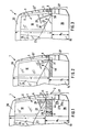
- FIGS. 1 to 5 show a stem arrangement 1 for a bus which has a parapet part 2 which runs on the front side below the windshield 12, 12 'or 12 "and extends laterally into the area of the side door 3.
- a supporting column 6 which usually surrounds the windshield and is usually referred to as the A-pillar.
- the stem arrangement also includes an A- which is arranged on both sides of the respective windshield 12, 12 'or 12' '. Columns 6 connected canopy 20.
- the storage space 13 in FIG. 1 has a height H 1
- the storage space 14 in the embodiment in FIG. 2 has a height H 2
- the storage space 15 has a height H 3 .
- This is due, for example, to the fact that the design according to FIG. 1 with the highest storage space is designed for an overland coach which requires a larger storage space, while the bus design according to FIG. 3, for example, only a city bus or the like. is.
- the stem arrangement 1 is now designed so that it can be adapted in a simple manner to the passenger compartment 21 and the storage space located underneath, which is designed differently in height.
- Fig. 1 and Fig. 4 both of which show the same stem for the bus version with the highest storage space with the height H 1 , it can be seen that the passenger compartment 21 is seated above the storage space 13, which in turn has a certain height dimension X having.
- the stem arrangement 1 is therefore designed for the corresponding height H 1 + x.
- the side door 3, which there emerges from the window 10 with the lower edge 22 rising obliquely to the rear is provided, which ends in the extension to the rear on the lower front corner 23 of the first window 24 of the passenger compartment 21.
- Side window 24 and side window 10 of the door are optically matched to one another in this way.
- the front corner 25 of the side window 10 of the door lies approximately on a horizontal line 9, which in the stem arrangement of FIG. 1 is adjacent to a separating area 4a, which has the height h and the meaning of which is still to be discussed.
- the lower door part 26, which delimits the door at the bottom sits below the separating area 4a of the side door 3.
- the A pillar or the support pillar 6 is arranged on the side of the windshield 12 and the separating area 4, the height of which corresponds to the height h of the separating area 4 a of the side door 3.
- the upper edge of the separating area 4 corresponds to the lower edge 11 of the windshield 12.
- the root 8 of the A-pillar 6 also adjoins the upper edge of the separating area 4.
- Below the separating area 4 is an area 27 of the parapet part 2, which consists of the three sub-sections 27a to 27c lying one below the other for stylistic reasons.
- the assignment of the passenger compartment 21 to the upper part of the door remains the same in this case, so that the lower edge 22 of the window 10 of the side door 3 continues to the lower front corner 23 of the first window 24 the passenger compartment 21 runs out.
- the storage space 15 here, however, only has the height H 3 , which here lies in front of the lower door part 26 and the lower front area 27 of the parapet part 2, which have remained the same as in the embodiment of FIGS. 1 and 4.
- an additional parapet part 30 is arranged in front of the windshield 12 ′, the upper edge of which the lower edge 11 of the windshield 12 "is aligned, which runs at the same height with respect to the road as is also the case with the embodiment of FIGS. 1 and 4.
- This parapet part 30 can additionally be placed on, it is of course also possible, as will be explained later, to take measures in the separating area 4 so that the parapet part 30 hatched in FIG. 3 is present in all versions and only the A- Column 6 moves accordingly and the windshield 12, 12 'or 12 "is correspondingly shorter.
- the separating regions 4 on the parapet part or 4a in the side door which are only indicated schematically in FIGS. 1 to 5, are each arranged in regions in which the corresponding support or body parts have a 0 drop. In these areas 4, 4a, it is therefore possible to shorten the components without the need for difficult adjustment work due to curved columns or the like. become necessary.
- FIG. 6 and 7 shows how the separating areas 4 and 4a can be realized in order to enable the desired adaptation of the stem to different storage space heights.
- the so-called A-pillar 6, which limits the windshield 12 laterally be made of two half-shells 6a, 6b stands, of which the half-shell 6a is the inner half-shell, 6b the outer half-shell, on which the hinges 32 for the side door 3 are attached.
- a seal 33 is provided for a tight seal between the A-pillar 6 and the side door 3.
- An intermediate size can also be realized analogously if the storage space 14, as shown in FIG. 2, has, for example, the height H 2 .
- the part 31 of the parapet part 2 protruding in front of the A-pillar 6 then becomes correspondingly smaller. It is crucial that the half-shells 6a, 6b of the A-pillar 6 and analogously the side parts of the door have the drop 0 in each of the separating areas 4 and 4a, so that removal of the corresponding components does not make any drop adjustment or other adjustment of the door or front parts necessary .
- the height of the driver's seat 28 and the steering wheel 29 are at the same height with respect to the lower edge 11 of the windshield 12, 12 ', 12''and at the same height from the roadway.
- the stem arrangement therefore allows the use of the same components despite different heights. It is particularly suitable for the serial production of vehicles of different installation space sizes.
- the passenger compartment 21 remains unchanged.
- the upper door part with the side window 10 and the lower door part 26 and the associated A-pillar 6 and the part 27 of the parapet part 2 also remain unchanged.
Landscapes
- Engineering & Computer Science (AREA)
- Chemical & Material Sciences (AREA)
- Combustion & Propulsion (AREA)
- Transportation (AREA)
- Mechanical Engineering (AREA)
- Body Structure For Vehicles (AREA)
Applications Claiming Priority (2)
| Application Number | Priority Date | Filing Date | Title |
|---|---|---|---|
| DE19853531525 DE3531525C1 (de) | 1985-09-04 | 1985-09-04 | Vorbauanordnung fuer Nutzfahrzeuge,insbesondere fuer Omnibusse |
| DE3531525 | 1985-09-04 |
Publications (3)
| Publication Number | Publication Date |
|---|---|
| EP0213624A2 true EP0213624A2 (fr) | 1987-03-11 |
| EP0213624A3 EP0213624A3 (en) | 1987-09-16 |
| EP0213624B1 EP0213624B1 (fr) | 1990-02-07 |
Family
ID=6280080
Family Applications (1)
| Application Number | Title | Priority Date | Filing Date |
|---|---|---|---|
| EP19860112017 Expired - Lifetime EP0213624B1 (fr) | 1985-09-04 | 1986-08-30 | Structure d'un avant-corps pour véhicules utilitaires, particulièrement pour autocars |
Country Status (5)
| Country | Link |
|---|---|
| EP (1) | EP0213624B1 (fr) |
| BR (1) | BR8604225A (fr) |
| DE (1) | DE3531525C1 (fr) |
| ES (1) | ES2001928A6 (fr) |
| HU (1) | HU197265B (fr) |
Families Citing this family (1)
| Publication number | Priority date | Publication date | Assignee | Title |
|---|---|---|---|---|
| IT1214261B (it) * | 1987-02-24 | 1990-01-10 | I R C A Ind Resistenze Corazza | Elemento scaldante per apparecchi elettrodomestici. |
Family Cites Families (1)
| Publication number | Priority date | Publication date | Assignee | Title |
|---|---|---|---|---|
| DE2712752A1 (de) * | 1977-03-23 | 1978-09-28 | Daimler Benz Ag | Wagenkasten fuer grossraumfahrzeuge, insbesondere omnibusse |
-
1985
- 1985-09-04 DE DE19853531525 patent/DE3531525C1/de not_active Expired
-
1986
- 1986-08-27 HU HU370486A patent/HU197265B/hu unknown
- 1986-08-30 EP EP19860112017 patent/EP0213624B1/fr not_active Expired - Lifetime
- 1986-09-03 ES ES8601595A patent/ES2001928A6/es not_active Expired
- 1986-09-03 BR BR8604225A patent/BR8604225A/pt not_active IP Right Cessation
Also Published As
| Publication number | Publication date |
|---|---|
| BR8604225A (pt) | 1987-04-28 |
| EP0213624B1 (fr) | 1990-02-07 |
| DE3531525C1 (de) | 1987-01-22 |
| EP0213624A3 (en) | 1987-09-16 |
| ES2001928A6 (es) | 1988-07-01 |
| HU197265B (en) | 1989-03-28 |
| HUT45719A (en) | 1988-08-29 |
Similar Documents
| Publication | Publication Date | Title |
|---|---|---|
| DE69301923T2 (de) | Querteil für ein armaturenbrett für ein kraftfahrzeug | |
| DE3810268C2 (fr) | ||
| EP0613798B1 (fr) | Porte de véhicule, notamment pour automobiles | |
| EP0563526B1 (fr) | Système de construction par gammes pour cabines de conducteur de camions | |
| EP0461345A1 (fr) | Carrosserie pour un véhicule automobile, en particulier pour une voiture de tourisme | |
| EP1911662B1 (fr) | Fond de caisse d'un véhicule et système de plate-forme | |
| DE29624410U1 (de) | Vorrichtung zum bündigen Verschließen einer Öffnung in der Karosserie eines Fahrzeuges | |
| DE102005044283A1 (de) | Kraftfahrzeugkarosserie mit einem Adapterträger für ein Dachmodul, Adapterträger hierfür, sowie Verfahren zu deren Herstellung | |
| DE69926186T2 (de) | Bodengruppe für Kraftfahrzeuge | |
| DE3622483A1 (de) | Stossfaenger fuer fahrzeuge | |
| DE2759029C2 (fr) | ||
| DE102010005834B4 (de) | Stützanordnung für eine Windschutzscheibe eines Personenkraftwagens | |
| DE3151405A1 (de) | Fahrzeugdach, insbesondere fuer personenkraftwagen | |
| DE3540814A1 (de) | Karosserie fuer personenkraftwagen und verfahren zur herstellung einer solchen karosserie | |
| DE8815885U1 (de) | Fahrzeugkarosserie | |
| EP3484735B1 (fr) | Procédé de fabrication d'un toit de véhicule, toit modulaire pour toit de véhicule et toit de véhicule pour véhicule à moteur | |
| EP0096846B1 (fr) | Carrosserie pour véhicules automobiles notamment pour voitures particulières et procédé de fabrication d'une telle carrosserie | |
| DE10332508A1 (de) | Fahrerhaus für ein Nutzfahrzeug | |
| DE4028327C2 (fr) | ||
| DE10302756B4 (de) | Tragstruktur für eine Kraftwagenkarosserie | |
| EP0213624B1 (fr) | Structure d'un avant-corps pour véhicules utilitaires, particulièrement pour autocars | |
| DE3024619A1 (de) | Hardtop fuer einen gelaendewagen | |
| DE19538457A1 (de) | Mehrkammerprofil | |
| DE4330014A1 (de) | Kraftfahrzeug, insbesondere Van | |
| DE10302755B4 (de) | Tragstruktur für eine Kraftwagenkarosserie |
Legal Events
| Date | Code | Title | Description |
|---|---|---|---|
| PUAI | Public reference made under article 153(3) epc to a published international application that has entered the european phase |
Free format text: ORIGINAL CODE: 0009012 |
|
| AK | Designated contracting states |
Kind code of ref document: A2 Designated state(s): BE FR GB IT NL |
|
| PUAL | Search report despatched |
Free format text: ORIGINAL CODE: 0009013 |
|
| AK | Designated contracting states |
Kind code of ref document: A3 Designated state(s): BE FR GB IT NL |
|
| 17P | Request for examination filed |
Effective date: 19870806 |
|
| 17Q | First examination report despatched |
Effective date: 19890630 |
|
| GRAA | (expected) grant |
Free format text: ORIGINAL CODE: 0009210 |
|
| ITF | It: translation for a ep patent filed | ||
| AK | Designated contracting states |
Kind code of ref document: B1 Designated state(s): BE FR GB IT NL |
|
| GBT | Gb: translation of ep patent filed (gb section 77(6)(a)/1977) | ||
| ET | Fr: translation filed | ||
| PLBE | No opposition filed within time limit |
Free format text: ORIGINAL CODE: 0009261 |
|
| STAA | Information on the status of an ep patent application or granted ep patent |
Free format text: STATUS: NO OPPOSITION FILED WITHIN TIME LIMIT |
|
| 26N | No opposition filed | ||
| ITTA | It: last paid annual fee | ||
| PGFP | Annual fee paid to national office [announced via postgrant information from national office to epo] |
Ref country code: FR Payment date: 19960814 Year of fee payment: 11 |
|
| PGFP | Annual fee paid to national office [announced via postgrant information from national office to epo] |
Ref country code: NL Payment date: 19960822 Year of fee payment: 11 Ref country code: BE Payment date: 19960822 Year of fee payment: 11 |
|
| PGFP | Annual fee paid to national office [announced via postgrant information from national office to epo] |
Ref country code: GB Payment date: 19970814 Year of fee payment: 12 |
|
| PG25 | Lapsed in a contracting state [announced via postgrant information from national office to epo] |
Ref country code: BE Free format text: LAPSE BECAUSE OF NON-PAYMENT OF DUE FEES Effective date: 19970831 |
|
| BERE | Be: lapsed |
Owner name: DAIMLER-BENZ A.G. Effective date: 19970831 |
|
| PG25 | Lapsed in a contracting state [announced via postgrant information from national office to epo] |
Ref country code: NL Free format text: LAPSE BECAUSE OF NON-PAYMENT OF DUE FEES Effective date: 19980301 |
|
| PG25 | Lapsed in a contracting state [announced via postgrant information from national office to epo] |
Ref country code: FR Free format text: LAPSE BECAUSE OF NON-PAYMENT OF DUE FEES Effective date: 19980430 |
|
| NLV4 | Nl: lapsed or anulled due to non-payment of the annual fee |
Effective date: 19980301 |
|
| REG | Reference to a national code |
Ref country code: FR Ref legal event code: ST |
|
| PG25 | Lapsed in a contracting state [announced via postgrant information from national office to epo] |
Ref country code: GB Free format text: LAPSE BECAUSE OF NON-PAYMENT OF DUE FEES Effective date: 19980830 |
|
| GBPC | Gb: european patent ceased through non-payment of renewal fee |
Effective date: 19980830 |
|
| PG25 | Lapsed in a contracting state [announced via postgrant information from national office to epo] |
Ref country code: IT Free format text: LAPSE BECAUSE OF NON-PAYMENT OF DUE FEES;WARNING: LAPSES OF ITALIAN PATENTS WITH EFFECTIVE DATE BEFORE 2007 MAY HAVE OCCURRED AT ANY TIME BEFORE 2007. THE CORRECT EFFECTIVE DATE MAY BE DIFFERENT FROM THE ONE RECORDED. Effective date: 20050830 |