EP0213505B1 - Pipe coupling - Google Patents
Pipe coupling Download PDFInfo
- Publication number
- EP0213505B1 EP0213505B1 EP86111285A EP86111285A EP0213505B1 EP 0213505 B1 EP0213505 B1 EP 0213505B1 EP 86111285 A EP86111285 A EP 86111285A EP 86111285 A EP86111285 A EP 86111285A EP 0213505 B1 EP0213505 B1 EP 0213505B1
- Authority
- EP
- European Patent Office
- Prior art keywords
- coupling
- pipe
- connection
- threads
- details
- Prior art date
- Legal status (The legal status is an assumption and is not a legal conclusion. Google has not performed a legal analysis and makes no representation as to the accuracy of the status listed.)
- Expired - Lifetime
Links
- 230000008878 coupling Effects 0.000 title claims abstract description 64
- 238000010168 coupling process Methods 0.000 title claims abstract description 64
- 238000005859 coupling reaction Methods 0.000 title claims abstract description 64
- 238000007789 sealing Methods 0.000 claims abstract description 20
- 238000006073 displacement reaction Methods 0.000 claims abstract description 3
- 239000000463 material Substances 0.000 claims description 9
- 210000002310 elbow joint Anatomy 0.000 claims description 2
- 230000003993 interaction Effects 0.000 claims description 2
- 230000006835 compression Effects 0.000 abstract description 5
- 238000007906 compression Methods 0.000 abstract description 5
- 230000002093 peripheral effect Effects 0.000 abstract 1
- 239000002184 metal Substances 0.000 description 2
- 210000000078 claw Anatomy 0.000 description 1
- 238000004519 manufacturing process Methods 0.000 description 1
- 229920003023 plastic Polymers 0.000 description 1
- 239000004033 plastic Substances 0.000 description 1
Images
Classifications
-
- F—MECHANICAL ENGINEERING; LIGHTING; HEATING; WEAPONS; BLASTING
- F16—ENGINEERING ELEMENTS AND UNITS; GENERAL MEASURES FOR PRODUCING AND MAINTAINING EFFECTIVE FUNCTIONING OF MACHINES OR INSTALLATIONS; THERMAL INSULATION IN GENERAL
- F16L—PIPES; JOINTS OR FITTINGS FOR PIPES; SUPPORTS FOR PIPES, CABLES OR PROTECTIVE TUBING; MEANS FOR THERMAL INSULATION IN GENERAL
- F16L19/00—Joints in which sealing surfaces are pressed together by means of a member, e.g. a swivel nut, screwed on, or into, one of the joint parts
- F16L19/06—Joints in which sealing surfaces are pressed together by means of a member, e.g. a swivel nut, screwed on, or into, one of the joint parts in which radial clamping is obtained by wedging action on non-deformed pipe ends
- F16L19/075—Joints in which sealing surfaces are pressed together by means of a member, e.g. a swivel nut, screwed on, or into, one of the joint parts in which radial clamping is obtained by wedging action on non-deformed pipe ends specially adapted for spigot-and-socket joints for pipes of the same diameter
-
- F—MECHANICAL ENGINEERING; LIGHTING; HEATING; WEAPONS; BLASTING
- F16—ENGINEERING ELEMENTS AND UNITS; GENERAL MEASURES FOR PRODUCING AND MAINTAINING EFFECTIVE FUNCTIONING OF MACHINES OR INSTALLATIONS; THERMAL INSULATION IN GENERAL
- F16L—PIPES; JOINTS OR FITTINGS FOR PIPES; SUPPORTS FOR PIPES, CABLES OR PROTECTIVE TUBING; MEANS FOR THERMAL INSULATION IN GENERAL
- F16L19/00—Joints in which sealing surfaces are pressed together by means of a member, e.g. a swivel nut, screwed on, or into, one of the joint parts
- F16L19/06—Joints in which sealing surfaces are pressed together by means of a member, e.g. a swivel nut, screwed on, or into, one of the joint parts in which radial clamping is obtained by wedging action on non-deformed pipe ends
- F16L19/062—Joints in which sealing surfaces are pressed together by means of a member, e.g. a swivel nut, screwed on, or into, one of the joint parts in which radial clamping is obtained by wedging action on non-deformed pipe ends specially adapted for use with attachments, e.g. reduction units, T-pieces, bends or the like
-
- F—MECHANICAL ENGINEERING; LIGHTING; HEATING; WEAPONS; BLASTING
- F16—ENGINEERING ELEMENTS AND UNITS; GENERAL MEASURES FOR PRODUCING AND MAINTAINING EFFECTIVE FUNCTIONING OF MACHINES OR INSTALLATIONS; THERMAL INSULATION IN GENERAL
- F16L—PIPES; JOINTS OR FITTINGS FOR PIPES; SUPPORTS FOR PIPES, CABLES OR PROTECTIVE TUBING; MEANS FOR THERMAL INSULATION IN GENERAL
- F16L19/00—Joints in which sealing surfaces are pressed together by means of a member, e.g. a swivel nut, screwed on, or into, one of the joint parts
- F16L19/06—Joints in which sealing surfaces are pressed together by means of a member, e.g. a swivel nut, screwed on, or into, one of the joint parts in which radial clamping is obtained by wedging action on non-deformed pipe ends
- F16L19/07—Joints in which sealing surfaces are pressed together by means of a member, e.g. a swivel nut, screwed on, or into, one of the joint parts in which radial clamping is obtained by wedging action on non-deformed pipe ends adapted for use in socket or sleeve connections
Definitions
- the present invention relates to a pipe coupling system, comprising different kinds of coupling details, such as pipe joints, elbows and Ts having threaded and rigid end portions.
- Coupling details of this kind are previously known through e.g. US-A-502.665, FR-A-1.242.421 and US-A-3.405.751. All of these known details must, however, be stocked for all the pipe dimensions on the market, to enable pipe connections, e.g. in the form of joints, adapters, tees, elbows and direct pipe connections in plastics and metal pipes.
- pipe connections e.g. in the form of joints, adapters, tees, elbows and direct pipe connections in plastics and metal pipes.
- a pipe coupling system distinguished in essentials by the fact that each of the details are formed in one piece and all end portions are provided with external and internal threads of uniform and constant pitch, as known per se, and with a guide surface for interaction with clamping and sealing means, and that the details are desinged in different sizes and thus adapted that the external threads of each deteil mate with the internal threads of the nearest in size bigger detail, and vice versa, and that each end of the different details is adapted for connection to pipes and tubes of at least three different kinds, viz.
- the internal and external threads on each end portion are mutually axially displaced about one half pitch to obtain more even thickness and increased strength of the material lying between the external and internal threads.
- said sealing and clamping means comprises a sealing sleeve portion which upon axial displacement against said guide surface is adapted to seal either directly against the pipe or against the bushing ring applied to the end of the pipe.
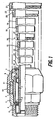
- Fig. 1 illustrates how a coupling in the inventive system may be used for connecting a plurality of differently dimensioned pipes of different materials.
- a clamping and sealing means is formed as two rings.
- One ring might be said to serve solely as a clamping ring 1, while the other ring serves as guide and sealing ring 2.
- the left-hand end of the guide and sealing ring 2 bears against the elastic seal 3, which in turn bears against the guiding and sealing surfaci 4 i.e., the step in the stepped bore of the connection coupling housing 5.
- bushes 7 and 8 which must be adapted to each pipe dimension connected to the coupling housing 5.
- the latter also accommodates the nut 9 having an internal thread, which is shown here solely to demonstrate that the coupling may also be used in the case where the dimension difference between coupling and pipe is considerable.
- the coupling housing 5 is threaded both on its exterior 10 and on its interior 11, and in the case illustrated in Fig. 1 the connection could also be made using a nut wish an external thread.
- the guiding and sealing ring 2 coacts with the guide flange 12 of the nut 9, and it is correspondingly provided with eloping guide surfaces which are pressed against guide surfaces on the clamping ring 1 when the nut 9 is screwed in, thus pressing the clamping ring 1 against the circumference of the pipe 6.
- the clamping ring 1 may be provided wing ridges which give a better grip on the pipe surface.
- the coupling may thus be utilized for pipes of other dimensions than that of the pipe 6 illustrated.
- the same clamping and sealing means may be utilized for all pipes 6,13-19. However, pipes 6, 13-18 need specially adapted bushes.
- the pipe 17 is a metal pipe with a threadad end on which is mounted a locking ring 16, adapted to the pipe seating in the coupling housing 5.
- the pipe 20 may be threaded directly on to the internal thread 11 of the coupling housing 5, while the pipe 21, which has the greatest diameter, may be connected with the aid of a threaded coupling ring 22.
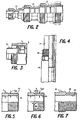
- the clamping ring 1 illustrated in Fig.1 can be realized in different ways, depending on the material from which the inserted pipe is made.
- Fig. 2 illustrates three coupling housings 23,24,and 25, all of which are threaded externally and internally at each connection end.
- the first housing 23 is for a so-called adapter, going from a small to a larger diameter, and can thus connect to a straight- through couplinghousing 24 which can also serve as an adapter coupling, since the right-hand side may be utilized, the latter being screwed into the largest coupling housing 25, where full lines depict a straight-through coupling and dashed lines an adapter coupling.
- the figure is thus an illustration of the coupling possibilities available when external and internal threads are used according to the inventive system.
- Fig. 3 illustrates an example of a connection with clamping and sealing means comprising a ring 1a provided with claws, which are acted on by a clamping and sealing ring 2a formed with a cuneformed tip which will be pressed against the sealing surface 4 (Fig. 1) when the nut 9 is screwed in, thus to translate the axial compression forces into radial compression forces against either the bushing ring 7 (Fig. 1) or directly against the pipe 19.
- Fig. 4 illustrates the use of a coupling housing 26, which is provided with external and internal threads and can therefore also be used as a coupling between pipes 27 and 28 of different diameters.
- Figs. 5 and 6 are cross sections of such double-threaded details as coupling housings or nuts.
- Fig. 5 illustrates the external thread 29 and internal thread 30 disposed directly opposite each other, such that the threaded part is given dimension variations lying between the material thickness t and a least thickness t min at the roots of the threads.
- the strength of the threaded portion will of course be determined by the least thickness t min .
- the threads have been mutually displaced half a pitch, resulting in that the material thickness in the theraded portion has a constant thickness t med lying between t med and t. Strength has thus been substantially increased in the threaded portion, signifying that the material thickness t for a given requirement of least strength of the thread may be reduced, which means of course that both weight and material costs are reduced.
- Fig. 7 illustrates an embodiment having a thread 31 for the locking nut. This thread has considerably less pitch than the pipe thread 29 which facilitates tightening the locking nut.
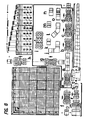
- Fig. 8 illustrates with the aid of tables and a coupling schedule the assembly of a pipe coupling system in accordance with the invention, intended to cover all the pipe dimensions on the market.
- Some of these dimemsions have been numbered from 1 to 37 in a coordinate table, where the numeral l denotes the largest and the numeral 37 the smallest dimension.
- the intersection point for the pipe dimensions which are to be coupled denotes the coordinates for the square representing the coupling in question.
- the coordinate table there are also symbols in the form of circles denoting what inventive coupling corresponds to the different pipe dimensions. Each symbol covers a given number of dimension numbers and the intersections between the symbols form fields, which have been indecated in the table by double lines. The number of squares thus denote how many pipe dimensions can be connected by one pipe coupling.
- the full lines in the coordinate table show the coupling facilities for pipe diameters in the diameter interval 17-25.
- This interval has been symbolized by a filled circle, and the corresponding field has been given two filled circles which are to be found in the key and represent a pipe coupling with two connections of the same dimension.
- This dimemsion is similarly framed by full lines and represented by a filled circle.
- pipes in the dimension interval 17-25 may optionally be coupled together.
- Suitable inner bushes of the type described in conjunction with Fig. 1 are used. Examples of such bushes are also depicted by the details k and m.
- the different accessories to a coupling which are identified by two filled circles have been marked, as indicated in the table, by an unfilled circle with a filled inner circle.
- These details may consist of e.g. a T as detail a, or different elbows as details j or l.
- the elbows pr Ts have three alternative connection possibilities at either end. If the pipe dimensions fall outside the full lined area in the coordinate table, for instance when connecting two pipes No 20 and No 30, an adapter coupling is utilized as appears from detail c designated with the symbols filled circle, and filled circle with an unfilled inner square.
- a further embodiment appears from the detail d, for instance for connection between pipes No. 20 and No.35.
- a pipe coupling system according to the invention privides a great number of different coupling alternatives with a minimum of details in order to realize all these joints.
- the costs for stock keeping can consequently be considerably reduced, which in hitherto known systems has involved increased economical stresses on both manufacturers and dealers.
Landscapes
- Engineering & Computer Science (AREA)
- General Engineering & Computer Science (AREA)
- Mechanical Engineering (AREA)
- Quick-Acting Or Multi-Walled Pipe Joints (AREA)
- Supports For Pipes And Cables (AREA)
- Joints Allowing Movement (AREA)
- Paper (AREA)
- Mutual Connection Of Rods And Tubes (AREA)
- Non-Disconnectible Joints And Screw-Threaded Joints (AREA)
- Valve Device For Special Equipments (AREA)
- Pulleys (AREA)
- Mechanical Operated Clutches (AREA)
- Optical Head (AREA)
- Mechanical Coupling Of Light Guides (AREA)
- Semiconductor Lasers (AREA)
- Medicines Containing Material From Animals Or Micro-Organisms (AREA)
- Medicines That Contain Protein Lipid Enzymes And Other Medicines (AREA)
- Branch Pipes, Bends, And The Like (AREA)
Priority Applications (1)
| Application Number | Priority Date | Filing Date | Title |
|---|---|---|---|
| AT86111285T ATE90145T1 (de) | 1982-08-11 | 1983-08-11 | Rohrverbindung. |
Applications Claiming Priority (2)
| Application Number | Priority Date | Filing Date | Title |
|---|---|---|---|
| SE8204648 | 1982-08-11 | ||
| SE8204648A SE8204648D0 (sv) | 1982-08-11 | 1982-08-11 | Rorkoppling |
Related Parent Applications (2)
| Application Number | Title | Priority Date | Filing Date |
|---|---|---|---|
| EP83902543A Division EP0131576A1 (en) | 1982-08-11 | 1983-08-11 | Pipe coupling |
| EP83902543.4 Division | 1984-03-07 |
Publications (3)
| Publication Number | Publication Date |
|---|---|
| EP0213505A2 EP0213505A2 (en) | 1987-03-11 |
| EP0213505A3 EP0213505A3 (en) | 1987-04-15 |
| EP0213505B1 true EP0213505B1 (en) | 1993-06-02 |
Family
ID=20347513
Family Applications (4)
| Application Number | Title | Priority Date | Filing Date |
|---|---|---|---|
| EP86111285A Expired - Lifetime EP0213505B1 (en) | 1982-08-11 | 1983-08-11 | Pipe coupling |
| EP83902543A Ceased EP0131576A1 (en) | 1982-08-11 | 1983-08-11 | Pipe coupling |
| EP86111286A Expired - Lifetime EP0212587B1 (en) | 1982-08-11 | 1983-08-11 | Pipe coupling |
| EP86111284A Withdrawn EP0212586A3 (en) | 1982-08-11 | 1983-08-11 | Pipe coupling |
Family Applications After (3)
| Application Number | Title | Priority Date | Filing Date |
|---|---|---|---|
| EP83902543A Ceased EP0131576A1 (en) | 1982-08-11 | 1983-08-11 | Pipe coupling |
| EP86111286A Expired - Lifetime EP0212587B1 (en) | 1982-08-11 | 1983-08-11 | Pipe coupling |
| EP86111284A Withdrawn EP0212586A3 (en) | 1982-08-11 | 1983-08-11 | Pipe coupling |
Country Status (12)
| Country | Link |
|---|---|
| US (1) | US4798404A (enExample) |
| EP (4) | EP0213505B1 (enExample) |
| JP (1) | JPS59501418A (enExample) |
| AT (2) | ATE90145T1 (enExample) |
| AU (4) | AU1828483A (enExample) |
| DE (2) | DE3382690T2 (enExample) |
| DK (1) | DK171684A (enExample) |
| FI (1) | FI843372A7 (enExample) |
| HU (1) | HUT35359A (enExample) |
| NO (1) | NO841413L (enExample) |
| SE (1) | SE8204648D0 (enExample) |
| WO (1) | WO1984000796A1 (enExample) |
Families Citing this family (48)
| Publication number | Priority date | Publication date | Assignee | Title |
|---|---|---|---|---|
| CA1311778C (en) * | 1988-05-12 | 1992-12-22 | Anthony L. Reese | Compression coupling |
| JP2677291B2 (ja) * | 1988-09-14 | 1997-11-17 | ブリヂストンフローテック株式会社 | 管継手 |
| GB8830202D0 (en) * | 1988-12-23 | 1989-02-22 | Parkfield Group Plc | Pipe coupling |
| US4934745A (en) * | 1989-08-14 | 1990-06-19 | Senninger Irrigation, Inc. | Flexible hose coupling |
| SE466813B (sv) * | 1990-02-15 | 1992-04-06 | Gambro Dialysatoren | Anvaendning av en nippel, som aer avsedd att bilda en del av en s k hansen-koppling |
| DE4227080A1 (de) * | 1992-08-17 | 1994-02-24 | Hummel Anton Verwaltung | Klemmverschraubung für längliche Körper, insbesondere für Rohre, Kabel, Schläuche oder dergleichen |
| CN1095805A (zh) * | 1992-11-30 | 1994-11-30 | 麦卡伯工业有限公司 | 一种固定装置 |
| DE4403702C2 (de) * | 1993-08-18 | 1996-03-28 | Hummel Anton Verwaltung | Klemmverschraubung mit beidseits beaufschlagtem Klemmring |
| WO1999032821A1 (en) * | 1997-12-23 | 1999-07-01 | Woong Jin Coway Co Ltd | Piping joint and integrated valve with it |
| US6161874A (en) * | 1999-04-01 | 2000-12-19 | Formosa Saint Jose Corp. | Water spray hose rolling device |
| EP1117940B1 (de) * | 1999-08-03 | 2004-10-27 | Weber-Stettler, Margrit | Gewindestange und gewindestangenanordnung |
| US6354637B1 (en) * | 2000-03-22 | 2002-03-12 | Coflex S.A. De C.V. | Adapter for connector and valves |
| US7438326B1 (en) * | 2000-08-31 | 2008-10-21 | Tuf-Tite, Inc. | Tee baffle for use at inlet or outlet of septic and other on-site waste disposal systems |
| US7066496B2 (en) | 2001-02-06 | 2006-06-27 | Swagelok Company | Fitting with separable gripping device for pipe and tube |
| KR20080091251A (ko) | 2001-02-06 | 2008-10-09 | 스와겔로크 컴패니 | 내부 풀업 표시를 갖는 이음쇠 |
| US7416225B2 (en) | 2001-02-06 | 2008-08-26 | Swagelok Company | Fitting for metal pipe and tubing |
| CN1297771C (zh) | 2001-02-06 | 2007-01-31 | 斯瓦戈洛克公司 | 一种不锈钢管管接头 |
| US7407196B2 (en) | 2003-08-06 | 2008-08-05 | Swagelok Company | Tube fitting with separable tube gripping device |
| DE10114854C1 (de) * | 2001-03-26 | 2002-11-28 | Hansa Metallwerke Ag | Sanitäre Auslaufarmatur |
| US6527303B2 (en) * | 2001-06-04 | 2003-03-04 | Shimano Inc. | Hydraulic hose assembly for bicycle |
| US7431351B2 (en) * | 2002-04-26 | 2008-10-07 | Russell Larry R | Pressure-containing tubular connections for remote operation |
| NL1027253C2 (nl) * | 2004-10-14 | 2006-04-19 | Wavin Bv | Buiskoppeling. |
| US8852167B2 (en) | 2005-12-01 | 2014-10-07 | Bayer Medical Care Inc. | Medical connector |
| US20080267709A1 (en) * | 2007-04-25 | 2008-10-30 | Terry Theophilus B | Method and apparatus for coupling drainage units |
| TWI432664B (zh) * | 2007-09-10 | 2014-04-01 | Omega Flex Inc | 使用於管路圍阻系統的接頭 |
| US20090230678A1 (en) * | 2008-03-14 | 2009-09-17 | Krohn Kenneth P | Compression fitting adjustment system |
| CN104587552B (zh) | 2008-06-06 | 2017-11-14 | 拜耳医药保健有限公司 | 用于向患者递送流体注射药丸以及处理有害流体的装置和方法 |
| US10215315B2 (en) | 2008-09-05 | 2019-02-26 | Parker-Hannifin Corporation | Tube compression fitting and flared fitting used with connection body and method of making same |
| US20120326439A1 (en) * | 2010-01-21 | 2012-12-27 | Automatic Switch Company | Valve and Other Connections |
| US8925976B2 (en) * | 2010-03-02 | 2015-01-06 | Omega Flex, Inc. | Flanged fitting for use with tubing containment system |
| US8328241B1 (en) | 2011-07-27 | 2012-12-11 | Duane D. Robertson | Clampless fitting for plastic pipes |
| US9125976B2 (en) | 2012-06-07 | 2015-09-08 | Bayer Medical Care Inc. | Shield adapters |
| US9393441B2 (en) | 2012-06-07 | 2016-07-19 | Bayer Healthcare Llc | Radiopharmaceutical delivery and tube management system |
| US9889288B2 (en) | 2012-06-07 | 2018-02-13 | Bayer Healthcare Llc | Tubing connectors |
| GB2504687A (en) * | 2012-08-06 | 2014-02-12 | Magma Global Ltd | A pipe assembly including a composite pipe |
| US9267689B2 (en) | 2013-03-04 | 2016-02-23 | Siemens Aktiengesellschaft | Combustor apparatus in a gas turbine engine |
| US9726309B1 (en) * | 2013-03-13 | 2017-08-08 | Mercury Plastics, Inc. | Tube connection nut and ferrule assembly |
| US9359838B2 (en) * | 2013-03-15 | 2016-06-07 | Vallourec Tube-Alloy, Llc. | Two-piece connection lift system and method |
| US9322558B2 (en) | 2013-06-27 | 2016-04-26 | Siemens Aktiengesellschaft | Combustor apparatus in a gas turbine engine |
| DE102014200674A1 (de) * | 2014-01-16 | 2015-07-16 | Zf Friedrichshafen Ag | Anschlussstück für ein Pitchrohr |
| CA2967293A1 (en) | 2014-05-09 | 2015-11-12 | Swagelok Company | Conduit fitting with components adapted for facilitating assembly |
| USD772383S1 (en) * | 2015-05-18 | 2016-11-22 | KMG Products, LLC | Double nut zero loss pipe union |
| EP3433522B1 (en) | 2016-03-23 | 2023-06-21 | Swagelok Company | Conduit fitting with stroke resisting features |
| BR112018073573B1 (pt) * | 2016-05-19 | 2023-05-16 | Control Flow, Inc | Equipamento vedador metal-metal de poço |
| US10295094B2 (en) * | 2016-06-08 | 2019-05-21 | Atkore Steel Components, Inc. | Conduit body with super fitting |
| US11187362B2 (en) * | 2016-06-14 | 2021-11-30 | Acorn Engineering Company | Conduit connector assembly |
| US10871247B2 (en) * | 2016-09-29 | 2020-12-22 | Hubbell Incorporated | Compression couplings |
| US11125028B2 (en) * | 2018-05-31 | 2021-09-21 | ProTorque Connection Technologies, Ltd. | Tubular lift ring |
Citations (1)
| Publication number | Priority date | Publication date | Assignee | Title |
|---|---|---|---|---|
| US502665A (en) * | 1893-08-01 | Samuel m |
Family Cites Families (47)
| Publication number | Priority date | Publication date | Assignee | Title |
|---|---|---|---|---|
| US2172532A (en) * | 1939-09-12 | Hose connection and method of | ||
| US500412A (en) * | 1893-06-27 | Pipe-fitting | ||
| US640183A (en) * | 1899-04-07 | 1900-01-02 | Solomon R Dresser | Friction pipe-coupling. |
| US747152A (en) * | 1901-11-15 | 1903-12-15 | Draper Mfg Co | Combined universal-joint pipe coupling and plug. |
| US1665346A (en) * | 1926-06-28 | 1928-04-10 | Harry W Clarke | Pipe connection |
| US2301280A (en) * | 1941-10-23 | 1942-11-10 | Chicago Forging & Mfg Co | Sealing means |
| US2405822A (en) * | 1943-02-26 | 1946-08-13 | Imp Brass Mfg Co | Sealed flexible coupling |
| GB588902A (en) * | 1945-03-09 | 1947-06-05 | Tube Patents Ltd | Improvements in or relating to a method of and means for coupling together pipes, tubular bodies and the like |
| US2434846A (en) * | 1947-03-01 | 1948-01-20 | John J Hagan | Pipe coupling for faucet connections |
| US2547318A (en) * | 1948-11-15 | 1951-04-03 | Harry E Karr | Tube and pipe fitting |
| US2943871A (en) * | 1956-10-25 | 1960-07-05 | Paul D Wurzburger | Tube coupling with deformable pipe gripping cutting means |
| US2936014A (en) * | 1957-07-24 | 1960-05-10 | Robert A Kraus | Resilient insert constricted to smaller diameter upon insertion in base member thereupon expanded to greater diameter to afford a friction lock |
| US3074747A (en) * | 1958-09-08 | 1963-01-22 | Joslyn Mfg & Supply Co | Coupling nut assembly |
| FR1246929A (fr) * | 1959-10-16 | 1960-11-25 | Fourrure isolante servant d'élément intermédiaire de liaison entre des pièces mécaniques | |
| FR1242421A (fr) * | 1959-10-30 | 1960-09-30 | Raccord | |
| US3074746A (en) * | 1959-11-16 | 1963-01-22 | Sidney J Shames | Jaw-type expansion adapter for fluid conduits |
| US3194592A (en) * | 1962-08-16 | 1965-07-13 | Pittsburgh Pipe And Coupling C | Coupling nut assembly |
| US3275350A (en) * | 1964-06-25 | 1966-09-27 | Imp Eastman Corp | Fitting |
| DE1284753B (de) * | 1964-11-25 | 1968-12-05 | Johannes Schaefer Kg Vorm Stet | Rohrverschraubung fuer Kunststoffrohre |
| DE1540167C3 (de) * | 1965-06-04 | 1974-10-03 | Micro-Electric Ag, Zuerich (Schweiz) | Cermet-Widerstandsschicht für ein Potentiometer |
| US3405751A (en) * | 1966-07-15 | 1968-10-15 | Thompson Wendell L | Element having continuous thread, portion of thread being longitudinally variable inlength |
| US3434745A (en) * | 1967-04-13 | 1969-03-25 | Smith Corp A O | Pipe coupling having a split ring locking means |
| US3484123A (en) * | 1968-04-18 | 1969-12-16 | Boeing Co | Reuseable flareless tube coupling |
| DE1952905A1 (de) * | 1969-10-21 | 1971-04-29 | Hellmut Schoeler | Gewindehuelse |
| DE2111568A1 (de) * | 1971-03-10 | 1972-09-28 | Georg Seiler | Zug- und Schubsicherung fuer Schraubmuffen-Verbindungen von Rohren |
| NL7211204A (enExample) * | 1972-08-16 | 1974-02-19 | ||
| DE2316531C3 (de) * | 1973-04-03 | 1978-06-15 | Mannesmannroehren-Werke Ag, 4000 Duesseldorf | Klemmring-Rohrverschraubung |
| US3938240A (en) * | 1973-10-24 | 1976-02-17 | Robert Stuart Holden | Methods of providing a tube with a thread ring |
| JPS5441124B2 (enExample) * | 1974-02-01 | 1979-12-06 | ||
| DE2426234C2 (de) * | 1974-05-29 | 1985-04-04 | Allstar Verbrauchsgüter GmbH & Co KG, 6000 Frankfurt | Verbindungsstück aus Kunststoff oder Metall zum lösbaren Anschluß von Rohren mit unterschiedlichen Durchmessern |
| US4019762A (en) * | 1974-08-27 | 1977-04-26 | I-T-E Imperial Corporation | Raintight connector for electrical conduit |
| US3972547A (en) * | 1974-11-21 | 1976-08-03 | Zenzo Ono | Locking and nonseal joint device |
| JPS5243122A (en) * | 1975-10-02 | 1977-04-04 | Hiroshi Hojo | Joining structure between a coupling and pipe |
| US4059297A (en) * | 1976-03-08 | 1977-11-22 | Parker-Hannifin Corporation | Tube coupling |
| FR2379009A1 (fr) * | 1977-01-28 | 1978-08-25 | Banides & Debeaurain Ets | Raccord pour canalisations semi-rigides |
| JPS5316916A (en) * | 1977-01-31 | 1978-02-16 | Mitsubishi Chem Ind Ltd | Coupling for pipe made of synthetic resin |
| FR2383385A1 (fr) * | 1977-03-09 | 1978-10-06 | Legris France Sa | Perfectionnement aux raccords rapides pour tuyaux flexibles renforces multicouches pour fluides |
| GB1530205A (en) * | 1977-07-20 | 1978-10-25 | Fischer Castings Ltd G | Pipe coupling |
| NZ188004A (en) * | 1977-08-05 | 1982-02-23 | Philmac Pty Ltd | Polymeric pipe fitting locking ring maintains constant pressure on deformable seal |
| US4257629A (en) * | 1978-05-01 | 1981-03-24 | Rain Bird Sprinkler Mfg. Corp. | Flexible conduit repair coupling |
| FR2438224A1 (fr) * | 1978-10-02 | 1980-04-30 | Viault Sa G | Dispositif de raccordement pour element tubulaire |
| US4235461A (en) * | 1978-10-31 | 1980-11-25 | Normark Olov M | Coupling between mechanical elements |
| FR2461186A1 (fr) * | 1979-07-06 | 1981-01-30 | Legris | Perfectionnement aux raccords pour tuyauteries notamment pour tuyauteries de fluides a haute pression |
| NL8005711A (nl) * | 1979-10-18 | 1981-04-22 | Tungum Hydraulics Ltd | Pijpkoppeling met axiaal bewegende delen. |
| FR2479406B1 (fr) * | 1980-03-28 | 1985-08-23 | Legris | Raccords instantanes pour tubes nus et lisses |
| EP0057223A1 (en) * | 1980-08-11 | 1982-08-11 | STEENGRACHT VAN MOYLAND, Jan | Tube screws and methods of penetrating materials using tube screws |
| DE3333866C2 (de) * | 1983-09-20 | 1986-10-16 | Ermeto Armaturen Gmbh, 4800 Bielefeld | Dichtungsring für Rohrverbindungen und Verfahren zur Montage einer Rohrverbindung unter Verwendung eines solchen Dichtungsringes |
-
1982
- 1982-08-11 SE SE8204648A patent/SE8204648D0/xx unknown
-
1983
- 1983-08-11 AT AT86111285T patent/ATE90145T1/de not_active IP Right Cessation
- 1983-08-11 AU AU18284/83A patent/AU1828483A/en not_active Abandoned
- 1983-08-11 US US06/598,327 patent/US4798404A/en not_active Expired - Fee Related
- 1983-08-11 DE DE86111285T patent/DE3382690T2/de not_active Expired - Fee Related
- 1983-08-11 EP EP86111285A patent/EP0213505B1/en not_active Expired - Lifetime
- 1983-08-11 DE DE8686111286T patent/DE3381800D1/de not_active Expired - Lifetime
- 1983-08-11 JP JP58502627A patent/JPS59501418A/ja active Granted
- 1983-08-11 AT AT86111286T patent/ATE55465T1/de not_active IP Right Cessation
- 1983-08-11 EP EP83902543A patent/EP0131576A1/en not_active Ceased
- 1983-08-11 EP EP86111286A patent/EP0212587B1/en not_active Expired - Lifetime
- 1983-08-11 HU HU833284A patent/HUT35359A/hu unknown
- 1983-08-11 EP EP86111284A patent/EP0212586A3/en not_active Withdrawn
- 1983-08-11 WO PCT/SE1983/000288 patent/WO1984000796A1/en not_active Ceased
-
1984
- 1984-03-28 DK DK171684A patent/DK171684A/da active IP Right Grant
- 1984-04-10 NO NO841413A patent/NO841413L/no unknown
- 1984-08-27 FI FI843372A patent/FI843372A7/fi not_active Application Discontinuation
-
1988
- 1988-03-21 AU AU13333/88A patent/AU1333388A/en not_active Abandoned
- 1988-03-21 AU AU13334/88A patent/AU1333488A/en not_active Abandoned
-
1991
- 1991-09-05 AU AU83680/91A patent/AU8368091A/en not_active Abandoned
Patent Citations (1)
| Publication number | Priority date | Publication date | Assignee | Title |
|---|---|---|---|---|
| US502665A (en) * | 1893-08-01 | Samuel m |
Also Published As
| Publication number | Publication date |
|---|---|
| WO1984000796A1 (en) | 1984-03-01 |
| EP0212587A3 (en) | 1987-04-15 |
| DK171684D0 (da) | 1984-03-28 |
| EP0212586A3 (en) | 1987-04-15 |
| DE3382690T2 (de) | 1994-01-20 |
| DE3381800D1 (de) | 1990-09-13 |
| ATE55465T1 (de) | 1990-08-15 |
| FI843372A0 (fi) | 1984-08-27 |
| US4798404A (en) | 1989-01-17 |
| EP0213505A3 (en) | 1987-04-15 |
| AU1333388A (en) | 1988-06-23 |
| SE8204648D0 (sv) | 1982-08-11 |
| DE3382690D1 (de) | 1993-07-08 |
| ATE90145T1 (de) | 1993-06-15 |
| NO841413L (no) | 1984-04-10 |
| DK171684A (da) | 1984-03-28 |
| AU1828483A (en) | 1984-03-07 |
| FI843372A7 (fi) | 1984-08-27 |
| EP0212586A2 (en) | 1987-03-04 |
| EP0213505A2 (en) | 1987-03-11 |
| EP0212587A2 (en) | 1987-03-04 |
| EP0212587B1 (en) | 1990-08-08 |
| JPS59501418A (ja) | 1984-08-09 |
| JPH0556438B2 (enExample) | 1993-08-19 |
| HUT35359A (en) | 1985-06-28 |
| AU1333488A (en) | 1988-06-23 |
| EP0131576A1 (en) | 1985-01-23 |
| AU8368091A (en) | 1991-11-14 |
Similar Documents
| Publication | Publication Date | Title |
|---|---|---|
| EP0213505B1 (en) | Pipe coupling | |
| US4226164A (en) | Split threaded coupling nut | |
| US5131632A (en) | Quick coupling pipe connecting structure with body-tapered sleeve | |
| US5403043A (en) | Quick connect pipe coupling | |
| US4136896A (en) | Flareless tube fitting for 37° adapter | |
| US5188401A (en) | Pipe coupling with interlocked and segmented grip ring | |
| US4483555A (en) | Pipe coupling | |
| US3381982A (en) | Plastic fitting assembly | |
| EP1511958B1 (en) | Pipe coupling | |
| GB2200702A (en) | Coupling plain pipe ends | |
| JPH04312280A (ja) | 空気圧装置のための雄ねじ及び雌ねじ | |
| US3563574A (en) | Coupling for plastic pipe | |
| GB1568669A (en) | Pipe connectors | |
| EP0418434A1 (en) | Adjustable connection apparatus | |
| US3809412A (en) | Pipe couplings | |
| EP0086509A1 (en) | Unitary clamp action fitting | |
| US4822082A (en) | Tube connector | |
| US10323777B2 (en) | Pipe coupling fitting with internal spacer sleeve | |
| US3368831A (en) | Coupling device | |
| EP0531068A2 (en) | Pipe couplings | |
| US4786089A (en) | Automatically locking tubing coupler | |
| EP0939871A1 (en) | Device on a conduit end and arrangement for joining conduits | |
| US3486774A (en) | Piping | |
| GB2056607A (en) | A pipe connection joint | |
| US1213132A (en) | Pipe-coupling. |
Legal Events
| Date | Code | Title | Description |
|---|---|---|---|
| PUAI | Public reference made under article 153(3) epc to a published international application that has entered the european phase |
Free format text: ORIGINAL CODE: 0009012 |
|
| PUAL | Search report despatched |
Free format text: ORIGINAL CODE: 0009013 |
|
| 17P | Request for examination filed |
Effective date: 19860908 |
|
| AC | Divisional application: reference to earlier application |
Ref document number: 131576 Country of ref document: EP |
|
| AK | Designated contracting states |
Kind code of ref document: A2 Designated state(s): AT BE CH DE FR GB LI NL SE |
|
| AK | Designated contracting states |
Kind code of ref document: A3 Designated state(s): AT BE CH DE FR GB LI NL SE |
|
| 17Q | First examination report despatched |
Effective date: 19871214 |
|
| RAP1 | Party data changed (applicant data changed or rights of an application transferred) |
Owner name: IWANICKI, ANDRZEJ, TOMASZ |
|
| GRAA | (expected) grant |
Free format text: ORIGINAL CODE: 0009210 |
|
| AC | Divisional application: reference to earlier application |
Ref document number: 131576 Country of ref document: EP |
|
| AK | Designated contracting states |
Kind code of ref document: B1 Designated state(s): AT BE CH DE FR GB LI NL SE |
|
| PG25 | Lapsed in a contracting state [announced via postgrant information from national office to epo] |
Ref country code: LI Effective date: 19930602 Ref country code: CH Effective date: 19930602 |
|
| REF | Corresponds to: |
Ref document number: 90145 Country of ref document: AT Date of ref document: 19930615 Kind code of ref document: T |
|
| REF | Corresponds to: |
Ref document number: 3382690 Country of ref document: DE Date of ref document: 19930708 |
|
| PG25 | Lapsed in a contracting state [announced via postgrant information from national office to epo] |
Ref country code: SE Effective date: 19930812 |
|
| PG25 | Lapsed in a contracting state [announced via postgrant information from national office to epo] |
Ref country code: GB Effective date: 19930902 |
|
| REG | Reference to a national code |
Ref country code: CH Ref legal event code: PL |
|
| ET | Fr: translation filed | ||
| PLBE | No opposition filed within time limit |
Free format text: ORIGINAL CODE: 0009261 |
|
| STAA | Information on the status of an ep patent application or granted ep patent |
Free format text: STATUS: NO OPPOSITION FILED WITHIN TIME LIMIT |
|
| GBPC | Gb: european patent ceased through non-payment of renewal fee |
Effective date: 19930902 |
|
| REG | Reference to a national code |
Ref country code: GB Ref legal event code: 732E |
|
| 26N | No opposition filed | ||
| EUG | Se: european patent has lapsed |
Ref document number: 86111285.2 Effective date: 19940310 |
|
| NLS | Nl: assignments of ep-patents |
Owner name: GIOVANNI GOZZO AB TE STOCKHOLM, ZWEDEN. |
|
| REG | Reference to a national code |
Ref country code: GB Ref legal event code: 728C |
|
| REG | Reference to a national code |
Ref country code: FR Ref legal event code: TP |
|
| REG | Reference to a national code |
Ref country code: GB Ref legal event code: 728R |
|
| BECA | Be: change of holder's address |
Free format text: 950323 *ADVOKAT GIOVANNI GOZZO A.B.:NYBROKAJEN 7, 11 48 STOCKHOLM |
|
| PGFP | Annual fee paid to national office [announced via postgrant information from national office to epo] |
Ref country code: AT Payment date: 19960829 Year of fee payment: 14 |
|
| PGFP | Annual fee paid to national office [announced via postgrant information from national office to epo] |
Ref country code: NL Payment date: 19960831 Year of fee payment: 14 |
|
| PGFP | Annual fee paid to national office [announced via postgrant information from national office to epo] |
Ref country code: BE Payment date: 19961009 Year of fee payment: 14 |
|
| PG25 | Lapsed in a contracting state [announced via postgrant information from national office to epo] |
Ref country code: AT Free format text: LAPSE BECAUSE OF NON-PAYMENT OF DUE FEES Effective date: 19970811 |
|
| PG25 | Lapsed in a contracting state [announced via postgrant information from national office to epo] |
Ref country code: BE Free format text: LAPSE BECAUSE OF NON-PAYMENT OF DUE FEES Effective date: 19970831 |
|
| PGFP | Annual fee paid to national office [announced via postgrant information from national office to epo] |
Ref country code: FR Payment date: 19980227 Year of fee payment: 15 |
|
| BERE | Be: lapsed |
Owner name: ADVOKAT GIOVANNI GOZZO A.B. Effective date: 19970831 |
|
| PG25 | Lapsed in a contracting state [announced via postgrant information from national office to epo] |
Ref country code: NL Free format text: LAPSE BECAUSE OF NON-PAYMENT OF DUE FEES Effective date: 19980301 |
|
| NLV4 | Nl: lapsed or anulled due to non-payment of the annual fee |
Effective date: 19980301 |
|
| PGFP | Annual fee paid to national office [announced via postgrant information from national office to epo] |
Ref country code: DE Payment date: 19981020 Year of fee payment: 16 |
|
| PG25 | Lapsed in a contracting state [announced via postgrant information from national office to epo] |
Ref country code: FR Free format text: LAPSE BECAUSE OF NON-PAYMENT OF DUE FEES Effective date: 19990430 |
|
| REG | Reference to a national code |
Ref country code: FR Ref legal event code: ST |
|
| PG25 | Lapsed in a contracting state [announced via postgrant information from national office to epo] |
Ref country code: DE Free format text: LAPSE BECAUSE OF NON-PAYMENT OF DUE FEES Effective date: 20000601 |