EP0213035B1 - Verschlussvorrichtung für Metallfuss - Google Patents
Verschlussvorrichtung für Metallfuss Download PDFInfo
- Publication number
- EP0213035B1 EP0213035B1 EP19860401752 EP86401752A EP0213035B1 EP 0213035 B1 EP0213035 B1 EP 0213035B1 EP 19860401752 EP19860401752 EP 19860401752 EP 86401752 A EP86401752 A EP 86401752A EP 0213035 B1 EP0213035 B1 EP 0213035B1
- Authority
- EP
- European Patent Office
- Prior art keywords
- piston
- closure
- drum
- barrel
- envelope
- Prior art date
- Legal status (The legal status is an assumption and is not a legal conclusion. Google has not performed a legal analysis and makes no representation as to the accuracy of the status listed.)
- Expired
Links
- 239000002775 capsule Substances 0.000 claims description 8
- 238000007789 sealing Methods 0.000 claims description 3
- 239000002184 metal Substances 0.000 claims description 2
- 238000006073 displacement reaction Methods 0.000 claims 2
- 238000004891 communication Methods 0.000 description 8
- 239000007788 liquid Substances 0.000 description 7
- 239000012530 fluid Substances 0.000 description 5
- 230000008602 contraction Effects 0.000 description 3
- 239000011324 bead Substances 0.000 description 2
- 230000015572 biosynthetic process Effects 0.000 description 2
- 230000000694 effects Effects 0.000 description 2
- 238000009434 installation Methods 0.000 description 2
- 239000003638 chemical reducing agent Substances 0.000 description 1
- 238000001816 cooling Methods 0.000 description 1
- 230000007423 decrease Effects 0.000 description 1
- 238000000034 method Methods 0.000 description 1
- 230000004048 modification Effects 0.000 description 1
- 238000012986 modification Methods 0.000 description 1
- 230000001960 triggered effect Effects 0.000 description 1
Images

Classifications
-
- B—PERFORMING OPERATIONS; TRANSPORTING
- B65—CONVEYING; PACKING; STORING; HANDLING THIN OR FILAMENTARY MATERIAL
- B65B—MACHINES, APPARATUS OR DEVICES FOR, OR METHODS OF, PACKAGING ARTICLES OR MATERIALS; UNPACKING
- B65B7/00—Closing containers or receptacles after filling
- B65B7/16—Closing semi-rigid or rigid containers or receptacles not deformed by, or not taking-up shape of, contents, e.g. boxes or cartons
- B65B7/28—Closing semi-rigid or rigid containers or receptacles not deformed by, or not taking-up shape of, contents, e.g. boxes or cartons by applying separate preformed closures, e.g. lids, covers
- B65B7/2828—Closing semi-rigid or rigid containers or receptacles not deformed by, or not taking-up shape of, contents, e.g. boxes or cartons by applying separate preformed closures, e.g. lids, covers inserting and rotating screw stoppers
-
- B—PERFORMING OPERATIONS; TRANSPORTING
- B65—CONVEYING; PACKING; STORING; HANDLING THIN OR FILAMENTARY MATERIAL
- B65B—MACHINES, APPARATUS OR DEVICES FOR, OR METHODS OF, PACKAGING ARTICLES OR MATERIALS; UNPACKING
- B65B31/00—Packaging articles or materials under special atmospheric or gaseous conditions; Adding propellants to aerosol containers
- B65B31/04—Evacuating, pressurising or gasifying filled containers or wrappers by means of nozzles through which air or other gas, e.g. an inert gas, is withdrawn or supplied
- B65B31/046—Evacuating, pressurising or gasifying filled containers or wrappers by means of nozzles through which air or other gas, e.g. an inert gas, is withdrawn or supplied the nozzles co-operating, or being combined, with a device for opening or closing the container or wrapper
Definitions
- this device can only be used with a particular type of container and makes it difficult to control the real pressure of the "trough of the road". It is therefore not suitable for filling a large number of containers and in particular metal drums or the like.
- the object of the present invention is to remedy this drawback by proposing a closure device which makes it possible to control the pressure of the gas in the "trough of the road", until the container is completely closed, whatever the latter.
- the subject of this invention is in fact a closure device, which comprises a cylindrical envelope which is provided with an orifice for communication with a source of pressurized gas and carries, at one end, means for sealing its contact with the periphery of the bung of the barrel, and a closure device mounted inside this envelope, characterized in that the closure device is carried by a piston which is movable with leaktight sliding in the envelope between a position of maintaining a shutter away from the plug, allowing the entry of pressurized gas into the barrel, and a position for fitting the shutter and isolating the barrel from the gas source, and in that a pressure detector is mounted in the enclosure in the vicinity of the orifice for communication with the gas source.
- Such a device allows the communication between the pressurized fluid source and the barrel to be maintained, while the pressure in the latter has reached the desired value, and the barrel to be closed without risk of modification of this pressure.
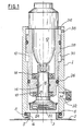
- the device according to the invention comprises a cylindrical envelope 1 which is provided, at one of its ends, with means allowing its sealed application on a barrel 2, around the bung 3 thereof.
- the drain 3 is surrounded by a flange 4, internally threaded and provided with an external bead 5.
- the casing 1 therefore comprises simply a groove 6 in which is housed an O-ring 8 of which the diameter is sufficient for it to be tightly tightened tightly against the bead 5, when the envelope 1 is fitted around the flange 4.
- the casing 1 is also open at its end opposite the groove 6 and contains a piston 10, elongated and hollow, which supports a motor 12 for driving a key 14 for positioning the shutter.
- the key 14 comprises a rod 16 rotatably mounted, by means of ball bearings 18, in the wall of the piston 10 and protruding outside the latter, opposite the groove 6 to carry a head 20 provided with means 22 retainer 24.
- the retaining means 22 are, for example, constituted by a magnet and they retain a closure cap 24 for closing the plug, which is externally threaded and intended to be screwed into the flange 4.
- the hollow piston 10 is mounted with sealed sliding inside the casing 1, thanks to an O-ring 26 in contact with the wall of this casing. It also comprises, in the vicinity of its end opposite to the head 20, a portion 28 of larger diameter which slides in a widened bore 30 of the casing 1 and thus forms a double-acting cylinder for controlling the movement of the piston 10 in casing 1.
- the casing 1 also includes a nozzle 32 for communicating with a source of pressurized fluid, which has not been shown so as not to complicate the drawing.
- a pressure detector 34 is mounted, for example in this nozzle, so as to control the pressure prevailing in this part of the casing 1, between the piston and the barrel.
- the gas, or the vapors, intended to constitute the "trough of the road” is introduced into the barrel 2 by the nozzle 32, which is in communication with the pressure source.
- the head 20 of the key 14 and the capsule 24 being spaced from the plug 3, this gas freely enters the barrel.
- the jack constituted by the piston 28 and the enlarged part 30 of the casing 1, is actuated, fluid under pressure being introduced into the upper chamber 36 of this jack through an orifice 38, and the motor 12 is started.
- the engine 12 can then be stopped and communication with the source of pressurized gas closed.
- the pressure inside the casing 1, between the head 20 and the piston 10 is still significantly less than that of the fluid acting in the chamber 36, so that it does not oppose the movement of this piston under the action of the motor 12, which facilitates the positioning of the capsule.
- the barrel being closed, the closing device, and in particular the casing 1, can easily be removed by moving it away from the collar 3, the elasticity of the seal 8 allowing this movement.
- the device which has just been described also makes it possible to install, on a bung of the barrel, shutters of different types from that which has just been described.
- the head 20 could carry a shutter intended to be fixed by engagement with a bayonet or by another suitable system.
- the closure is carried out in the same way, the key 14 being able to move in rotation and / or axially, as required, after the barrel 2 and the nozzle 32 have been isolated in connection with the source. pressurized fluid.
- the barrel closed by means of such a device has an internal overpressure, so that after the liquid which fills it has cooled, the vacuum due to the contraction of this liquid is compensated by the determined overpressure initially provided for. The risks of implosion of the barrel are then eliminated.
- the pressure of the contents of the barrel at the time of closing of the latter can, moreover, easily be adapted to each filling product by means of a simple adjustment of the shutter release threshold.
- the use of a single type container therefore no longer has any drawbacks.
- the supply of pressurized gas, as well as the actuation of the jack and the starting of the engine 12, can be obtained by any suitable means and even if desired, be triggered manually by an operator informed by the pressure detector. , possibly associated with an alarm.
- an automatic control for example pneumatic, is used, subject to the detector 34 which causes the actuator and the motor 12 to be actuated, either simultaneously as soon as the adjustment pressure is reached in the enclosure 1, or successively, the motor 12 only starting when the capsule 24 is in contact with the bung on the barrel, as well as the stopping of these drives at the end of the closure.
- the motor 12 is preferably a pneumatic motor so that the entire device operates with air or gas and can even be connected to a single source.
- the realization of the device is thus simplified but also its safety, so that it can be used regardless of the nature of the liquid contained in this barrel.
Landscapes
- Engineering & Computer Science (AREA)
- Mechanical Engineering (AREA)
- Chemical & Material Sciences (AREA)
- Dispersion Chemistry (AREA)
- Pressure Vessels And Lids Thereof (AREA)
- Filling Or Discharging Of Gas Storage Vessels (AREA)
Claims (6)
Applications Claiming Priority (2)
| Application Number | Priority Date | Filing Date | Title |
|---|---|---|---|
| FR8512013A FR2586008B1 (fr) | 1985-08-06 | 1985-08-06 | Dispositif de fermeture pour fut metallique |
| FR8512013 | 1985-08-06 |
Publications (2)
| Publication Number | Publication Date |
|---|---|
| EP0213035A1 EP0213035A1 (de) | 1987-03-04 |
| EP0213035B1 true EP0213035B1 (de) | 1988-07-20 |
Family
ID=9322024
Family Applications (1)
| Application Number | Title | Priority Date | Filing Date |
|---|---|---|---|
| EP19860401752 Expired EP0213035B1 (de) | 1985-08-06 | 1986-08-05 | Verschlussvorrichtung für Metallfuss |
Country Status (5)
| Country | Link |
|---|---|
| EP (1) | EP0213035B1 (de) |
| DE (1) | DE3660398D1 (de) |
| ES (1) | ES2001285A6 (de) |
| FR (1) | FR2586008B1 (de) |
| PT (1) | PT83158B (de) |
Families Citing this family (3)
| Publication number | Priority date | Publication date | Assignee | Title |
|---|---|---|---|---|
| DE19500334A1 (de) * | 1995-01-07 | 1996-07-11 | Petra Boehm | Verschlußvorrichtung für Behälter |
| CN102155385A (zh) * | 2011-03-22 | 2011-08-17 | 菏泽市花王高压容器有限公司 | 一种低温绝热液体贮罐抽真空装置 |
| CN102312871A (zh) * | 2011-07-11 | 2012-01-11 | 山西晋西压力容器有限责任公司 | 一种机械式压力转换容器 |
Family Cites Families (2)
| Publication number | Priority date | Publication date | Assignee | Title |
|---|---|---|---|---|
| GB748726A (en) * | 1952-10-31 | 1956-05-09 | California Research Corp | Improvements in or relating to a device for the capping of drums and barrels |
| GB875833A (en) * | 1958-02-28 | 1961-08-23 | British Xylonite Co Ltd | Packaging of deformable containers |
-
1985
- 1985-08-06 FR FR8512013A patent/FR2586008B1/fr not_active Expired
-
1986
- 1986-08-05 DE DE8686401752T patent/DE3660398D1/de not_active Expired
- 1986-08-05 EP EP19860401752 patent/EP0213035B1/de not_active Expired
- 1986-08-06 PT PT8315886A patent/PT83158B/pt not_active IP Right Cessation
- 1986-08-06 ES ES8601528A patent/ES2001285A6/es not_active Expired
Also Published As
| Publication number | Publication date |
|---|---|
| PT83158A (fr) | 1986-09-01 |
| EP0213035A1 (de) | 1987-03-04 |
| ES2001285A6 (es) | 1988-05-01 |
| FR2586008B1 (fr) | 1988-02-26 |
| FR2586008A1 (fr) | 1987-02-13 |
| DE3660398D1 (en) | 1988-08-25 |
| PT83158B (pt) | 1990-08-31 |
Similar Documents
| Publication | Publication Date | Title |
|---|---|---|
| EP1109727B1 (de) | Verschlussvorrichtung für eine sektflasche | |
| EP0342109B1 (de) | Verschlusseinrichtung mit drehbarer Manschette für Flakons und ähnliche Behälter | |
| EP0235065B1 (de) | Behälterabfüllanlage unter Verwendung von Gegendruck | |
| EP0485244B1 (de) | Ausgabeventil für einen Behälter mit einer unter einem Druck eines Gases stehenden Flüssigkeit und mit einem derartigen Ventil versehener Behälter | |
| CH422561A (fr) | Distributeur-doseur | |
| EP0642839A1 (de) | Verfahren und Vorrichtung zum Spenden und Lagern eines, in einem mit Treibgas unter Druck gesetzten Behälter enthaltenen, flüssigen Produktes | |
| FR2509689A1 (fr) | Dispositif et procede pour assurer le transfert de facon aseptique d'un liquide contenu dans un recipient jusqu'a un autre recipient | |
| EP0213035B1 (de) | Verschlussvorrichtung für Metallfuss | |
| LU87748A1 (fr) | Dispositif de neutralisation d'une soupape de pression residuelle d'une bouteille a gaz | |
| EP0375532B1 (de) | 2-Wege-Ventil zum Stromabwärts-Einbau in einer molchfähigen Flüssigkeitsverteilungsleitung | |
| FR2704516A1 (fr) | Procédé de bouchage sous gaz inerte de récipients et dispositif pour sa mise en Óoeuvre. | |
| FR2690419A1 (fr) | Capsule distributrice pour produits liquides ou pâteux. | |
| FR2890940A1 (fr) | Dispositif de remplissage en liquide de recipient aerosol, installation de remplissage apte a recevoir un tel dispositif et recipient aerosol equipe d'un tel dispositif de remplissage | |
| EP0374493A1 (de) | Gasflaschenventil | |
| EP0368724A1 (de) | Spenderaufsatz für Additive zur Montage auf einem Behälter sowie Behälter mit einem solchen Spenderaufsatz | |
| WO1997029028A1 (fr) | Dispositif de distribution d'un produit fluide contenu dans un reservoir ferme hermetiquement | |
| EP0163584A1 (de) | Vorrichtung zur Ölprobennahme aus der Ölwanne eines Verbrennungsmotors und gleichartiger Geräte | |
| FR2541746A1 (fr) | Bouteille en acier pour un appareil a boissons | |
| FR2537092A1 (fr) | Bouchon a verseur pour tous types de bouteille de boisson gazeuse | |
| FR2637651A1 (fr) | Dispositif a utiliser avec un moteur | |
| FR2552401A1 (fr) | Bonde perfectionnee pour futs, conteneurs et recipients analogues | |
| WO2016020621A2 (fr) | Dispositif de traitement d'eau de grande capacité | |
| WO1999017999A1 (fr) | Dispositif pour l'ouverture d'un contenant renfermant un liquide effervescent | |
| FR2693437A1 (fr) | Dispositif pour la distribution d'un liquide et procédé de distribution d'un liquide. | |
| FR2730708A1 (fr) | Distributeur a pompe et poche souple deformable pour produits fluides et procede pour son remplissage et son vidage |
Legal Events
| Date | Code | Title | Description |
|---|---|---|---|
| PUAI | Public reference made under article 153(3) epc to a published international application that has entered the european phase |
Free format text: ORIGINAL CODE: 0009012 |
|
| AK | Designated contracting states |
Kind code of ref document: A1 Designated state(s): BE DE GB NL SE |
|
| 17P | Request for examination filed |
Effective date: 19870327 |
|
| 17Q | First examination report despatched |
Effective date: 19871008 |
|
| GRAA | (expected) grant |
Free format text: ORIGINAL CODE: 0009210 |
|
| AK | Designated contracting states |
Kind code of ref document: B1 Designated state(s): BE DE GB NL SE |
|
| GBT | Gb: translation of ep patent filed (gb section 77(6)(a)/1977) | ||
| REF | Corresponds to: |
Ref document number: 3660398 Country of ref document: DE Date of ref document: 19880825 |
|
| PLBE | No opposition filed within time limit |
Free format text: ORIGINAL CODE: 0009261 |
|
| STAA | Information on the status of an ep patent application or granted ep patent |
Free format text: STATUS: NO OPPOSITION FILED WITHIN TIME LIMIT |
|
| 26N | No opposition filed | ||
| PGFP | Annual fee paid to national office [announced via postgrant information from national office to epo] |
Ref country code: DE Payment date: 19940727 Year of fee payment: 9 |
|
| PGFP | Annual fee paid to national office [announced via postgrant information from national office to epo] |
Ref country code: GB Payment date: 19940729 Year of fee payment: 9 |
|
| PGFP | Annual fee paid to national office [announced via postgrant information from national office to epo] |
Ref country code: SE Payment date: 19940816 Year of fee payment: 9 |
|
| PGFP | Annual fee paid to national office [announced via postgrant information from national office to epo] |
Ref country code: NL Payment date: 19940831 Year of fee payment: 9 |
|
| PGFP | Annual fee paid to national office [announced via postgrant information from national office to epo] |
Ref country code: BE Payment date: 19940909 Year of fee payment: 9 |
|
| EAL | Se: european patent in force in sweden |
Ref document number: 86401752.0 |
|
| PG25 | Lapsed in a contracting state [announced via postgrant information from national office to epo] |
Ref country code: GB Effective date: 19950805 |
|
| PG25 | Lapsed in a contracting state [announced via postgrant information from national office to epo] |
Ref country code: SE Effective date: 19950806 |
|
| PG25 | Lapsed in a contracting state [announced via postgrant information from national office to epo] |
Ref country code: BE Effective date: 19950831 |
|
| BERE | Be: lapsed |
Owner name: VAN LEER (FRANCE) Effective date: 19950831 |
|
| PG25 | Lapsed in a contracting state [announced via postgrant information from national office to epo] |
Ref country code: NL Effective date: 19960301 |
|
| GBPC | Gb: european patent ceased through non-payment of renewal fee |
Effective date: 19950805 |
|
| NLV4 | Nl: lapsed or anulled due to non-payment of the annual fee |
Effective date: 19960301 |
|
| PG25 | Lapsed in a contracting state [announced via postgrant information from national office to epo] |
Ref country code: DE Effective date: 19960501 |
|
| EUG | Se: european patent has lapsed |
Ref document number: 86401752.0 |