EP0212993B1 - Elektrische ferngesteuerte Anlagen - Google Patents
Elektrische ferngesteuerte Anlagen Download PDFInfo
- Publication number
- EP0212993B1 EP0212993B1 EP19860401154 EP86401154A EP0212993B1 EP 0212993 B1 EP0212993 B1 EP 0212993B1 EP 19860401154 EP19860401154 EP 19860401154 EP 86401154 A EP86401154 A EP 86401154A EP 0212993 B1 EP0212993 B1 EP 0212993B1
- Authority
- EP
- European Patent Office
- Prior art keywords
- electronic circuit
- pulse
- appliance
- motor
- state
- Prior art date
- Legal status (The legal status is an assumption and is not a legal conclusion. Google has not performed a legal analysis and makes no representation as to the accuracy of the status listed.)
- Expired - Lifetime
Links
Images

Classifications
-
- H—ELECTRICITY
- H01—ELECTRIC ELEMENTS
- H01H—ELECTRIC SWITCHES; RELAYS; SELECTORS; EMERGENCY PROTECTIVE DEVICES
- H01H47/00—Circuit arrangements not adapted to a particular application of the relay and designed to obtain desired operating characteristics or to provide energising current
- H01H47/22—Circuit arrangements not adapted to a particular application of the relay and designed to obtain desired operating characteristics or to provide energising current for supplying energising current for relay coil
- H01H47/226—Circuit arrangements not adapted to a particular application of the relay and designed to obtain desired operating characteristics or to provide energising current for supplying energising current for relay coil for bistable relays
Definitions
- the present invention relates to an improvement to electrical remote control devices, such as remote control switches, timers, relays, time relays. More specifically, the invention relates to such devices which are associated with control means applying to an input of the device an alternating voltage, preferably from the supply network, for a random period or not, these means being usually consisting of push buttons, joysticks, manual switches, etc.
- These devices typically comprise one or more motor means, for example one or more fixed coils, which are supplied with current, from the AC network, by a control means such as, for example, a push button.
- a control means such as, for example, a push button.
- the flow of current through the coil causes the state to change or the device topple over.
- the duration of change of state is short but the duration of the command which causes it is random since it depends on the person or the body which actuates the control means. Consequently, the dimensions and the characteristics of the motor means are determined so as to allow, without deterioration, a long-term, or even permanent, current demand.
- Devices have already been provided intended, in certain cases, to limit in time the duration of passage of the current in motor means, but the devices proposed, or else are not adapted to devices such as those which the invention is proposes to improve and which must be of a very low cost price, or else do not have sufficient operational reliability and are necessarily sized according to their operating voltage.
- the document FR-A-2 498 807 describes a bistable relay operating as a monostable in order to obtain a monostable relay consuming energy only at the switching time, thus making it possible to limit the consumption of the monostable relays.
- Document FR-A-1 209 706 begins an actuating device requiring the establishment of a circuit comprising a direct current source. However, this device operates in transient and not stable current conditions, which means that such a device is unsuitable for operation on the network.
- the invention proposes to remedy these drawbacks and to provide an improvement to these electrical devices which allows, in order to achieve a very low cost price, to undersize the motor means by limiting their duration of actuation while ensuring the proper functioning of the device whatever the duration and / or the voltage of the control, under conditions at least as good as in the case of conventional electrical remote control devices.
- Another objective of the invention is to provide such an improvement which allows, without exaggerated investments, to have these devices perform more elaborate, more complex and / or additional functions.
- the subject of the invention is an improvement to electrical remote control devices with a bistable mechanism, such as remote switches with a bistable mechanism, comprising wound motor means intended to be traversed by an alternating electric motor current to cause a change of state of the apparatus, with each passage of alternating current, the new state remaining maintained without consumption of driving electrical energy until the passage again, in the wound motor means, of alternating current causing the tilting of the apparatus towards the other state, and of the actuated control means, for a random duration or not, for addressing the electric motor current to the wound motor means, characterized in that the dimensioning of said wound motor means is less than that which would support a continuous passage of the electric motor current or the highest voltage relating to the supply of said motor means, and in that said control means comprise an electronic circuit sensitive to a control member nde and being able to be actuated, from an alternating current source, during the aforementioned duration to deliver, to said wound motor means, a driving pulse of short-lived alternating electric motor current.
- duration is meant, in the sense of the present invention, a duration allowing the passage of a sufficient motive power, coming from the alternating network, in the wound means, to undoubtedly cause the desired change of state.
- This duration is preferably between a few milliseconds or a few tens of milliseconds and a few hundred milliseconds. This also allows said motor means to withstand without damage the overvoltages linked to the different supply voltages.
- the electronic circuit can be arranged, in accordance with the invention, to allow the device to perform usual functions such as timer, relay, time relay, timed remote switches or other more complex functions.
- the electronic circuit is arranged so as to deliver only a single driving pulse when the control member is actuated, even if the actuation of this member lasts longer than said duration of the pulse.
- the two variants can be combined by allowing the electronic circuit to recognize the end of an actuation while establishing, after the end of the electric driving pulse, a refractory period of suitable length, for example calibrated in proportion to the frequency d 'use.
- the electronic circuit can, moreover, be arranged so as to allow the apparatus to perform more complex or additional functions.
- a remote control switch could, in addition to its manual control, be remote-controlled with a hierarchy of control.
- the invention is applicable to bistable devices in which each of the two states remains maintained without consumption of motor current. Switching from one state to another can either be subject, in both directions, to an actuation (or end of actuation) of the control member, for example in the case of a remote control switch or d '' a relay, or be done automatically in one of the two directions, for example, at the end of the operation of a timer.
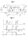
- the remote switch shown is intended to open and close a switch 1 at the terminals P1, P2 of a user circuit. It usually comprises a coil 2 actuating a conventional bistable mechanism 3 with a magnetic armature sensitive to the coil, a spring and means with two stable positions.
- the control means comprise a usual control member such as a push-button switch 4 at the terminals A1, A2 of an actuation circuit of the coil 2 in connection with the alternating current source S.
- an electronic circuit 5 is interposed on the circuit A1, A2 and receives the current, of random duration, coming from a closing of the push-button switch 4.
- This electronic circuit 5, when it is thus actuated by the front amount of the pulse t 1, delivers at the terminals C1, C2 of the coil 2, a driving pulse of alternating current of length t o predetermined.
- a first actuation of the pusher 4, for any duration t1 causes, whatever the length of t1, a pulse t o which switches the remote control switch from state O (open) to l 'state F (closed).
- Another actuating pulse, of any duration t2, occurring later, also causes a driving pulse of duration t o which switches the remote control switch from state F to state O.
- the electronic circuit 5 can thus be produced, very inexpensively, with a conventional thyristor 5a for shaping a pulse t o controlled, through a NAND gate 5b, by the push-button switch 4, and by a monostable time base 5c, itself actuated by the push button and tilted during a period t3, which makes the thyristor insensitive, after each rising edge of pulse t o , for a predetermined period t3.
- a conventional thyristor 5a for shaping a pulse t o controlled, through a NAND gate 5b, by the push-button switch 4, and by a monostable time base 5c, itself actuated by the push button and tilted during a period t3, which makes the thyristor insensitive, after each rising edge of pulse t o , for a predetermined period t3.
- the cross-section of the conductor of the coil 2 is reduced below the value which would be necessary in order to be able to resist a continuous passage of the motor current in the coil.
- These characteristics will depend on the length of the pulse t o and, incidentally, on the duration of the period t3, if the latter is very short. This can reduce the price, weight and size of the device.
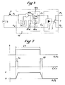
- the contact 1 is actuated by an assembly 6 comprising the coil 2 and a bistable mechanism 3 comprising in particular an auxiliary contact and a return 7.
- the usual timer means 8 of timer is associated with an electronic circuit 9 of so that an actuating pulse of any duration t5 from the pusher 4 causes the sending, at the terminals C1, C2 of the coil, of a short duration driving pulse t o , which causes the closing of the switch 1 and the auxiliary contact, and therefore the switching on of the delay means 8.
- the delay means 8 cause the circuit 9 to generate a new driving pulse t o which causes the opening of contact 1 and therefore the switch from state F to state O.
- a refractory period t3 can also be provided and one can in particular use the time delay means to make the circuit 9 refractory to any request from the push-button switch 4 during the period t6 and / or during a refractory period t3 of a duration adapted to the capacity of the motor means allowing recycling of a new period t'6
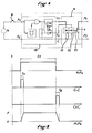
- the relay represented comprises the switch 1, the coil 2 and the mechanism 3 identical to that of FIG. 1.
- An electronic circuit 10 is interposed between the push-button switch 4 (or an external control contact) and the terminals C1, C2 of the coil.
- This circuit comprises a control assembly 10a actuated, through a NAND gate, in the same way as in the case of FIG. 1.
- This assembly 10a comprises, in known manner, two thyristors 10b, 10c and a capacitor 10d , one of the thyristors 10b generating the first pulse t o at the closing of the member 4 and the other 10c the second pulse t8 at the end of the actuation time t7, this second pulse t8 being this time generated by the capacity 10d.
- the rising edge of the pulse t7 causes the circuit 10 to generate a driving pulse t o which causes the switching from state O to state F.
- the falling edge of pulse t7 causes a new driving pulse t8 to be sent which switches the relay back in the opposite direction.
- the relay shown comprises, in addition to the contact 1, two coils 11 and 12, each similar to the coil 2 and acting one for opening the contact 1 and the other for closing it.
- a usual mechanism 13 connects the contact 1 to the movable armatures of the two coils.
- a circuit electronics 14 is interposed between circuit A1, A2 and terminals C and C1, C and C2 of the respective coils 11 and 12.
- the actuating pulse t7 causes, by its rising edge, the sending by the circuit 14, of a pulse t o at the terminals C1 and C of the coil 11 and, consequently, the switching from state O to the state F.
- the falling edge of the pulse t l'iki causes the sending, on the terminals C2 and C of the coil 12, of another pulse t8 which switches the relay from state F to state O.
- Means can also be provided to make the circuit refractory for a determined period.
- the device according to the invention can be produced in the form of a usual remote control device by incorporating into the usual modular box of the device, or a similar box, the electronic circuit sensitive to the control member.
- this circuit can be incorporated in an independent modular box which is connected on the one hand to the control member and on the other hand to a conventional remote control device, the device according to the invention then being composed of all of these two elements connected together.
Landscapes
- Relay Circuits (AREA)
- Selective Calling Equipment (AREA)
Claims (11)
- Elektrische ferngesteuerte Anlage mit bistabilen Mechanismus, wie z.B. Fernschalter, der gewickelte Antriebsmittel enthält, welche dazu bestimmt sind, von einem Antriebswechselstrom durchströmt zu werden, um bei jeder Durchströmung eine Schaltzustandsänderung der Anlage herbeizuführen, der neue Schaltzustand bleibt ohne Verbrauch von elektrischer Antriebsenergie erhalten, bis eine erneute Durchströmung der gewickelten Antriebsmittel durch Wechselstrom das Umkippen der Anlage zum anderen Schaltzustand verursacht und mit Steuerungsmittel, die für eine bestimmte oder unbestimmte Dauer betätigt werden, um den Wechselstrom zu den gewickelten Antriebsmitteln zu leiten,
dadurch gekennzeichnet,
daß die Dimensionierung der gewickelten Antriebsmittel (2, 11, 12) geringer ist als diejenige, die eine ständige Durchströmung durch den elektrischen Antriebsstrom oder die bezüglich der Einspeisung der Antriebsmittel höchste Spannung ertragen würde, und daß die Steuerungsmittel (A1, A2, C1, C2) einen elektrischen Schaltkreis (5, 9, 10, 14) enthalten, der auf ein Steuerungsorgan (4) anspricht und der von einer Wechselstromquelle aus betätigt werden kann, um während der Betätigungsdauer den gewickelten Antriebsmitteln einen elektrischem Antriebswechselstromimpuls kurzer Dauer zuzuleiten. - Anlage nach Anspruch 1, dadurch gekennzeichnet, daß die Dauer des Antriebsimpulses zwischen einigen Millisekunden und einigen Hundert Millisekunden liegt.
- Anlage nach einem der Ansprüche 1 oder 2, dadurch gekennzeichnet, daß der elektronische Schaltkreis die Unterbrechung der Betätigung des Steuerungsorgans (4) erfaßt, um wieder für das Steuerungsorgan ansprechbar zu werden.
- Anlage nach einem der Ansprüche 1 bis 3, dadurch gekennzeichnet, daß der elektronische Schaltkreis nach einem Antriebsimpuls für eine im voraus festgelegte Abweisungsdauer für das Steuerungsorgan unansprechbar ist.
- Anlage nach einem der Ansprüche 1 bis 4, dadurch gekennzeichnet, daß der elektronische Schaltkreis (5, 9, 10, 14) in einem Gehäuse der ferngesteuerten Anlage eingebaut ist.
- Anlage nach einem der Ansprüche 1 bis 5, dadurch gekennzeichnet, daß der elektronische Schaltkreis (5, 9, 10, 14) in einem Gehäuse einer ferngesteuerten, auf diesen Schaltkreis geschalteten Anlage getrennten Gehäuse eingebaut ist.
- Fernschalter nach einem der Ansprüche 1 bis 6, dadurch gekennzeichnet, daß der elektronische Schaltkreis (5) auf die ansteigende Wellenstirn des aus dem Steuerungsorgan (4) kommenden Steuerungsimpulses anspricht, um die aufeinanderfolgenden Zustandsveränderungen zu verursachen.
- Anlage nach einem der Ansprüche 1 bis 7, dadurch gekennzeichnet, daß der elektronische Schaltkreis Mittel enthält, die der Anlage gestatten, zusätzliche Funktionen zu gewährleisten, wie Schaltuhren, Relais, Verzögerungsrelais, ferngesteuerter Zeitschalter.
- Anlage nach Anspruch 8, Bestandsteil einer Schaltuhr, bei der der elektronische Schaltkreis (9) mit dem Zeitschaltmittel (8) der Schaltuhr verbunden ist, hierbei spricht der elektronische Schaltkreis auf die ansteigende Wellenstirn eines aus dem Steuerungsorgan (4) kommenden Steuerungsimpulses und auch auf das Zeitschaltmittel an, um am Ende der Zeitschaltung einen Antriebsimpuls zu senden.
- Anlage nach Anspruch 9, dadurch gekennzeichnet, daß die Zeitschaltuhr nach einer Leistungsfähigkeit der Antriebsmittel angemessenen Abweisungszeit (t ₃) erneut eingestellt werden kann.
- Anlage nach Anspruch 8, Bestandteil eines Relais, bei dem der elektronische Schaltkreis (1o) einerseits auf die ansteigende Wellenstirn eines aus dem Steuerungsorgan (4) kommenden Steuerungsimpulses anspricht, um eine erste Zustandsveränderung zu verursachen, und andererseits auf die absteigende Wellenstirn des Impulses, um eine zweite Zustandsveränderung zu verursachen.
Applications Claiming Priority (2)
| Application Number | Priority Date | Filing Date | Title |
|---|---|---|---|
| FR8508779 | 1985-06-11 | ||
| FR8508779A FR2583192B1 (fr) | 1985-06-11 | 1985-06-11 | Perfectionnement aux appareils de telecommande electriques |
Publications (2)
| Publication Number | Publication Date |
|---|---|
| EP0212993A1 EP0212993A1 (de) | 1987-03-04 |
| EP0212993B1 true EP0212993B1 (de) | 1993-03-17 |
Family
ID=9320079
Family Applications (1)
| Application Number | Title | Priority Date | Filing Date |
|---|---|---|---|
| EP19860401154 Expired - Lifetime EP0212993B1 (de) | 1985-06-11 | 1986-05-30 | Elektrische ferngesteuerte Anlagen |
Country Status (3)
| Country | Link |
|---|---|
| EP (1) | EP0212993B1 (de) |
| DE (1) | DE3688027T2 (de) |
| FR (1) | FR2583192B1 (de) |
Families Citing this family (3)
| Publication number | Priority date | Publication date | Assignee | Title |
|---|---|---|---|---|
| FR2615012B1 (fr) * | 1987-05-06 | 1989-11-24 | Hager Electro | Circuit de commande pour appareils de telecommande electriques, notamment telerupteurs, et appareils incorporant ce circuit |
| DE3726624A1 (de) * | 1987-08-11 | 1989-03-02 | Kloeckner Moeller Elektrizit | Schutzeinrichtung fuer den elektromagnetischen antrieb eines schaltgeraetes |
| CN111624901B (zh) * | 2019-02-28 | 2024-03-01 | 施耐德电器工业公司 | 控制方法、控制装置 |
Family Cites Families (4)
| Publication number | Priority date | Publication date | Assignee | Title |
|---|---|---|---|---|
| FR1209706A (fr) * | 1958-08-30 | 1960-03-03 | Dispositif de commande électromagnétique | |
| FR1387982A (fr) * | 1963-12-23 | 1965-02-05 | Saxby | Relais universel à éléments standards interchangeables |
| US4433357A (en) * | 1980-10-13 | 1984-02-21 | Matsushita Electric Works Ltd. | Drive circuit for a latching relay |
| FR2498807A1 (fr) * | 1981-01-23 | 1982-07-30 | Socapex | Relais monostable a faible consommation |
-
1985
- 1985-06-11 FR FR8508779A patent/FR2583192B1/fr not_active Expired
-
1986
- 1986-05-30 EP EP19860401154 patent/EP0212993B1/de not_active Expired - Lifetime
- 1986-05-30 DE DE19863688027 patent/DE3688027T2/de not_active Expired - Fee Related
Also Published As
| Publication number | Publication date |
|---|---|
| DE3688027D1 (de) | 1993-04-22 |
| FR2583192B1 (fr) | 1987-08-07 |
| FR2583192A1 (fr) | 1986-12-12 |
| EP0212993A1 (de) | 1987-03-04 |
| DE3688027T2 (de) | 1993-10-14 |
Similar Documents
| Publication | Publication Date | Title |
|---|---|---|
| CA1239692A (fr) | Dispositif de commutation a composition variable | |
| EP0108678B1 (de) | Ferngesteuertes Stromschaltgerät | |
| FR2584529A1 (fr) | Disjoncteur-contacteur electrique, notamment pour des batteries de condensateurs | |
| FR2591246A1 (fr) | Fer a repasser electrique muni d'un dispositif automatique de securite | |
| FR2707794A1 (fr) | Appareil interrupteur de protection. | |
| EP0199612B1 (de) | Mehrpoliges Schaltgerät mit Fernsteuerung | |
| EP0212993B1 (de) | Elektrische ferngesteuerte Anlagen | |
| FR2536904A1 (fr) | Circuit electronique de commande d'un appareillage a fonctionnement multiple equipe d'un mecanisme a electro-aimant | |
| FR2618270A1 (fr) | Circuit et appareillage pour l'alimentation protegee d'une charge a l'aide d'interrupteurs statiques et electromecaniques. | |
| EP0079820B1 (de) | Schaltgerät mit Anordnungen zur Selbstunterbrechung und mit einem örtlichen Antriebsteil | |
| EP0475247A1 (de) | Betätigungsvorrichtung für Schalter | |
| FR2653593A1 (fr) | Telerupteur a dispositif de limitation de courant ref. 1736. | |
| EP0834975B1 (de) | Elektrisches Verteilungsanschlusselement mit hybridem Begrenzerblock | |
| EP0424283B1 (de) | Steuervorrichtung für einen ferngesteuerten Schalter | |
| EP0018867A2 (de) | Geschützte thyristorbestückte Stromzufuhr | |
| EP0854491A1 (de) | Schaltschutz | |
| EP0218491B1 (de) | Hilfsanordnung für das elektrische Schalten, insbesondere für relais mit Kontakten, Schürze oder gleichartige fernbetätigte Anordnungen | |
| EP0290314B1 (de) | Ansteuerschaltung für elektrische Fernbedienungsapparate, besonders Fernauslöser und Apparate, die diese Schaltung enthalten | |
| FR2498807A1 (fr) | Relais monostable a faible consommation | |
| EP0362085B1 (de) | Schaltgerät mit Fernsteuerung | |
| EP0352391A1 (de) | Steuervorrichtung zum Ein- und Ausschalten einer elektrischen Leistungsschaltung | |
| EP0078534B1 (de) | Einrichtung zur Steuerung des Ab- und Einschaltzyklus eines Trennschalters | |
| CH520449A (fr) | Déclencheur électronique | |
| FR2735613A1 (fr) | Perfectionnement aux contacteurs electriques | |
| CH322710A (fr) | Pièce d'horlogerie électrique |
Legal Events
| Date | Code | Title | Description |
|---|---|---|---|
| PUAI | Public reference made under article 153(3) epc to a published international application that has entered the european phase |
Free format text: ORIGINAL CODE: 0009012 |
|
| AK | Designated contracting states |
Kind code of ref document: A1 Designated state(s): BE CH DE FR GB IT LI |
|
| 17P | Request for examination filed |
Effective date: 19870908 |
|
| 17Q | First examination report despatched |
Effective date: 19901129 |
|
| GRAA | (expected) grant |
Free format text: ORIGINAL CODE: 0009210 |
|
| AK | Designated contracting states |
Kind code of ref document: B1 Designated state(s): BE CH DE FR GB IT LI |
|
| PG25 | Lapsed in a contracting state [announced via postgrant information from national office to epo] |
Ref country code: IT Free format text: LAPSE BECAUSE OF FAILURE TO SUBMIT A TRANSLATION OF THE DESCRIPTION OR TO PAY THE FEE WITHIN THE PRE;WARNING: LAPSES OF ITALIAN PATENTS WITH EFFECTIVE DATE BEFORE 2007 MAY HAVE OCCURRED AT ANY TIME BEFORE 2007. THE CORRECT EFFECTIVE DATE MAY BE DIFFERENT FROM THE ONE RECORDED.SCRIBED TIME-LIMIT Effective date: 19930317 |
|
| REF | Corresponds to: |
Ref document number: 3688027 Country of ref document: DE Date of ref document: 19930422 |
|
| PG25 | Lapsed in a contracting state [announced via postgrant information from national office to epo] |
Ref country code: LI Effective date: 19930531 Ref country code: CH Effective date: 19930531 |
|
| GBT | Gb: translation of ep patent filed (gb section 77(6)(a)/1977) |
Effective date: 19930518 |
|
| PLBE | No opposition filed within time limit |
Free format text: ORIGINAL CODE: 0009261 |
|
| STAA | Information on the status of an ep patent application or granted ep patent |
Free format text: STATUS: NO OPPOSITION FILED WITHIN TIME LIMIT |
|
| REG | Reference to a national code |
Ref country code: CH Ref legal event code: PL |
|
| 26N | No opposition filed | ||
| PGFP | Annual fee paid to national office [announced via postgrant information from national office to epo] |
Ref country code: DE Payment date: 19960423 Year of fee payment: 11 |
|
| PGFP | Annual fee paid to national office [announced via postgrant information from national office to epo] |
Ref country code: FR Payment date: 19960524 Year of fee payment: 11 Ref country code: GB Payment date: 19960524 Year of fee payment: 11 |
|
| PGFP | Annual fee paid to national office [announced via postgrant information from national office to epo] |
Ref country code: BE Payment date: 19960612 Year of fee payment: 11 |
|
| PG25 | Lapsed in a contracting state [announced via postgrant information from national office to epo] |
Ref country code: GB Effective date: 19970530 |
|
| PG25 | Lapsed in a contracting state [announced via postgrant information from national office to epo] |
Ref country code: BE Effective date: 19970531 |
|
| BERE | Be: lapsed |
Owner name: S.A. HAGER ELECTRO Effective date: 19970531 |
|
| GBPC | Gb: european patent ceased through non-payment of renewal fee |
Effective date: 19970530 |
|
| PG25 | Lapsed in a contracting state [announced via postgrant information from national office to epo] |
Ref country code: FR Free format text: LAPSE BECAUSE OF NON-PAYMENT OF DUE FEES Effective date: 19980130 |
|
| PG25 | Lapsed in a contracting state [announced via postgrant information from national office to epo] |
Ref country code: DE Free format text: LAPSE BECAUSE OF NON-PAYMENT OF DUE FEES Effective date: 19980203 |
|
| REG | Reference to a national code |
Ref country code: FR Ref legal event code: ST |