EP0212975B1 - Filtervorrichtung - Google Patents
Filtervorrichtung Download PDFInfo
- Publication number
- EP0212975B1 EP0212975B1 EP86306438A EP86306438A EP0212975B1 EP 0212975 B1 EP0212975 B1 EP 0212975B1 EP 86306438 A EP86306438 A EP 86306438A EP 86306438 A EP86306438 A EP 86306438A EP 0212975 B1 EP0212975 B1 EP 0212975B1
- Authority
- EP
- European Patent Office
- Prior art keywords
- riser pipe
- filtering device
- receptacle
- injecting member
- air injecting
- Prior art date
- Legal status (The legal status is an assumption and is not a legal conclusion. Google has not performed a legal analysis and makes no representation as to the accuracy of the status listed.)
- Expired
Links
- 238000001914 filtration Methods 0.000 title claims description 36
- XLYOFNOQVPJJNP-UHFFFAOYSA-N water Substances O XLYOFNOQVPJJNP-UHFFFAOYSA-N 0.000 claims description 28
- 241000252254 Catostomidae Species 0.000 claims description 9
- 239000013013 elastic material Substances 0.000 claims description 4
- 241000251468 Actinopterygii Species 0.000 description 8
- 230000000630 rising effect Effects 0.000 description 5
- 241000195649 Chlorella <Chlorellales> Species 0.000 description 2
- 230000000149 penetrating effect Effects 0.000 description 2
- 229920003002 synthetic resin Polymers 0.000 description 2
- 239000000057 synthetic resin Substances 0.000 description 2
- 241000252229 Carassius auratus Species 0.000 description 1
- 239000000853 adhesive Substances 0.000 description 1
- 230000001070 adhesive effect Effects 0.000 description 1
- 230000000694 effects Effects 0.000 description 1
- 210000003608 fece Anatomy 0.000 description 1
- 238000002347 injection Methods 0.000 description 1
- 239000007924 injection Substances 0.000 description 1
- 239000000463 material Substances 0.000 description 1
- 239000000126 substance Substances 0.000 description 1
Images


Classifications
-
- A—HUMAN NECESSITIES
- A01—AGRICULTURE; FORESTRY; ANIMAL HUSBANDRY; HUNTING; TRAPPING; FISHING
- A01K—ANIMAL HUSBANDRY; AVICULTURE; APICULTURE; PISCICULTURE; FISHING; REARING OR BREEDING ANIMALS, NOT OTHERWISE PROVIDED FOR; NEW BREEDS OF ANIMALS
- A01K63/00—Receptacles for live fish, e.g. aquaria; Terraria
- A01K63/04—Arrangements for treating water specially adapted to receptacles for live fish
- A01K63/045—Filters for aquaria
-
- B—PERFORMING OPERATIONS; TRANSPORTING
- B01—PHYSICAL OR CHEMICAL PROCESSES OR APPARATUS IN GENERAL
- B01D—SEPARATION
- B01D35/00—Filtering devices having features not specifically covered by groups B01D24/00 - B01D33/00, or for applications not specifically covered by groups B01D24/00 - B01D33/00; Auxiliary devices for filtration; Filter housing constructions
- B01D35/26—Filters with built-in pumps filters provided with a pump mounted in or on the casing
Definitions
- the present invention relates to a filtering device comprising a riser pipe basically of cylindrical shape through which in use water in a receptacle into which the filtering device is placed, is circulated.
- the invention is concerned with a filtering device comprising a riser pipe having an outlet port at one end and a porous air injecting member contained within the riser pipe at its other end portion, the air injection member being arranged for connection to a pressurized air source to develop a flow of water within the riser pipe.
- the riser pipe is commonly placed within a receptacle intended for use as an aquarium, at a distance spaced from an inner surface of the receptacle.
- the existence of a space between the riser pipe and the inner surface of the receptacle may permit fish in the aquarium to enter that space and become trapped between the filter and the inner surface.
- a filtering device comprising a riser pipe of basically cylindrical shape having an outlet at one end and being arranged to be placed within a box-like receptacle, and a porous air injecting member contained within the riser pipe at its other end portion, the air injecting member being arranged for connection to a pressurized air source to develop a flow of water within the riser pipe, characterised in that the riser pipe is formed of an elastic material to have a back wall comprising a pair of mounting portions forming an angle slightly greater than 90° and connected to a connecting portion, and a front wall, the back wall being disposed to face into the corner with the front wall facing inwardly of the receptacle when the filtering device is fitted to the receptacle in an upright position with the outlet above the air injecting member, the riser pipe having a cross-sectional configuration such that the back and front walls are connected to form a closed section and there being suckers securely mounted on the outer surfaces of the mounting portions and adapted to attach to
- both the mounting portions tend to move away from the two side surfaces of the receptacle, whereby the suckers are under greater suction, thus ensuring that the riser pipe is reliably secured to the receptacle.
- FIG. 1 illustrating one embodiment of the present invention, there is shown a tank 1 of box-like configuration to form an aquarium for fish such as goldfish, tropical fish and saltwater fish.
- a riser pipe 3 of a filtering device of the present invention is attached to a corner 2 formed by two side wall surfaces 1 a and 1b, intersecting at a right angle, of the tank 1.
- Pressurized air is supplied from an air pump P as a pressurized air source placed outside the tank 1 into the riser pipe 3, thereby producing a rising flow of water in the riser pipe 3, so that water drawn into the riser pipe 3 from the water tank 1 is filtered and then returned into the tank 1.
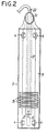
- the filtering device comprises the riser pipe 3, a plurality of suckers 4, filtering elements 5 and a porous air injecting member 6.
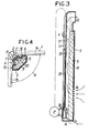
- the riser pipe 3 is basically formed of an elastic material such as a synthetic resin into a cylinder closed at its lower end and having such a cross-sectional configuration that a back wall 7 disposed to be faced to the corner 2 and a front wall 8 disposed to be faced inwardly of the water tank 1 in the attached state are interconnected to form a closed section.
- the back wall 7 is constituted by a pair of mounting portions 9 and 10 connected by a connecting portion 11.
- the mounting portions 9 and 10 are disposed at an angle slightly larger than the 90° angle formed by the side surfaces 1a and 1b of the water tank 1, and the connecting portion 11 is shaped into a circular arc curved to be concave towards the corner 2.
- the front wall 8 is shaped into a trapezoid converging inwardly of the water tank 1.
- An outlet port 12 is provided in the upper end of the riser pipe 3 and opening inwardly of the water tank 1, and an auxiliary water suction port 14 is formed in the lower end wall 13 of the riser pipe 3.
- a plurality of slit-like water suction ports 15 are formed at vertically spaced positions in the lower portion of the front wall 8 of the riser pipe 3.
- a pair of recesses 16 are provided at positions spaced lengthwise of the pipe 3 in both mounting portions 9 and 10, and a housing groove 17 is provided in the connecting portion 11.
- the housing groove 17 is disposed to extend vertically from the upper end to the proximity of the lower end of the riser pipe 3 and has an upper end opening upwardly and a lower end defined by an upwardly facing end wall 18.
- a hole 19 is formed in the end wall 18 to lead to the inside of the riser pipe 3.
- the suckers 4 are securely mounted in the individual recesses 16 in the both mounting portions 9 and 10, respectively, with the base portions of the suckers 4 being engaged with the mounting portions 9 and 10 and moreover, with the front end of each sucker 4 projecting outwardly from the outer surfaces of the mounting portions 9 and 10.
- the filtering elements 5 are each shaped into a column having a cross-sectional configuration substantially corresponding to the cross-sectional configuration of the front wall 8 and are arranged within the riser pipe 3 in a manner to be offset towards the front wall 8.
- a conduit 20 is thus defined between the back wall 7 and the filtering elements 5 within the riser pipe 3 over the entire length of the riser pipe 3, with the upper end thereof connected to the outlet port 12 and the lower end thereof connected to the auxiliary suction port 14.
- the porous air injecting member 6 is formed of a gas-permeable material such as an expandable synthetic resin and is disposed in the lower portion of the conduit 20 so that a smaller diameter connecting pipe 21 integral with the porous air injecting member 6 may project from the hole 19 into the housing groove 17.
- a hose 22 is connected at one end to the air pump P outside the tank 1.
- the hose 22 is introduced through the upper end of the riser pipe 3 into the housing groove 17 to extend downwardly within the housing groove and is connected to the connecting pipe 21 of the porous air injecting member 6.
- the provision of the auxiliary suction port 14 permits the rate of the water penetrating the filtering elements 5 to be controlled at a rate suitable to accelerate the propagation of chlorella and aerobic microbes, so that organic substances such as leftover food and excreta from the fish can be decomposed by the aerobic microbes to prevent any clogging of the filtering elements 5. Furthermore the chlorella provides fresh food for the fish.
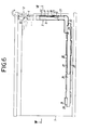
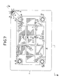
- Figs. 5 to 7 illustrate another embodiment of the present invention, wherein the parts corresponding to those in the previously described embodiment are designated by the same reference numerals.
- Gravel 23 is spread within the tank 1 over the bottom thereof to provide a lower filtering device which utilizes the gravel 23 as a filtering medium to filter water.
- the lower type filtering device comprises a casing 24 placed on the bottom of the tank 1 with at least a part (the whole in this embodiment) buried in the gravel 23, a riser pipe 3' extending upwardly from the casing 24 and being open at its upper portion, and a porous air injecting member 6 being disposed within the riser pipe 3' at its lower end.
- the casing 24 is shaped into a flat rectangular box and has a number of slit-like water suction ports 27 perforated respectively in the upper and lower opposite surfaces thereof.
- Each of the suction ports 27 is provided between adjacent ones of a plurality of parallel protrusions 28, whereby each suction port 27 may be prevented from being clogged with the gravel 23.
- a short cylinder-like connecting pipe portion 29 is integrally mounted on the upper surface of the casing 24 to project therefrom at each of the four corners of the casing 24.
- a communication pipe 30 is also fitted being connected to one of the four connecting pipe portions 29.
- the remaining connecting pipe portions 29 are each plugged with a cap 31.
- the riser pipe 3' has configuration corresponding to that of the riser pipe 3 of the previous embodiment being opened at its lower end, and is permitted to communicate with the inside of the casing 24 by a second communication pipe 33 fitted and connected to the lower portion of the riser pipe 3' and the first communication pipe 30. No filtering element is contained in the riser pipe 3'.
- the casing 24 connected with the riser pipe 3' is placed in the bottom of the tank 1, and with the back wall 7 facing the corner 2, the riser pipe 3' is pressed into the corner 2. This enables the riser pipe 3' to be securely mounted in the corner 2 in close contact with the side surface 1 a and 1 basin the previous embodiment.
- pressurized air is supplied from the air pump P into the porous air injecting member 6, so that air bubbles produced in the porous air injecting member 6 rise within the riser pipe 3' to produce a rising flow of water toward the riser pipe 3' is produced also in the casing 24 communicating with the rising pipe 3', so that water within the tank 1 is passed through the gravel 23 and filtered. Then, the filtered water enters the casing 24 through the suction port 27 and rises within the riser pipe 3' to flow back into the tank 1.
- the inside of the casing 24 has been a mere space in the above embodiment, but it should be understood that the casing 24 may be filled with a filtering medium.
Landscapes
- Life Sciences & Earth Sciences (AREA)
- Environmental Sciences (AREA)
- Marine Sciences & Fisheries (AREA)
- Animal Husbandry (AREA)
- Biodiversity & Conservation Biology (AREA)
- Chemical & Material Sciences (AREA)
- Chemical Kinetics & Catalysis (AREA)
- Farming Of Fish And Shellfish (AREA)
- Filtration Of Liquid (AREA)
Claims (6)
dadurch gekennzeichnet, daß das Steigleitungsrohr (3, 3') aus einem elastischen Material gebildet ist und eine Rückwand (7) mit einem Paar Montageabschnitten (9, 10), die einen Winkel von etwas mehr als 90° bilden, und eine Vorderwand (8) aufweist, wobei die Rückwand (7) so angeordnet ist, daß sie in die Ecke weist, und die Vorderwand (8) zur Innenseite des Behälters (1) weist, wenn die Filtervorrichtung an dem Behälter (1) in aufrechter Stellung mit dem Auslaß (12) oberhalb des Lufteinblasteiles (6) angebracht ist, wobei das Steigleitungsrohr (3,3') eine derartige Querschnittsgestalt aufweist, daß die Vorder- und Rückwand (7, 8) zum Bilden eines geschlossenen Bereichs verbunden sind, und Saugnäpfe (4) an den Außenflächen der Montageabschnitte (9, 10) fest angebracht sind und dafür vorgesehen sind, an den jeweiligen die Ecke bildenden Flächen des Behälters (1) zu haften, um das Steigleitungsrohr (3, 3') in engem Kontakt mit dem Behälter zu halten.
Applications Claiming Priority (4)
| Application Number | Priority Date | Filing Date | Title |
|---|---|---|---|
| JP182805/85 | 1985-08-20 | ||
| JP60182805A JPS6242710A (ja) | 1985-08-20 | 1985-08-20 | 濾過装置 |
| JP198766/85 | 1985-09-09 | ||
| JP60198766A JPS6257621A (ja) | 1985-09-09 | 1985-09-09 | 底面式濾過装置 |
Publications (3)
| Publication Number | Publication Date |
|---|---|
| EP0212975A2 EP0212975A2 (de) | 1987-03-04 |
| EP0212975A3 EP0212975A3 (en) | 1987-09-23 |
| EP0212975B1 true EP0212975B1 (de) | 1991-01-23 |
Family
ID=26501466
Family Applications (1)
| Application Number | Title | Priority Date | Filing Date |
|---|---|---|---|
| EP86306438A Expired EP0212975B1 (de) | 1985-08-20 | 1986-08-20 | Filtervorrichtung |
Country Status (3)
| Country | Link |
|---|---|
| US (1) | US5092991A (de) |
| EP (1) | EP0212975B1 (de) |
| DE (1) | DE3677094D1 (de) |
Cited By (1)
| Publication number | Priority date | Publication date | Assignee | Title |
|---|---|---|---|---|
| CN104663561A (zh) * | 2015-02-28 | 2015-06-03 | 苏州圣艺文体用品有限公司 | 一种自清洁鱼缸 |
Families Citing this family (14)
| Publication number | Priority date | Publication date | Assignee | Title |
|---|---|---|---|---|
| JPS63151321A (ja) * | 1986-12-15 | 1988-06-23 | Suisaku Kk | 濾過装置 |
| JPS63310613A (ja) * | 1987-06-11 | 1988-12-19 | Suisaku Kk | 濾過装置 |
| US5245945A (en) * | 1993-03-01 | 1993-09-21 | Liao Chung Han | Aquarium assembly having partition forming aeration/filter chamber |
| EP0860721B1 (de) * | 1993-03-31 | 2002-06-26 | Sumitomo Electric Industries, Ltd. | Optisches Faserarray und Methode zu seiner Herstellung |
| US5336401A (en) * | 1993-05-14 | 1994-08-09 | Tu Chih Yao | Water filtration and aeration system for aquariums |
| USD392717S (en) | 1997-07-30 | 1998-03-24 | Kencar, Inc. | Aquarium filter |
| US6840192B1 (en) * | 2003-01-17 | 2005-01-11 | Charles M. Pagano | Air supply organizer for aquariums |
| USD537213S1 (en) * | 2004-10-06 | 2007-02-20 | Selstad Scott T | Slotted ventilated post for a rear corner of a terrarium |
| USD537214S1 (en) * | 2004-10-06 | 2007-02-20 | Selstad Scott T | Slotted ventilated post for a front corner of a terrarium |
| US8702981B2 (en) * | 2011-10-18 | 2014-04-22 | Central Garden & Pet Company | Wedge-shaped and stackable filter cartridges |
| CN103053447A (zh) * | 2011-10-20 | 2013-04-24 | 中国水产科学研究院渔业机械仪器研究所 | 一种利用曝气组件的净水养殖系统 |
| CN102966176A (zh) * | 2012-11-23 | 2013-03-13 | 苏州优德通力电气有限公司 | 一种底盘 |
| CN103478055A (zh) * | 2013-10-18 | 2014-01-01 | 海南省水产研究所 | 一种南美白对虾室内工厂化培育装置 |
| US11412718B2 (en) | 2019-04-24 | 2022-08-16 | Erik Ossimina | Fish tank air hose channel apparatus |
Family Cites Families (17)
| Publication number | Priority date | Publication date | Assignee | Title |
|---|---|---|---|---|
| US3119774A (en) * | 1960-06-27 | 1964-01-28 | Aquariums Inc | Undergravel filter |
| US3294239A (en) * | 1963-03-15 | 1966-12-27 | Dayes Frank | Aquarium aerator |
| DE1611095B2 (de) * | 1967-12-05 | 1974-02-21 | Roland 4630 Bochum Hagemann | Aquariums-Filter |
| US3516544A (en) * | 1968-10-25 | 1970-06-23 | Sternco Ind Inc | Underwater aquarium filter |
| US3529574A (en) * | 1968-12-31 | 1970-09-22 | Aquarium Syst Inc | Corner air lift for aquariums |
| US3630367A (en) * | 1969-06-11 | 1971-12-28 | Aquariums Inc | Bottom aquarium filter |
| US3850806A (en) * | 1971-03-23 | 1974-11-26 | H Cohen | Filter and water recirculation system |
| US3717253A (en) * | 1971-12-22 | 1973-02-20 | Sternco Ind Inc | Adjustable bracket and filter for various sizes of home aquariums |
| US3770128A (en) * | 1972-02-23 | 1973-11-06 | M Kast | Device for treating aquarium water |
| US3785494A (en) * | 1973-03-30 | 1974-01-15 | N Sama | Filtering device |
| US3867292A (en) * | 1973-04-10 | 1975-02-18 | Whitsell Darrel Michael | Aquarium filter system |
| US3927643A (en) * | 1974-07-31 | 1975-12-23 | Gerald R Ritzow | Aquarium |
| US4186093A (en) * | 1977-12-19 | 1980-01-29 | Willinger Bros., Inc. | Bottom aquarium filter |
| DE3136243C2 (de) * | 1981-09-12 | 1983-12-08 | Gunther Eheim Fabrik Elektromechanischer Erzeugnisse, 7301 Deizisau | Innenfilter für Aquarien |
| JPS60153910A (ja) * | 1984-01-24 | 1985-08-13 | Mizusaku Kk | 濾過装置 |
| JPS60172323A (ja) * | 1984-02-20 | 1985-09-05 | Mizusaku Kk | 濾過装置 |
| US4620924A (en) * | 1984-10-19 | 1986-11-04 | Penn Plax Plastics, Inc. | Aquarium corner filter |
-
1986
- 1986-08-20 DE DE8686306438T patent/DE3677094D1/de not_active Expired - Lifetime
- 1986-08-20 EP EP86306438A patent/EP0212975B1/de not_active Expired
-
1991
- 1991-05-24 US US07/707,223 patent/US5092991A/en not_active Expired - Lifetime
Cited By (2)
| Publication number | Priority date | Publication date | Assignee | Title |
|---|---|---|---|---|
| CN104663561A (zh) * | 2015-02-28 | 2015-06-03 | 苏州圣艺文体用品有限公司 | 一种自清洁鱼缸 |
| CN104663561B (zh) * | 2015-02-28 | 2018-07-13 | 刘艳娇 | 一种自清洁鱼缸 |
Also Published As
| Publication number | Publication date |
|---|---|
| EP0212975A2 (de) | 1987-03-04 |
| EP0212975A3 (en) | 1987-09-23 |
| DE3677094D1 (de) | 1991-02-28 |
| US5092991A (en) | 1992-03-03 |
Similar Documents
| Publication | Publication Date | Title |
|---|---|---|
| US5092991A (en) | Filtering device | |
| USD260175S (en) | Fluid filter unit | |
| MX170208B (es) | Cabeza limpiadora de succion | |
| EP0131934A3 (en) | An assay cartridge | |
| JPS60172323A (ja) | 濾過装置 | |
| EP0341356B1 (de) | Anordnung zum Filtrieren | |
| US5316670A (en) | Filtering device for aquariums | |
| USD332368S (en) | Fluid dispenser | |
| USD325255S (en) | Fluid delivery pump for intravenous solutions | |
| USD273511S (en) | Two fluid press-feeding pump | |
| JPH0222687B2 (de) | ||
| JPH0222686B2 (de) | ||
| JP3311053B2 (ja) | 濾過装置 | |
| KR930011806A (ko) | 관상어용수조의 여과장치 | |
| JPH0773644B2 (ja) | 濾過装置 | |
| JPH0223205B2 (de) | ||
| JPH0222688B2 (de) | ||
| USD273693S (en) | Tank for fluids | |
| JPS60172322A (ja) | 濾過装置 | |
| JPS63151320A (ja) | 濾過装置 | |
| JP2595367Y2 (ja) | 動植物観賞用水槽 | |
| JPH0487608A (ja) | 濾過装置における合成樹脂製導水管 | |
| JP2001149715A (ja) | 濾過装置 | |
| JP2001258422A (ja) | 水槽濾過装置 | |
| JPS60190266U (ja) | 観賞魚水槽用濾過装置 |
Legal Events
| Date | Code | Title | Description |
|---|---|---|---|
| PUAI | Public reference made under article 153(3) epc to a published international application that has entered the european phase |
Free format text: ORIGINAL CODE: 0009012 |
|
| AK | Designated contracting states |
Kind code of ref document: A2 Designated state(s): DE FR GB IT NL |
|
| PUAL | Search report despatched |
Free format text: ORIGINAL CODE: 0009013 |
|
| AK | Designated contracting states |
Kind code of ref document: A3 Designated state(s): DE FR GB IT NL |
|
| 17P | Request for examination filed |
Effective date: 19880311 |
|
| 17Q | First examination report despatched |
Effective date: 19890908 |
|
| GRAA | (expected) grant |
Free format text: ORIGINAL CODE: 0009210 |
|
| ITF | It: translation for a ep patent filed | ||
| AK | Designated contracting states |
Kind code of ref document: B1 Designated state(s): DE FR GB IT NL |
|
| PG25 | Lapsed in a contracting state [announced via postgrant information from national office to epo] |
Ref country code: NL Effective date: 19910123 |
|
| REF | Corresponds to: |
Ref document number: 3677094 Country of ref document: DE Date of ref document: 19910228 |
|
| ET | Fr: translation filed | ||
| NLV1 | Nl: lapsed or annulled due to failure to fulfill the requirements of art. 29p and 29m of the patents act | ||
| PLBE | No opposition filed within time limit |
Free format text: ORIGINAL CODE: 0009261 |
|
| STAA | Information on the status of an ep patent application or granted ep patent |
Free format text: STATUS: NO OPPOSITION FILED WITHIN TIME LIMIT |
|
| 26N | No opposition filed | ||
| PGFP | Annual fee paid to national office [announced via postgrant information from national office to epo] |
Ref country code: GB Payment date: 19950627 Year of fee payment: 10 |
|
| PGFP | Annual fee paid to national office [announced via postgrant information from national office to epo] |
Ref country code: DE Payment date: 19950828 Year of fee payment: 10 |
|
| PGFP | Annual fee paid to national office [announced via postgrant information from national office to epo] |
Ref country code: FR Payment date: 19950829 Year of fee payment: 10 |
|
| PG25 | Lapsed in a contracting state [announced via postgrant information from national office to epo] |
Ref country code: GB Effective date: 19960820 |
|
| GBPC | Gb: european patent ceased through non-payment of renewal fee |
Effective date: 19960820 |
|
| PG25 | Lapsed in a contracting state [announced via postgrant information from national office to epo] |
Ref country code: FR Effective date: 19970430 |
|
| PG25 | Lapsed in a contracting state [announced via postgrant information from national office to epo] |
Ref country code: DE Effective date: 19970501 |
|
| REG | Reference to a national code |
Ref country code: FR Ref legal event code: ST |
|
| PG25 | Lapsed in a contracting state [announced via postgrant information from national office to epo] |
Ref country code: IT Free format text: LAPSE BECAUSE OF NON-PAYMENT OF DUE FEES;WARNING: LAPSES OF ITALIAN PATENTS WITH EFFECTIVE DATE BEFORE 2007 MAY HAVE OCCURRED AT ANY TIME BEFORE 2007. THE CORRECT EFFECTIVE DATE MAY BE DIFFERENT FROM THE ONE RECORDED. Effective date: 20050820 |